INTRODUCTION
Wastewater treatment is the most important issue in the field of environment. It can be carried out by various separation processes. Designing new processes for wastewater treatment is a subject of research for the scientists worldwide. At the moment, attempts are done to find new solutions to remove all contaminants from water and wastewater. Among the water contaminants, ammonia (NH3) is a major contaminant which can cause adverse effects. Ammonia is present in municipal and industrial wastewater. Dissolved ammonia in solutions is produced from industrial activities such as petroleum refining, coking, chemical fertilizer, coal gasification, pharmaceutical
www.orientjchem.org
CODEN: OJCHEG 2012, Vol. 28, No. (1): Pg. 67-72 Est. 1984
An International Open Free Access, Peer Reviewed Research Journal
Application of CFD Techniques for Prediction
of NH
3Transport Through Porous Membranes
AZAM MARJANI* and SAEED SHIRAZIAN
Islamic Azad University, Arak Branch, Department of Chemistry, Arak (Iran). *Corresponding author: [email protected]
(Received: December 20, 2011; Accepted: January 29, 2012)
ABSTRACT
This paper presents application of CFD techniques for simulation of wastewater treatment using membrane technology. Finite element method (FEM) was used as numerical solver. A comprehensive model is developed to predict the system. The model considers equations of momentum and mass transfers. The influence of process parameters on the system efficiency was evaluated. The results showed that concentration boundary layer (CBL) is formed near the membrane surface. The modeling predictions also confirmed that the developed model is capable to evaluate the effective parameters which involve in the ammonia removal by means of membranes.
Key words: Mass transfer, Modeling, CFD, Wastewater treatment, Membrane.
and catalyst factories1-7. From environmental perspective, a complete separation of ammonia from wastewater is desirable. The concentration of ammonia in industrial wastewaters varies from 5 to 1000 mg/L8. The removal of dissolved ammonia from wastewaters is thus mandatory to protect the environment and human health.
to their capability in providing a dispersion free contact between 2 phases. In addition, the velocities of both phases can vary independently, while neither flooding nor unloading problems may happen12. Membrane contactors can be considered as a promising technology for separation of ammonia from wastewater.
The main aim of this work is to develop a 2D model for the simulation of ammonia transport through porous membranes. The type of membrane contactor is assumed to be polymeric hollow-fiber. The equations of the model are solved by CFD techniques. An algorithm is developed for the numerical simulation. Mass transfer and Navier-Stokes equations are solved simultaneously for the ammonia in the membrane contactor to obtain the concentration distribution13.
Mass transfer model Equations of the model
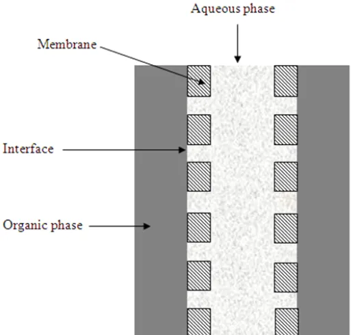
A 2D mass transfer model is developed and solved in this study to determine the concentration distribution of NH3 in a porous membrane considered as the membrane contactor. Fig. 1 shows basic of separation using a membrane contactor.
The feed solution containing dissolved ammonia (NH3) flows with a laminar velocity inside the hollow fibers. Since the diameters of hollow fibers are very low, flow regime is assumed to be laminar in the calculations. The feed solution is flown to the lumen side, while the stripping solution is passed through the shell side. Ammonia is removed from the feed phase by subsequent diffusion through the bulk of liquid and membrane, and becomes absorbed into the solvent.
Fig. 1: Basic principle of separation in membrane contactors
The model is built considering the following assumptions:
´ Steady state and isothermal conditions. ´ Laminar flow in the membrane contactor. ´ Henry’s law is applied for feed-membrane
interface.
´ Non-wetted mode for the membrane is assumed; in which the feed aqueous solution do not fills the membrane pores.
´ There is no reaction zone.
The steady state continuity equation for ammonia transport in the membrane contactor in cylindrical coordinate is obtained using Fick’s law of diffusion. Diffusive flux is estimated from Fick’s law. The continuity equation may be written as [14]:
3 3 3 3 3
3
2 2
2 2
1
NH NH NH NH NH
NH z
C C C C C
D V
t r r r z z
⎡ ⎤
∂ ∂ ∂ ∂ ∂
+ ⎢ + + ⎥=
∂ ⎢⎣ ∂ ∂ ∂ ⎥⎦ ∂ ...(1)
The term Vz is z-velocity in the membrane contactor. To solve Eq. 1, an equation for velocity distribution is required. Velocity distribution in the feed phase is calculated by solving the momentum equation. The most appropr iate momentum equation here is Navier-Stokes equations. Therefore, the momentum and the continuity equations should be coupled and solved simultaneously to calculate the concentration distribution of ammonia in the feed side. The Navier-Stokes equations are defined as follows [14]:
( ( ) ) ( . )
. 0
T
z lumen z lumen z lumen z lumen z lumen
V V V V p F
V
η − − ρ − −
−
−∇ ⋅ ∇ + ∇ + ∇ + ∇ =
∇ = ...(2)
where
η
,V
, and ρ denote fluid dynamic viscosity (kg/m.s), velocity vector (m/s), and density (kg/m3), respectively;p
is pressure (Pa) and
F
is a body force term (N).
Numerical solution of the equations
The main objective of the present study is to simulate a membrane contactor using CFD techniques based on finite element method (FEM). The equations of ammonia transport in the contactor with the boundary conditions were solved using COMSOL Multiphysics. The latter utilizes finite element method for numerical solution of the partial differential equations. The finite element method is combined with adaptive meshing and error control using numer ical solver of UMFPACK. The applicability, robustness and accuracy of this numerical method for the membrane contactors have been proved by some researches [12, 15]. It should be pointed out that the COMSOL creates triangular meshes that are isotropic in size. A large number of elements are then created. A scaling factor was employed for the membrane contactor in the z direction due to a large difference between r and z. Adaptive mesh refinement in COMSOL,
which generates the best and minimal meshes, was applied to mesh the whole geometry of membrane contactor. An IBM-PC-Pentium 4 (CPU speed is 2800 MHz) was used to solve the sets of equations. Parameters used for numerical simulations are taken from literature [10-15].
RESULTS AND DISCUSSION
Concentration distribution of ammonia in the feed side
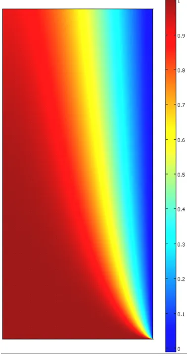
Numerical solution of the continuity equation results in calculation of concentration distribution of ammonia in the feed side of membrane contactor. Fig. 2 shows the concentration
distribution of NH3 in the feed side of the contactor. The feed solution flows from the lumen side at z = 0. The chemical solvent solution flows from the shell side counter-currently. As the feed solution passes in the lumen side, due to the concentration gradient, ammonia is transferred from the bulk of the feed
towards the feed-membrane surface. At the surface of the membrane, only ammonia evaporates into the membrane pores and reaches the shell side. At the shell side of the membrane contactor, an instantaneous chemical reaction occurs between ammonia and acid sulfuric. Fig. 2 also shows that
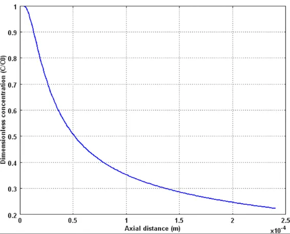
Fig. 4: Axial concentration distribution of ammonia in the lumen side.
concentration gradient is the highest near the membrane, adjacent to the fiber wall.
Radial concentration profile of NH3
Radial concentration distribution of ammonia in the lumen side of the membrane contactor was also investigated in this work. A plot of the radial concentration profile at different axial positions along the lumen side of the membrane contactor is shown in Fig. 3. It is clearly shown that in the region near the axis of the hollow fiber i.e., r = 0 the bulk concentration of ammonia slightly changes. The maximum concentration of ammonia can be observed in the center of the hollow fiber due to axial symmetry assumption. Concentration of ammonia decreases gradually in the region between the center and wall of the fiber side. Eventually, in the region adjacent the membrane-feed interface, concentration sharply decreases. This behavior could be attributed to the formation of the concentration boundary layer near the fiber wall.
Axial concentration profile of NH3
Investigation of concentration profile of ammonia in axial direction would be valuable. In axial direction, the contribution of convective mass transfer flux is dominant. Therefore, axial concentration profile of ammonia along the lumen side of the membrane contactor is shown in Fig. 4. Obviously, at the inlet of membrane contactor, ammonia concentration is the highest. As the feed solution flows in the lumen side, concentration decreases significantly due to interphase mass transfer between feed and solvent (stripping solution). Fig. 4 also reveals that at the region near the contactor entrance, concentration falls sharply. This could be attributed to this fact that in this region, concentration gradient is high and causes significant decrease in the ammonia concentration.
CONCLUSIONS
A mass transfer model was developed to study the transport of ammonia through porous membranes. The model is based on mass transfer between two phases. The model predicts the steady state concentration of ammonia in the membrane contactor. The model was developed considering a hydrophobic membrane which is not wetted by the aqueous feed solution. FEM analysis was applied for numerical solution of the equations. The simulation results revealed that the developed model can predict the formation of concentration boundary layer (CBL).
Nomenclature
C concentration, mol/m3 D diffusion coefficient, m2/s
Ji diffusive flux of species i, mol/m2s L length of the fiber, m
p pressure, Pa
r radial coordinate, m rin inner radius of fibers, m rout outer radius of fibers, m
t time, s
T temperature, K
u average velocity, m/s V velocity in the module, m/s z axial coordinate, m Greek symbols
η
dynamic viscosity (kg/m.s)ρ
density (kg/m3) Abbreviations
FEM finite element method
HFMC hollow-fiber membrane contactor 2D two dimensional
CFD computational fluid dynamics CBL concentration boundary layer
REFERENCES 1. A. Hasanoglu, J. Romero, B. Pérez, A. Plaza,
Ammonia removal from wastewater streams through membrane contactors: Experimental and theoretical analysis of operation parameters and configuration, Chem. Eng. J., 160: 530-537 (2010).
2. T.C. Jorgensen, L.R. Weatherley, Ammonia
removal from wastewater by ion exchange in the presence of organic contaminants, Water Res., 37: 1723-1728 (2003).
Management, 92: 121-130 (2011).
4. M.J. Semmens, D.M. Foster, E.L. Cussler, Ammonia removal from water using microporous hollow fibers, J. Membr. Sci., 51: 127-140 (1990).
5. Z. Milan, E. Sánchez, P. Weiland, C. de Las Pozas, R. Borja, R. Mayari, N. Rovirosa, Ammonia removal from anaerobically treated piggery manure by ion exchange in columns packed with homoionic zeolite, Chem. Eng. J., 66: 65-71 (1997).
6. Saeed Shirazian, Azam Marjani, Farzad Fadaei, Supercritical extraction of organic solutes from aqueous solutions by means of membrane contactors: CFD simulation, Desalination, 277(1-3): Pages 135-140 (2011).
7. Azam Marjani, Saeed Shirazian, Simulation of heavy metal extraction in membrane contactors using computational fluid dynamics, Desalination, 281: Pages 422-428 (2011).
8. A.J. P.F., S.D. A., A review of physical–chemical methods for nitrogen removal from wastewaters, Progress in Water Technology 8: 713-720 (1997).
9. N. Miladinovic, L.R. Weatherley, Intensification of ammonia removal in a combined ion-exchange and nitrification column, Chem. Eng. J., 135: 15-24 (2008).
10. J.-H. Bae, S.-K. Kim, H.-S. Chang, Treatment of landfill leachates: Ammonia removal via nitrification and denitrification and further COD reduction via fenton’s treatment followed by activated sludge, Water Science and Technology, 36: 341-348 (1997). 11. Farzad Fadaei, Saeed Shirazian, Seyed
Nezameddin Ashraûzadeh, Mass transfer modeling of ion transport through nanoporous media, Desalination 281: 325-333 (2011).
12. S. Shirazian, A. Moghadassi, S. Moradi, Numerical simulation of mass transfer in gas-liquid hollow fiber membrane contactors for laminar flow conditions, Simulation Modelling Practice and Theory, 17: 708-718 (2009). 13. A. Bottino, G. Capannelli, A. Comite, R. Di
Felice, R. Firpo, CO2 removal from a gas stream by membrane contactor, Separation and Purification Technology, 59: 85-90 (2008).
14. R.B. Bird, W.E. Stewar t, E.N. Lightfoot, Transport Phenomena, 2nd ed., John Wiley & Sons, New York (1960).