Design and Simulation of Directive High Gain Microstrip Array Antenna for 5G
Cellular Communication
P.Jeyakumar1, Prof.P.Chitra2 and Ms.G.Christina3
1Masters of Engineering, Department of Electronics and Communication Engineering, Coimbatore Institute of Technology, Coimbatore, India. 2Associate Professor, Department of Electronics and Communication Engineering, Coimbatore Institute of Technology, Coimbatore, India. 3Assistant Professor, Department of Electronics and Communication Engineering, Coimbatore Institute of Technology, Coimbatore, India.
Article Received: 27 January 2018 Article Accepted: 23 February 2018 Article Published: 11 April 2018
1. INTRODUCTION
In the recent years the development in communication systems requires the development of low cost, minimal
weight and low profile antennas that are capable of maintaining high performance over a wide spectrum of
frequencies. Microstrip patch antenna is a single layer design which contains mainly these four parts - Patch,
Ground plane, Substrate and Feeding part. It is very simple in construction using conventional microstrip line feed.
Patch can be given any shape but rectangular and circular configurations are mostly used. Ground Plane can be
finite or infinite according to model (Transmission line - model, cavity model, full wave Model or method of
moments) used for analysis of dimensions [1-4]. Relative Permittivity (Єr) and height (h) are two important
characteristics for substrate, Feeding Part can be implemented in these ways - Microstrip line, coaxial probe,
Aperture coupled and Proximity coupled Feed [5-7]. Single microstrip patch antenna has some advantages (low
cost, light weight, conformal &low profile), but it has little disadvantages too like low gain, low efficiency, low
directivity and narrow bandwidth. These disadvantages can be overcome by implementation of many patch
antennas in array configuration. As we increase number of patch elements to form an array, improvement in
performance is observed. For a square patch, the side of the patch is equal. The height h of the dielectric substrate is
usually 0.003 λo ≤ h≤0.05 λo, where λo is the free-space wavelength. The dielectric constant of the substrate (Єr)
is typically in the range 2.2 ≤Єr≤ 12.
2. LITERATURE REVIEW
Due to rapid use of mobile users, challenges occur for service provider to increase the band of spectrum to avoid
shortage of bandwidth and also to provide efficient communication. In this paper directional antenna is used with
the frequency of 2.8 GHz. For the need of less weight, small size, simple design microstrip patch antenna is used.
5Gmobile phones offer effective communication, low latency, and massive connectivity. [8] A B S T R A C T
This abstract demonstrates simple, low cost and high gain microstrip array antenna with suitable feeding technique and suitable dielectric substrate for applications in the range of 26.5 to 40 GHz. The objective of this paper is to design, and fabricate an 8 element square microstrip patch array antenna. Initially antenna as a single patch and after evaluating the outcomes of antenna features; operation frequency, radiation patterns, return loss, efficiency and antenna gain, transformed it to a 1x2 array. Finally, analyzed the 1×4 array, then 1×8 array to increase directivity, gain, and efficiency and better radiation patterns. The simulation has been performed by HFSS software version 13.0 and the desired antenna provides a return loss of -50.99dB at 28 GHz by using Rogers/ RT Duroid dielectric substrate with Єr= 2.2 and height, h= 0.254mm. The gain of the antenna is found to be 21.04 dBi and the side lobe is maintained lower than the main lobe. Since the resonant frequency of these antennas is around 28- 30 GHz, it can be used for K – band applications and 5G Cellular communication systems.
In this paper antenna array is modified with sub array which is placed along the mobile phone to cover wide area.
This technique will avoid traffic rate. Linear phased array antenna with omni directional radiation pattern is used
with this design. Antenna is operated with 18-28 GHz frequency. To cover wide space in 5G mobile phones beam
steering is proposed. Three identical sub arrays are used which is placed by the side of mobile phones where high
gain achieved. Coaxial or probe feed is used to design this antenna. [9]
Wideband antenna of rectangular shaped antenna with microstrip line feed is used for the 5G technology. Operating
frequency of this antenna is at 6GHz. It results gain as 3.7dBwith directivity of 6.62 dB and 500MHz bandwidth.
Antenna parameters are measured to satisfy the needs of 5G technology and also some parameters like atmospheric
absorption of waves due to rain fall or wind which may cause losses of information. Far field radiation pattern is
used for this antenna design. [8]In this paper steerable directional antennas are used in mm wave mobile
communication. Antenna is operated with the frequency of 28 and 38GHz. Antenna design includes two
rectangular patch antennas with single element of RT/ Duroid5880 substrate. Various parameters are measured to
check whether the antenna could able to operate with 5G technology to satisfy the needs of mobile users and also
service provider. Some effective approaches are followed in this design such as, designing an antenna which should
operate with multiple resonances, Optimization of impedance matching; increase the thickness of substrate and
reducing effective permittivity of the substrate. Radiation losses can be reduced by designing thin and high
dielectric constant of the substrate. It provides gain 9.0dB and efficiency as 83%. [10]
Rectangular wideband slotted microstrip patch antenna is designed for 5G technology. It is operated with the
frequency of 5GHz. MIMO technology is implemented to increase the quality of service, gain. Antenna design
includes RT5880substrate with the thickness of 0.6mm and 2.2 as dielectric constant. This antenna design is suited
well for 5G cellular mobile phones which provide reflection coefficient as -36.54dB and bandwidth as 300MHz
[11].
Circularly polarized patch antenna is designed for 5G technology. Miniaturization of patch antenna and beamwidth
enhancement is mainly focus on this paper. 5G mobile phones used for the application of satellite communication,
cellular networks and also used for safety communications. 5G provides accurate global positioning, wide range of
bandwidth, good coverage and high quality of service. To design a suitable antenna for 5G networks certain
parameters are to be considered such as operating frequency, antenna size, polarization, manufacturing cost, ,
bandwidth. Mobile communications requires that the radiation pattern of new antenna design should able to cover
complete azimuth angles and maximum of elevation angles. Directional antennas are preferred which have good
beam tracking ability for satellite communication. Circular shaped folded type antenna with 4and 8 slots are
introduced to reduce the size of an antenna. To enhance the beamwidth of the patch antenna two techniques are
followed. One is dielectric substrate is surrounded by patch antenna and another method is metallic block is added
In this paper antenna is designed with CPW feed which can be suitable for future 5G technology. Operating
frequencies of an antenna are 3.73GHz, 5.56GHz and 8.4GHzwhich is suitable for WLAN, WSN, Wi-Fi/Wi-Max
and Hyper LAN. Microstrip patch antenna is preferred because of its cost, size, weight, flexibility etc. Fractal
technology is used with these designs which provide good impedance matching and it could operate with multiband
of frequencies simultaneously [13]. From the survey paper clear that Steerable directional antenna solution for
future 5G cellular communication systems.
3. PROPOSED SYSTEM DESIGN
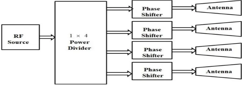
The block diagram of the system is as shown in Figure 1 and the simulation of the system as per design is as shown
in Figure 2. A brief description of system block along with design procedure is as given below
Figure 1 System block diagram
Figure 2 Simulation of System
3.1 Power Divider
Power dividers are used for splitting microwave signals to feed the radiating elements. The microstrip array feeder
network consists of Wilkinson power divider and phase shifters. The four-way power splitter using Wilkinson type
power dividers improves the isolation and matching of the ports. The antenna array is designed using standard
The input impedance of proposed power divider is 50Ω .Therefore the arm impedance is Z0 i.e. 70.71Ω. The
length of the power divider arm is equal to the . Finally the value of the arm resister is 100 Ω.
3.2 Phase Shifter
Phase shifters are components of electronically scanned array that steers the antenna beam in the desired direction
without physically reposition the antenna. Phase shifters are classified as mechanical phase shifters, ferrite phase
shifters, semiconductor device phase shifters and transmission line phase shifters. The transmission line phase
shifter is designed in the present system.
By varying the length of the microstrip line we can obtain the desire phase shift. For that following calculation are
needed.
--- (1)
--- (2)
Where is the phase shift, L is the length of the transmission line, is propagation constant and is the dielectric effective constant. For 22.5 phase shifter length is 25.8813 mm and width is 0.212mm.
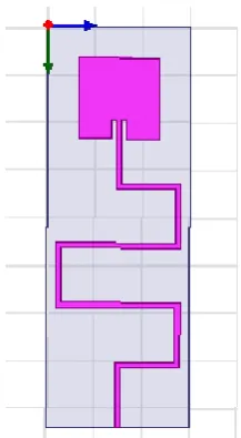
3.3 Design of a Single Element Antenna
The three essential parameters for the design of a Microstrip Patch Antenna are:
Frequency of operation (f
r) = 28 GHz
Dielectric constant of the substrate (Є
r)=2.2
Height of dielectric substrate (h)=0.254 mm
The width of the Microstrip patch antenna is given as:
--- (3)
Therefore, W = 4.2352 mm
The effective dielectric constant is given as:
Therefore, Єreff = 2.035894
The effective length is:
--- (5)
Leff = 3.7545305mm
The length extension is:
--- (6)
ΔL = 0.13229mm
The actual length is given as: L = Leff – 2 ΔL
Therefore, L = 3.4899 mm
Inset fed depth y0 = 0.81777 mm.
Feed width = 0.2123 mm.
After optimization we get,
Figure 3. Design of a Single Element Antenna
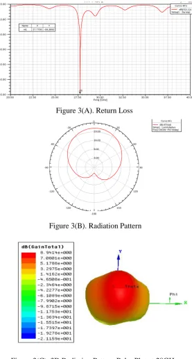
After optimizing and simulation of the antenna the return loss is found to be -59.3692dB at 28GHz and the gain is
found to be 8.50 dBi at that resonant frequency with a bandwidth of about 430 MHz. The RL plot and the radiation
Figure 3(A). Return Loss
Figure 3(B). Radiation Pattern
Figure 3(C). 3D Radiation Pattern Polar Plot at 28GHz
Figure 3(D). Current Distribution Pattern at 28GHz
20.00 22.50 25.00 27.50 30.00 32.50 35.00 37.50 40.00
Freq [GHz] -60.00 -50.00 -40.00 -30.00 -20.00 -10.00 0.00 d B(S (1 ,1 )) HFSSDesign1
XY Plot 1 ANSOFT
m1
Curve Inf o dB(S(1,1)) Setup1 : Sw eep
Name X Y
m1 27.7700 -59.3692
2.00 9.00 16.00 23.00 90 60 30 0 -30 -60 -90 -120 -150 -180 150 120 HFSSDesign1
Radiation Pattern 2 ANSOFT
4. PATCH ARRAY ANALYSIS
a)Design and analysis of a 1×2 array
Figure 4. A 1× 2 Array
Here a 1×2 array is designed with the above said dimensions. Formation of an array requires feeding arrangement
with proper impedance matched network (as shown in fig.2).Inset Fed has been used here, dimensions for feeding
line are: width (w1) of 50 ohm impedance line is 3mm and of 100 ohm (w2) is 2.2 mm. Here an improved gain of
12.43dBi is obtained but consists of side lobes which was not present in the simple single patch. After simulation
we get a return loss of -16.6509dB at 28 GHz.
Figure 4(A). Return Loss
Figure 4(C). 3D Radiation Pattern Plot
Figure 4(D). Current Distribution Pattern at 28GHz
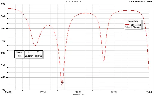
b) Design and Analysis of a 1×4 Array
From the previous array we designed an array with 2 elements and the element spacing of 3.11513mm.
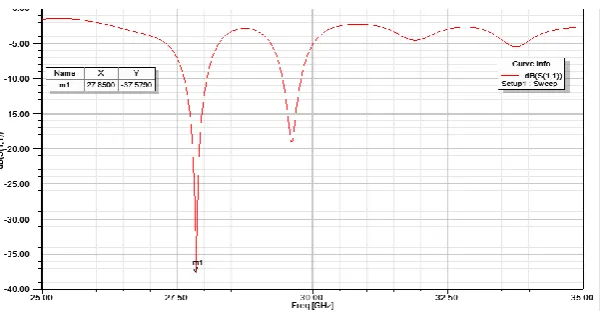
After simulation we get a Return loss of -37.5790dB at 28 GHz with an increased gain of about 16.48dBi and
improved radiation parameters.
Figure 5(A). S-Parameters Plot
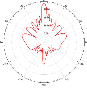
Figure 5(B). Radiation Pattern
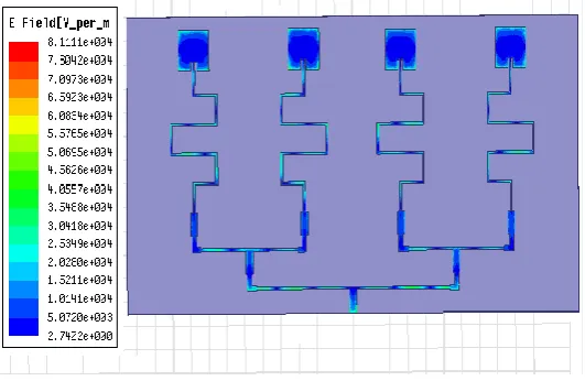
Figure 5(D). Current Distribution Pattern at 28 GHz
c) Design and Analysis of 1 ×8 Array
Now we have designed an array with 8 elements
Figure 6. A 1×8 Array
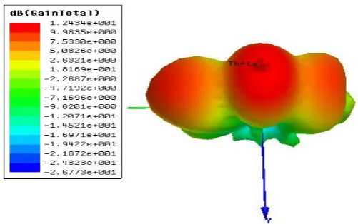
After simulation at 28GHz we get a gain of about 21.04dBi with an increased Directivity of about 20.94dBi with a
Return loss of -50.99dB with a bandwidth of 520 MHz.
Figure 6(B). Radiation Pattern
Figure 6(C). 3D Radiation Pattern
5. COMPARATIVE STUDY OF ALL THE DESIGNS
Elements Return loss
(db) Gain (dbi) Directivity (dbi) Beamwidth (Degree)
Single -59.3692 8.50 8.41 90
Two -16.6509 12.43 12.44 57
Four -37.5790 16.48 16.45 12.54
Eight -50.99 21.04 20.94 4.90
6. CONCLUSION
From above it is clear that with the increase of the no. of elements, there is an improvement of the antenna radiation
parameters like gain, directivity etc. As a future work, we will make comparison between our proposed design for
rectangular patch antenna with different design of triangular patch antennas or other shapes and make the array
with more elements to provide better radiation efficiency and reduction of mutual coupling by using resonator and
reductions in the size. The investigation has been limited mostly to theoretical study due to lack of distributive
computing platform. Detailed experimental studies can be taken up at a later stage to find out a design procedure
for balanced amplifying antennas. These designed antennas are very simple, cost effective and high efficiency for
the applications in GHz frequency ranges. The optimum design parameters (i.e. dielectric material, height of the
substrate, operating frequency) are used to achieve the compact dimensions and high radiation efficiency. The
operating frequency of all our designed antennas is about 28GHz which is suitable for K-band applications.
It would also be possible to design an antenna operating in any other frequency bands by changing the design
parameters. In future, investigate the types of arrays with different feeding techniques which seem to be having
more improved performances for both series feed and corporate feed networks.
REFERENCES
[1] R. Garg, P. Bhartia, I. Bahl and A. Ittipiboon, “Microstrip Antenna Design Handbook”, Artech House, (2000).
[2] K.F. Lee, “Ed Advances in Microstrip and Printed Antennas”, John Wiley, (1997).
[3] D.M. Pozar and D.H. Schaubert, “Microstrip Antennas: The Analysis and Design of Microstrip Antennas and
[4] F.E. Gardiol, “Broadband Patch Antennas”, Artech House.
[5] S.K. Behera, “Novel Tuned Rectangular Patch Antenna as a Load for Phase Power Combining”, Ph.D Thesis,
Jadavpur University, Kolkata.
[6] D.R. Jackson and J.T. Williams, “A comparison of CAD models for radiation from rectangular microstrip
patches”, International Journal of Microwave and Millimeter Wave Computer Aided Design, vol. 1, no. 2, (1991),
pp. 236-248.
[7] D.R. Jackson, S.A. Long, J.T. Williams, V.B. Davis and K.F. Lee, “Computer- aided design of rectangular
microstrip antennas”, chapter 5 of Advances in Microstrip and Printed Antennas, John Wiley, (1997).
[8] Ankita P. Manekar, Dr. S. W. Varade. IJARCCE ISSN (Online) 2278-1021 ISSN (Print) 2319 5940 (2016).
“Design and Simulation of Directional Antenna for Millimeter Wave Mobile Communication”, International
Journal of Advanced Research in Computer and Communication Engineering Vol. 5, Issue
[9] Atima Agarwal, Sweta Agarwal, (2016), “Simulation and Analysis of 5G Mobile Phones
Antenna”,(International Journal of Electronics and Communication Engineering and Technology (IJECET)
Volume 7, Issue 5, pp. 07–12, Article ID: IJECET_07_05_002, ISSN Print: 0976-6464 and ISSN Online:
0976-6472
[10] Chauhan, Brajlata, Sandip Vijay, and S. C. Gupta. “Millimeter-Wave Mobile Communications Microstrip
Antenna for 5G-AFuture Antenna." International Journal of Computer Applications 99.19 (2014): 15-18.
[11] Chong Ming Sam, Mastanesh Mokayef, (2016). “A Wideband Slotted Microstrip Patch Antenna for Future
5G”, EPH International Journal Of Science And Engineering, ISSN: 2454-2016, Vol.2, Issue:7
[12] Mak, Ka Ming, et al. "Circularly polarized patch antenna for future5G mobile phones” IEEE Access 2 (2014):
1521-1529.
[13] Mohan, Gaikwad Pooja, and Mrs SR Chougale. "CPW Feed Microstrip Patch Antenna Design for Future 5G