JETIR1606056 Journal of Emerging Technologies and Innovative Research (JETIR) www.jetir.org 314
Faulty Node detection in Wireless Sensor Network using
Round trip delay and Path
1
NIKHILESH WASNIK
2PROF. KANCHAN DHOTE
1 Student of Electronics and Communication Engineering,
Tulshiramji Gayakwad-Patil College of Engineering andTechnology, Nagpur, India
2 Lecturer of Electronics and Communication Engineering,
Tulshiramji Gayakwad-Patil College of Engineering and Technology, Nagpur, India
Abstract— From few years, wireless sensor networks (WSNs) applications have been increased due to its vast potential to connect the physical world to the virtual world. Similarly an advance in microelectronic fabrication technology reduces the cost of manufacturing portable wireless sensor nodes. It becomes a Fashion to apply the large numbers of portable wireless sensors In WSNs to increase the quality of service (QoS). The QoS of such WSNs is mainly affected by the failure of sensor nodes. Chances of sensor node failure increases with increase in number of sensors. In order to maintain the better QoS under failure conditions, identifying and detaching such faults are essential. In the proposed method, faulty sensor node is detected by measuring the round trip delay (RTD) time of discrete round trip paths (RTP) and comparing them with threshold value.
In this we are experimenting on two sensor nodes and one control unit (Master Node), communication among these nodes is established through Zigbee wireless technology.
Keywords— Faulty Sensor node,Zigbee,RTD and RTP.
I.INTRODUCTION :-
Wireless sensor networks (WSNs) with large numbers of portable sensor nodes has tremendous applications in a variety of fields, like surveillance, home security, military operations, medical, environmental and industrial monitoring. Due to rapid growth in electronic fabrication technology it is possible to manufacture the portable sensor node at low cost with better accuracy and sensitivity. Hence large numbers of portable sensor nodes can be deployed in the field to increase the quality of service (QoS) of such wireless sensor networks. The practices to use large numbers of sensor nodes will increases the probability of sensor node failures in such WSNs. Data analysis based on such faulty sensor node will become incorrect or deviate from the mean value. This wills eventually collaps the quality of service (QoS) of WSNs. The sensor node in the WSNs can become faulty due to various reasons such as battery failure, environmental effects, hardware or software malfunctions. Better quality of service (QoS) is achieved by discarding the data from such faulty sensor nodes in the analysis. This will demand the efficient and accurate detection of faulty sensor nodes in WSNs. The faulty sensor nodes identification suggested is based on comparisons between neighboring nodes and dissemination of the decision. Made at each node. Algorithm proposed in this method can’t detect the malicious nodes. Cluster head failure recovery algorithm used to detect the faulty node has data loss problem, occurring due to transfer of cluster head. Path redundancy technique to detect faulty sensor node is suggested. Redundancy increases the energy consumption and reduces the number of correct responses in network lifetime. Excessive redundant paths in WSNs will slow down the fault detection process. Link failure detection based on monitoring cycles (MCs) and monitoring paths (MPs) is presented. Three-edge connectivity in the network, separate wavelength for each monitoring cycle and monitoring locations are the limitations of this method. The proposed method of fault detection is based on RTD time measurement of RTPs. RTD times of discrete RTPs are compared with threshold time to determine failed or malfunctioning sensor node. Initially this method is tested and verified on three wireless sensor nodes, implemented by using microcontroller and Zigbee.
II.LITERATURE REVIEW :-
(a) Ravindra Navanath Duche and Nisha P. Sarwade, “Sensor Node Failure Detection Based on Round Trip Delay and Paths in WSNs,” in IEEE SENSORS JOURNAL, VOL. 14, NO. 2, FEBRUARY 2014.
This paper Method described to detect the fault is successfully implementedand tested in hardware and software. Due to complexityin hardware implementation, WSNs with large numbers of sensor nodes can’t be realized to verify the suggestedmethod. WSNs with various numbers of sensor nodes like 10, 20, 30, 40, 50 and 100 are implemented and tested in software.
(b) Irfan Al-Anbagi, MelikeErol-Kantarci, and Hussein T. Mouftah, “A Survey on Cross-layer Quality of Service Approaches in WSNs for Delay and Reliability-Aware Applications,”Citation information: DOI10.1109/ COMST. 2014.2363950Communications Surveys & Tutorials.
In this paper, we present a survey on the state of the art of cross-layer QoS approaches in wireless terrestrial sensor networks to achieve delay and reliability bounds in critical applications. Our paper provides a unique
Classification of crosslayer QoS approaches in WSNs which allows surveying a large amount of studies with utmost clarity. Furthermore, we highlight the main challenges of implementing QoS protocols in WSNs and present an overview of QoS-aware WSN applications.
(c) LukmanRosyidi, Hening Pram Pradityo, DediGunawan, RukiHarwahyu, RiriFitri Sari “Dual Hop Multicast Ping Method for Node Failure Detection in ZigBee Loop Network” in International Conference on Information TechnologySystems and Innovation (ICITSI) 2014Bandung-Bali, 24-27 November 2014ISBN: 978-1-4799-6526-7.
JETIR1606056 Journal of Emerging Technologies and Innovative Research (JETIR) www.jetir.org 315
(d) Fu Cai, Cui YongQuan*, Han LanSheng, Fang ZhiCun, “Projection Pursuit based Wormhole Detection in Ad Hoc Network,” in The 2013 IEEE International Conference on High Performance Computing and Communications & 2013 IEEE International Conference on Embedded and Ubiquitous Computing..
In this paper, we propose a wormhole detection mechanism based on Projection Pursuit to detect wormhole. Projection Pursuit is a novel statistical method and its basic idea is to project high-dimensional data on low-dimensional (1-3 dimensional) subspace to find projector that reflects structures and characteristics of data. The feasibility of detecting wormhole by Projection mechanism is based on the Aspects.
(e) Yanbo Zhang, Jiansheng Cao, Xinli Mei “Research on Relationship Between Memory Scale and Lifetime of WSNs with Cluster
Mechanism”2012 2nd International Conference on Computer Science and Network Technology
We use different values of memory scale to test the cluster mechanism deployed in WSNs. Results show that with the increase of memory scale value the lifetime of WSNs has the tendency of more longer existing period. Well, when the memory scale is the integral multiple of 10, such as 10, 20, 30, etc., the lifetime will be the minimal value. This paper gives a quantitative analysis of the relation between length of memory scale and lifetime in WSNs with cluster mechanism.
(f) Ying-Hong Wang, Kuo-Feng Huang, Shaing-Ting Lin “A Grid-based Hole Detection Scheme in WSNs” 2011 International Conference On Network-Based Information Systems.
Wireless Sensor Networks (WSNs) can be widely utilized in many applications, especially in environmental surveillance. However, there exist some holes within the WSNs caused by some factors, such as non-uniform.
Deployment of sensor nodes, some depletion of energy from sensor nodes, the destruction from external forces and the existences of physical obstacles, such as mountains and lakes. These holes will degrade the performance of wireless sensor networks(WSNs). Hence, how to find the position of the holes and utilize the information to improve the performance of WSNs is a significant issue. In order to solve this problem, we proposed detection scheme for grid-based hole in WSNs. By means of grid architecture, we use the grid head to broadcast and forward the request and respond to hole detection. And then, sink will calculate the position of the holes for improving the performance of the WSNs.
(g) R. Morello, C. De Capua, A. Meduri, “Remote Monitoring of Building Structural Integrity by a Smart Wireless Sensor Network” IEEE
2010
The present paper proposes a wireless sensor network in order to verify the building structural health by monitoring the vibration levels transmitted. In particular the network allows to assess if the vibration levels may cause damage to the building or if it needs further study. The vibration levels are compared with fixed thresholds suggested by studies and regulations. The attention has been focused on the reliability of measurement results and, for this purpose, two algorithms have been implemented. The first takes into account the measurement uncertainty of each sensor network node in order to verify the overcoming of fixed threshold through the use of appropriate decision-making rules.
(h) Válter Rocha,, Gil Gonçalves3 “Sensing the World: Challenges on WSNs” 2008 IEEE
The goal of this article is to identify the research challenges onWSNs by dividing them into functional groups, building on previous work. We followed a structured approach based on a simplified yet complete vision of a design space for WSNs. Moreover, this work aims to identify research gaps and investigation fields yet unexplored or hardly explored by researchers in order to plot paths for future research. Several challenges and research areas were identified, like Models for Sensor Networks, Benchmarking Methodologies, Distributed Processing, Interface WSNs and Network Reprogramming.
III.ROUND TRIP DELAY AND PATHS ANALYSIS:-
Round trip delay time of the RTP will change due to faulty sensor node. It will be either infinity or higher than the threshold value. Faulty sensor node is detected by comparing the RTD time of RTPs with threshold value. The threshold value is calculated when the whole network is in proper working, depending upon responces from each node, one fix threshold is selected. The sensor node common to specific RTPs with infinity RTD time is detected as failed. If this time is higher than the threshold value then this senor node is detected as malfunctioning. Detection time of faulty sensor node depends upon the numbers of RTPs and RTD time. Therefore, RTD time measurement and evaluation of RTPs is must to minimize the detection time.
IV. BLOCK DIAGRAM:-
AVR Atmega32 microcontroller Zigbee modules.
Max232.
Temperature Sensor. Humidity Sensor. LCD Display. Power Supply.
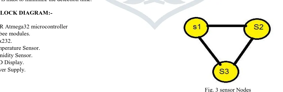
Fig. 3 sensor Nodes
In this we are experimenting on two sensor nodes and one control unit, communication among these nodes is established through Zigbee wireless technology.
Each sensor node consists of micro controller, Zigbee transceiver module and temperature/Humidity sensor and controlling unit consists of Zigbee transceiver, micro controller and buzzer.
JETIR1606056 Journal of Emerging Technologies and Innovative Research (JETIR) www.jetir.org 316
V. INTRODUCTION TO AVR ATMEGA16:-
The AVR core combines a rich instruction set with 32 general purpose working registers. All the 32 registers are directly connected to the Arithmetic Logic Unit (ALU), allowing two independent registers to be accessed in one single instruction executed in one clock cycle.The resulting architecture is more code efficient while achieving throughputs up to ten times faste than conventional CISC microcontrollers.
The ATmega16 provides the following features: 16 Kbytes of In-System Programmable Flash Program memory with Read While-Write capabilities, 512 bytes EEPROM, 1 Kbyte SRAM, 32 general purpose I/O lines, 32 general purpose working registers, a JTAG interface for Boundary scan, On-chip Debugging support and programming, three flexible Timer/Counters with compare modes, Internal and External Interrupts, a serial programmable USART, a byte oriented Two-wire Serial Interface, an 8-channel, 10-bit ADC with optional differential input stage with programmable gain (TQFP package only), a programmable Watchdog Timer with Internal Oscillator, an SPI serial port, and six software selectable power saving modes. The Idle mode stops the CPU while allowing the USART, Two-wire interface, A/D Converter, SRAM, Timer/Counters, SPI port, and interrupt system to continue functioning. The Power-down mode saves the register contents but freezes the Oscillator, disabling all other chip functions until the next External Interrupt or Hardware Reset. In Power-save mode, the Asynchronous Timer continues to run allowing the user to maintain a timer base while the rest of the device is sleeping.
The ADC Noise Reduction mode stops the CPU and all I/O modules except Asynchronous Timer and ADC, to minimize switching noise during ADC conversions. In Standby mode, the crystal/resonator Oscillator is running while the rest of the device is sleeping. This allows very fast start-up combined with low-power consumption. In Extended Standby mode, both the main Oscillator and the Asynchronous Timer continue to run.
The device is manufactured using Atmel’s high density nonvolatile memory technology. The On chip ISP Flash allows the program memory to be reprogrammed in-system through an SPI serial interface, by a conventional nonvolatile memory programmer, or by an On-chip Boot program running on the AVR core. The boot program can use any interface to download the application program in the Application Flash memory.
PIN DIAGRAM:-
VI. INTRODUCTION TO ZIGBEE:-
The Zigbee boards use a V2 XBEE module to interface to the Zigbee network. These modules are compliant with the 2007 Zigbee Pro / ZNET standard. The V2 XBEE modules come in two varieties. One is configured to be the Zigbee network coordinator (EB051C) and the other is configured to be either a router node or an end device node (EB051R). The variety of the module is marked at the top right hand side of the Zigbee board. Coordinator nodes are responsible for creating the Zigbee network and allowing other Zigbee nodes to join. Only one coordinator node can exist on any single network. Router nodes are responsible for routing signals to other routers or to end nodes.
End device nodes are responsible for collecting or depositing real world data to and from the Zigbee network. The Coordinator node and Router nodes are capable of handling up to eight children devices. The children devices can consist of either other Router nodes or End device nodes. If an End device node is configured to sleep then the parent device associated for that node will be responsible for buffering
JETIR1606056 Journal of Emerging Technologies and Innovative Research (JETIR) www.jetir.org 317
any incoming data. Therefore if you are using sleeping End devices you must make sure to poll the parent for data every time the device comes out of sleep mode.The board is compatible with 3.3V and 5V systems.
VII. INTERFACE AND OPERATION:-
The Tarang modules interface to a host device through a logic-level asynchronous serial port. Through its serial port, the module can communicate with any logic and voltage compatible UART or through a level translator to any serial device (For example: RS-232 or USB interface board).
SERIAL INTERFACE:-
Tarang(Zigbee) can be interfaced with a micro controller or a PC using serial port with the help of CTS and RTS are optional. (Refer pin configuration for pin details) Tarang supports serial data with,
Flow Control: Hardware, None Parity: None
Baud Rates: 1200,2400,4800,9600,19200,38400,57600,115200 Data Bits: 8
VIII. LIGHT SENSOR (LDR):-
These Sensors are used in Light detecting equipment for detecting of status of deminised light or high light or no light. The sensor does not get trigger with the noise of alcohol, cooking fumes and cigarette smoke.
They are used in.. Smart city Street light. Safety detection system Node Fail alarm
FEATURES:
Simple analog output Fast response Wide detection range
Stable performance and long life.
IX. COMMUNICATION:-
The XBEE modules are configured by means of using a TTL level RS232 bus to send and receive AT commands. This protocol requires a start bit, eight data bits and a stop bit.The baud rate for the XBEE modules is set to 9600, with no parity and flow control lines RTS and CTS that can be used. AT commands are strings of ASCII data that are sent over the RS232 bus. For more information on the AT commands used by the XBEE module please refer to the V2 XBEE datasheet. Example AT command ATID 234 - Assigns a personal area network identifier of 0x234 or 564 in decimal. 6. V2 XBEE Module. Zigbee is a wireless network protocol specifically designed for low rate sensor and control networks. Compared to other wireless protocols, the Zigbee wireless protocol offers…
low complexity,
reduced resource requirements
And most importantly, a standard set of specifications.
It also offers three frequency bands of operation along with a number of network configurations · And optional security capability.
X. SOFTWARE USED:-
1. Proteus 7.0 for PCB layout and Schematic design
2. Code vision AVR for Mc coding.
3. Digi X-ctu for configuration of Zibgee.
XI .RESULT AND DISCUSSION:-
This paper investigates a novel approach to acquire temperature, Smoke and humidity,light signals using relative low cost and low power components and the Zigbee communication system for the transmission of the acquired data to an central monitoring base station(master). An application for the acquisition and storage of temperature and humidity,light values was created for the central data collection station. The performance of the entire system was tested by laboratory tests using a wsn on order to modify thefault node conditions. Results shown that the presented device correctly follows the protocol which created by Zigbee and the application for the base station properly acquired and stored the data by the apparatus using the Zigbee connection as a transceiver. This approach is useful to monitor which node is get faulty in WSN using round trip delay and path.
XII.REFERENCES
[1] RavindraNavanathDuche and Nisha P. Sarwade , “Sensor Node Failure Detection Based on Round Trip Delay and Paths in WSNs,” in IEEE SENSORS JOURNAL, VOL. 14, NO. 2, FEBRUARY 2014.
[2] Irfan Al-Anbagi, MelikeErol-Kantarci, Hussein T. Mouftah, “A Survey on Cross-layer Quality of Service Approaches in WSNs for Delay and Reliability-Aware Applications,” Citation information: DOI10.1109/ COMST. 2014.2363950 Communications Surveys & Tutorials.
JETIR1606056 Journal of Emerging Technologies and Innovative Research (JETIR) www.jetir.org 318
[4] Fu Cai, Cui YongQuan*, Han LanSheng, Fang ZhiCun, “Projection Pursuit based Wormhole Detection in Ad Hoc Network,” in The 2013 IEEE International Conference on High Performance Computing and Communications & 2013 IEEE International Conference on Embedded and Ubiquitous Computing.
[5] Yanbo Zhang, Jiansheng Cao, Xinli Mei “Research on Relationship Between Memory Scale and Lifetime of WSNs with Cluster Mechanism”2012 2nd International Conference onComputer Science and Network Technology.
[6] Ying-Hong Wang, Kuo-Feng Huang, Shaing-Ting Lin “A Gridbased Hole Detection Scheme in WSNs” 2011 International Conference on Network-Based Information Systems.