R E S E A R C H
Open Access
IP traceback through (authenticated)
deterministic flow marking: an empirical
evaluation
Vahid Aghaei-Foroushani
*and A Nur Zincir-Heywood
Abstract
In this paper, we present a novel approach to IP traceback - deterministic flow marking (DFM). We evaluate this novel approach against two well-known IP traceback schemes. These are the probabilistic packet marking (PPM) and the deterministic packet marking (DPM) techniques. In order to do so, we analyzed these techniques in detail in terms of their performances and feasibilities on five Internet traces. These traces consist of Darpa 1999 traffic traces, CAIDA October 2012 traffic traces, MAWI December 2012 traffic traces, and Dal2010 traffic traces. We have employed 16 performance metrics to evaluate their performances. The empirical results show that the novel DFM technique can reduce the number of marked packets by 91% compared to the DPM, while achieving the same or better
performance in terms of its ability to trace back the attack. Additionally, DFM provides an optional authentication so that a compromised router cannot forge markings of other uncompromised routers. Unlike PPM and DPM that trace the attack up to the ingress interface of the edge router close to the attacker, DFM allows the victim to trace the origin of incorrect or spoofed source addresses up to the attacker node, even if the attack has been originated from a network behind a network address translation (NAT) server. Our results show that DFM can reach up to approximately 99% traceback rate with no false positives.
Keywords: Flow base IP traceback; DDoS attacks; Deterministic flow marking; Authenticated flow marking; Security
1 Introduction
In recent years, much attention has been paid for securing the Internet infrastructure that has become a universal medium for a broad range of communications. Several security approaches have been proposed for securing this infrastructure. The specific security issue, which is the main focus of this study, is anonymous attacks. Due to the trusting nature of the IP protocol, which originally did not include security as a design principle, the source IP address of a packet is not authenticated. Attackers are usu-ally interested in hiding their identity with fake addresses. (Distributed) Denial of Service ((D)DoS) attacks are an example of anonymous attacks where currently there is no obvious way to prevent or trace them. While preventing all attacks on the Internet is far from reality, at least a mech-anism of identifying the source(s) of the attack is needed
*Correspondence: [email protected]
Faculty of Computer Science, Dalhousie University, Halifax, Nova Scotia B3H IW5, Canada
in a situation when prevention fails. This is the reason for designing IP traceback techniques. Traceback is a name given to any method for reliably determining the origin of traffic on the network.
To the best of our knowledge, the state-of-the-art trace-back methods in the literature are able to detect only up to the autonomous system (AS) level or at best, the edge router of the attacker network, because proxies and network address translations (NATs) make it difficult to differentiate activities from distinct hosts. In these cases, to defend against attacks, the victim filters out all traf-fic belonging to the attacker network after identifying the origin of the attack.
Consider a scenario where a computer in a large net-work, such as a university, starts (D)DoS attack by spoof-ing its IP address against a public server (victim). At best, if an IP traceback technique has been utilized in both the university network and the victim side, the victim would be able to identify that the attacker’s network is the university network. When the victim starts filtering
out any traffic from this network, many computers at the university network that have not been involved in the attack will also be filtered out.
In general, there are two ways for routing the network traffic from a local network to the Internet:
1. Valid IP addresses are assigned to the local nodes. The edge router only routes the traffic to and from the Internet. We call these networks as ‘valid networks’. 2. An invalid IP address is assigned to each node in the
local network. In addition to routing, the edge router should do the network address translation. We call these networks as ‘invalid networks’.
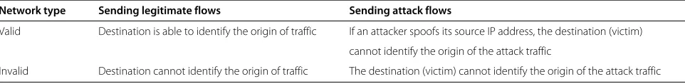
Table 1 shows the differences of these two networks from the perspective of a destination node outside of these networks. As can be seen in this table, only in a situa-tion when a computer does not send spoofed source IP address packets from a valid network that the destina-tion is able to distinguish the exact source of this traffic. In the other three situations, the destination is not able to identify the source node, i.e., the origin of the traffic. Therefore, in the case of attack traffic coming from such networks, the destination (in this case the victim) has to filter out all the traffic flows originating from the attacker’s network.
In this research, we aim to deal with such a problem and propose an IP traceback method to be able to iden-tify the actual attacking machine as accurate as possible in a given network. First of all, we present a brief survey of two promising schemes for tracing cyber-attacks, the well-known probabilistic packet marking (PPM) and the deter-ministic packet marking (DPM) approaches. Then we present a novel approach to IP traceback - deterministic flow marking (DFM). We explore the PPM and DPM in detail and then by investigating the DFM, we analyze the advantages and disadvantages of all three approaches in depth in terms of practicality and feasibility so that the shortcomings of each scheme are highlighted. We employ five different Internet traces (data sets) including Darpa 1999 attack and attack free, Cooperative Association for Internet Data Analysis (CAIDA) Internet traces October 2012, measurement and analysis of WIDE-area Internet (MAWI) December 2012, and Dalhousie 2010 data sets, and use 16 metrics to evaluate the performance of dis-parate traceback schemes. The metrics employed in this work are the following: the computational overhead, the
memory overhead, the bandwidth overhead, the traceback rate, the false-positive rate, mark spoofing by attackers or subverted routers in the attack path, the awareness of the attack path length, the network map and the routing in advance, the number of required packets for traceback, the percentage of marked packets, Internet ser-vice providers (ISP) involvement, the ability to handle fragmentation, the ability to handle major DDoS attacks, and the maximum traceback ability.
The main characteristics of our research that distin-guishes it from other methods include the following:
1. We propose a generalized deterministic flow marking scheme, DFM, which is scalable to large distributed attacks. DFM outperforms PPM and DPM in that it can handle larger-scale DDoS attacks because the maximum number of concurrent attackers in PPM and DPM is limited, whereas there is no such limitation in DFM.
2. Although deterministic IP traceback methods have higher traceback accuracy in comparison to probabilistic marking approaches, this accuracy is achieved by marking all the packets in the network. Deterministic methods need to process every packet and obviously, they incur more processing overhead [1]. In our proposed DFM technique, we aim to minimize this overhead. To achieve this, given that all packets in a flow belong to the same source, we mark every flow, instead of every packet. This leads us to have both advantages of high traceback accuracy of deterministic methods and low processing overhead of probabilistic approaches simultaneously. Our experimental results show that the proposed DFM method has approximately 99% traceback rate with 0% false-positive rate, while it may reduce the number of required packets to be marked for tracing back by 90%.
3. Most of the traceback methods assume that the marking information remains unchanged for as long as the packet traverses the network. Unfortunately, such an assumption is not realistic given the issue of mark spoofing by forged routers. DFM totally eliminates the threat of mark spoofing, not only if spoofed marking is inscribed by the attacker, but also if it is incurred by the compromised routers in the attack path. We show that this can be accomplished by using optional authenticated flow marking.
Table 1 The differences between valid and invalid networks
Network type Sending legitimate flows Sending attack flows
Valid Destination is able to identify the origin of traffic If an attacker spoofs its source IP address, the destination (victim) cannot identify the origin of the attack traffic
4. Finally, unlike DPM that traces the attack up to the ingress interface of the edge router close to the attacker, DFM allows the victim to trace the origin of the incorrect or the spoofed source addresses up to the attacker node, even if the attack has been originated from a network behind a NAT server.
The rest of this paper has the following structure: Section 2 summarizes the related work on IP trace-back and various tracetrace-back schemes are classified from multiple aspects. Then, the actual schemes of PPM, DPM, our proposed DFM, and its optional authen-ticated flow marking feature are presented; and the implications and the challenges associated with each of them are discussed from the perspective of practi-cality and feasibility in Sections 3, 4, and 5, respec-tively. Finally, we provide a comprehensive comparison table for all schemes and present our conclusions in Section 6.
2 Literature review on IP traceback
So far, many traceback approaches have been proposed. According to [1] and [2], we classify existing approaches from multiple viewpoints. Three aspects are selected to classify existing traceback schemes into several categories. They include the basic principle, processing mode, and location.
According to classification by the basic principle, most of the existing traceback methods are categorized into log-ging and marking groups. In loglog-ging methods, the routers keep some specific information of traveling packets [3]. For example, Snoeren et al. [4] have suggested generating a fingerprint of the packet, based upon the invariant por-tions of the packet (source, destination, etc.) and the first 8 bytes of the payload. During the traceback, the routers can verify if a suspicious packet has been forwarded or not. Further improvement in terms of logging only a small portion of each traveling packet at the transient routers have been proposed in [5]. One of the major problems of the logging method is the requirement for high amount of memory and CPU usage on the routers in the attack paths [6]. In marking methods, some or all routers in an attack path send specific information along with traveling packets. The destination may use this information to trace the attacker even if the source IP has been spoofed. This information could be either embedded in the packet’s IP header or sent by generating new packets and consume extra bandwidth [7-10]. In particular, Savage et al. [11] have described a technique for tracing anonymous packet flooding attacks on the Internet towards their source. This traceback can be performed after an attack is identified. While each marked packet represents only a sample of the path it has traversed, by combining a modest number of such packets, a victim can reconstruct the entire attack
path. Dean et al. [12] have presented a scheme for provid-ing traceback data by havprovid-ing routers embeddprovid-ing specific information into packets randomly. This is similar to the technique used by Savage et al. [11], with the major dif-ference being that it is based on algebraic techniques. On the other hand, Song et al. [13] present two new IP marking techniques to solve the IP traceback prob-lem: the advanced marking scheme and the authenticated marking scheme. The authenticated marking scheme sup-ports authentication of routers’ markings. This prevents a compromised router from forging other uncompro-mised routers’ markings. Doeppner et al. [14] identified the source of Denial of Service attacks, provided that a significant percentage of packets are sent from one sub-net. In this method, each router marks its own IP address to the traveling packet with a determinable probability. Moreover, Tseng et al. [15] have proposed a modification to PPM [11] to ensure that the probability of receiving the mark is equal to the original marking probability. Yaar et al. [16] have proposed a method of encoding path iden-tification by marking packets with path fingerprints. They have also another research [17] based on the PPM [11] with further improvements such as 1-bit distance. Victims can identify attack paths after receiving tens of packets encoding. It detects the distance of the attacker by chang-ing the time to live (TTL) field and storchang-ing 1 bit in the IP header. Goodrich et al. [18] have proposed to use relatively large randomized messages to encode router informa-tion. The main idea is to have each router fragment its message into several words and include a large check-sum cord on the entire message randomly in the reusable bits of such a word fragment. Instead of the recovery of the full paths, Belenky et al. [19] and [20], proposed to only record the IP addresses of ingress edge routers. Their scheme, DPM, is simple and easy to implement, and has a little overhead on routers and the victim. This scheme has low processing and memory overhead at the victim machines and edge routers. Additionally, DFM provides an optional authentication so that a compromised router cannot forge markings of other uncompromised routers. Yang et al. [21] take advantage of both marking and log-ging methods and combines both approaches at routers in an attack path. Most marking methods use 16 bits of identification field such as in [11,13,15-17]. However, some other works propose to use 17 bits (identification field and reserved flag) [20,22], 25 bits (identification and type of service (TOS) fields plus reserved flag) [12,18,23], or 32 bits (identification field, flag, and fragment offset) [9,21].
the destination side. In comparison to the probabilistic methods, these methods require more processing over-head but their advantage is providing higher accuracy. An example of probabilistic logging is proposed by Snoeren et al. [4], which was discussed earlier. There are some researches on deterministic marking as well. For exam-ple, the suggested idea by Belenky and Ansari [20] is to store, with random probability of 0.5, the upper or the lower half of the IP address of the ingress interface into the fragment ID field of the packet, and then set a reserve bit indicating which portion of the address is contained in the fragment field. The proposed method by Rayanchu and Barua [22] is similar to Belenky and Ansari [20], but the difference is that they do not embed the IP address in the IP header; instead they only embed the hash of the edge router’s IP address. Most of the recent traceback meth-ods are probabilistic. While the required bandwidth and processing time in these methods are less than the ones required by the deterministic methods, the complexity for reconstruction at the destination side is more. Some well-known examples of probabilistic methods are PPM [11] and many of its variants [15,17], ATA [12], iTrace [7], and others such as in [9,13,14,16-18].
From the perspective of the classification by locations, existing traceback methods are divided into two types: those that send traceback information by the edge routers closest to the source (source group) and in the net-work by some or all routers in the attack path (netnet-work group), respectively. Most of the current traceback meth-ods belong to the network group [11-14]. The purpose of these methods is to identify the attack path entirely or par-tially [9,15-17]. The drawbacks of these methods are the involvement of the routers along the paths and the cost of their processing times and memories for this purpose [4,21,23]. While the goal of source group methods is to identify the attack source, they do not identify the attack path [18,20,22].
Furthermore, the proposed methods in [9,23,24] trace up to the autonomous system (AS) level, while the other aforementioned works trace up to the edge router of the attack source. Song et al. [13] and Goodrich et al. [18] have proposed authentication marking methods, while the other aforementioned works send their marking informa-tion in clear text that are susceptible for mark changing in the case of existing compromised routers in the net-work path. Wang et al. [25] proposed a framenet-work for ‘Sleepy Watermark Traceback (SWT)’ (i.e., watermarking and tracing packets to the attacker’s source IP address, only if the IDS subsystem has determined that there is an attack in progress). This technique is based on traf-fic timing and is quite different from the ones mentioned above in that it injects non-displayable contents into packets. SWT has the following assumptions: (1) Intru-sions are interactive and bidirectional. This paper refers
to intrusions as those attacks aiming to gain unautho-rized access, rather than Denial of Service attacks, so it is not able to trace back Denial of Service attacks that are bidirectional, and attempts to block access to the targeted server by consuming computing resources on the server and by consuming all of the bandwidth of the network connecting the server to the Internet. (2) Routers are trustworthy. (3) There is no link-to-link encryption. So this method is vulnerable to encrypted traffic.
In our previous work, we proposed the DFM approach which allows the victim to trace back the origin of an incorrect or spoofed source IP address up to the attacker node, even if the attack has been originated from a net-work behind a NAT server [26]. DFM is a deterministic approach, which marks every flow (in contrast with mak-ing every packet) and performs on the edge router near the source of traffic. We have shown that using DFM may reduce as many as 90% of marked packets on average required for tracing attacks with no false positives, while it eliminates the spoofed marking embedded by the attacker as well as compromised routers in the attack path in [27].
3 Probabilistic packet marking
In this section, we describe the probabilistic packet mark-ing method called PPM. Based on various IP traceback approaches described in Section 2, PPM falls into the fol-lowing categories: basic principle - marking, processing modes - probabilistic, and location - network group.
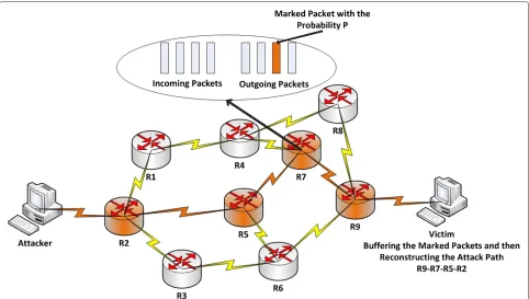
This approach is based on the idea that all routers in the attack path select the packets that pass through them randomly, with a constant probability, and then mark the selected packets by their own IP address (i.e., write a por-tion of their own IP address in the packet IP header). Once the victim gets a large amount of marked packets, it can reconstruct the attack path, even if the IP addresses of the packets have been spoofed. This approach, Figure 1, had been introduced by [28] and later has been improved by [8]. Assume that there aredrouters in an attack path and the marking probability of each of these routers is a con-stant numberp. The optimal value forpis 1/d. However, from the viewpoint of victim, the marking probability of routerRi(1 => i <= d) isp(1−p)d−i that is different thanP[15,29]. It is because subsequent routers may over-ride (re-mark) the packets that have been marked by the previous routers. In other words, the routers that are fur-ther away from the victim are, more likely to be overridden by the subsequence routers. Thus, the closest router to the victim has the highest chance to deliver its marks in the attack path.
3.1 Mark decoding by destination
Figure 1A schematic illustration of PPM approach.All routers in the attack path take part in the traceback.
fields have been embedded in the identification field of packet IP header. Once a router decides to mark a packet (i.e., this decision is independent of other routers), it writes its own IP address to the addr field and zero in dist field. Otherwise, if the router gets a packet that its dist field is zero, it indicates that this packet has been marked by the previous router. In this case, the router would XOR its own IP address with the addr field of the marked packet and would override the result into the addr field again. Finally, if the router does not mark the packet, it always adds one to the dist field.
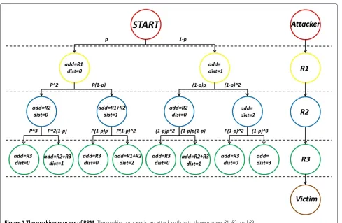
Figure 2 shows the marking process in an attack path with three routersR1,R2, andR3. In theR1 router, there are two cases. The box on the left shows the case that theR1 marks the packets (i.e., it writes its own IP address in addr field and set the dist field to zero), and the box on the right shows the unmarking case by theR1 router (i.e., it just adds one to the dist field). In the R2 router, there are four cases, two boxes on the left show a situation where theR1 router has previously marked the packets. Of these two boxes, the box on the left shows the case that theR2 router marks the packet again (i.e., it writes its own IP address in the addr field and set the dist field to zero), and the box on the right shows the case that the R2 router does not mark the packet (i.e., it XOR its own IP address with the addr field, overrides the result into the addr field, and add one to the dist field). On the other
hand, two boxes on the right show a situation where the R1 router has not previously marked the packets. Of these two boxes, the box on the left shows the case that theR2 router marks the packet (i.e., it writes its own IP address in the addr field and set the dist field to zero), and the box on the right shows the case thatR2 router does not mark the packet (i.e., it just adds one to the dist field). Using the same process for theR3 router, the victim would get eight results. However, some of these eight marking results are similar. For example, boxes number 1, 3, 5, and 7 have the same marking information. By eliminating the duplicate results, four non-repetitive cases remain for the victim.
For the path reconstruction, first of all the victim locates the closest router to itself (i.e.,R3 in Figure 2) by looking for the packet where the dist field is equal to zero. Sec-ondly, becauseR3⊕(R2⊕R3)=R2, the victim can locate theR2 router by looking for the packet where the dist field is equal to 1, and XOR its addr field with the IP address of theR3 router. The victim continues this process until locating the router that is the most far away.
3.2 PPM analysis
Figure 2The marking process of PPM.The marking process in an attack path with three routersR1,R2, andR3.
3.2.1 Computational overhead
For each packet, there is a computational overhead to decide if the packet should be marked or not. In addition, if the packet is marked, there are some more computa-tional overheads such as preparing the marking informa-tion and upgrading the addr and the dist fields. However, in comparison to the computational overhead at the vic-tim side for path reconstruction, the computational over-head of the routers in the attack path is negligible. Authors in [13] show that when there are 25 concurrent attacks to a victim, path reconstruction may take several days with thousands of false positives, while the current DDoS attackers may orchestrate thousands of attack zombies at the same time. In this situation, the victim may never reconstruct the attack path.
3.2.2 Memory overhead
The memory overhead on routers is highly undesirable because it reduces the network performance and requires hardware upgrade. Since the marking process on routers does not store anything, the router’s memory overhead in PPM algorithms is negligible. But on the victim side, a large memory structure for the attack path reconstruc-tion process is required. The victim should store millions
of records in the data structure, and then search on it, to reconstruct the attack path. However, memory overhead on the victim machine is more tolerable than the one on the routers.
3.2.3 False positives
PPM has a high false-positive rate in the face of DDoS attacks. This problem is originated from the basis of the reconstruction algorithm. In this case, the victim should perform two processes; first of all, it should gain the IP addresses of all routers in the attack path and secondly, using the router’s IP addresses, reconstructs the attack path. In PPM, eight packets marked by the same router need to be identified and combined to resume the IP address of that router [9]. Since there is no more sign in the dist field, in a situation when there are several attack paths, it is difficult for the victim to identify which marked packets belong to which router because there are lots of routers in the same distance to the victim. This issue may prevent the attack path reconstruction process.
3.2.4 Mark spoofing by attackers
to the victim. In this situation, the victim may not be able to reconstruct the attack path correctly because the vic-tim cannot differentiate between the fake and the genuine marked packets.
3.2.5 Mark spoofing by subverted routers
There are two kinds of malfunctioning routers that may disrupt the traceback operation by the victim. First of all, the incorrect configured routers that participate in the PPM packet marking may confuse the path reconstruction process. Secondly, the compromised routers can prepare and send fake marked packets that can most likely prevent the victim to trace back to the attack source.
3.2.6 Awareness of the attack path length in advance As described before, the optimal value of marking prob-ability,p, is 1/d. However, once a router decides to mark a packet, it does not have any idea about its path length, d, so it cannot set the pto the optimal value. Authors in [8] suggest to use the constant number 0.04 for p. However, if the victim is under several attacks with differ-ent attack path lengths, using the predetermined constant number forpstrongly reduces the efficiency of the path reconstruction process.
3.2.7 Awareness of the network map and the routing in advance
The PPM algorithm works based on an assumption that the victim should be aware of the network map and the routing in advance to be able to reconstruct the attack path using the IP addresses of the routers among the path extracted from the received marked packets. So the con-cern in this case is how to keep the victim updated about the network map and routing; otherwise, whenever a new router is added to the network, the path reconstruction process will not work correctly.
3.2.8 The number of required packets for traceback In the first implementation of PPM algorithm, the vic-tim requires thousands of packets to reconstruct an attack path [8]. Later, this has been improved to less than 1,000 packets by [13]. However, the number is still high and therefore is a serious drawback of the PPM algorithm.
3.2.9 Fragmentation
PPM uses ID field in the IP header of packets to embed marking information, which is generally used for fragmen-tation. If only a single packet of a fragmented datagram is marked, then the datagram reassembly will fail.
3.2.10 ISP involvement
The path reconstruction process needs to get marked packets from all routers among the attack path. To this end, the marking process should be activated on all
routers in the network. However, what the Internet service providers (ISPs) need to do is limited to updating the router’s IOS and enabling the PPM on the routers. Hav-ing said this, ISPs should do this on all routers, includHav-ing either edge or backbone routers. Indeed, the involvement of all the routers is a major problem of using this method. Given that, in practice it may cross boundaries of ISPs and countries.
3.3 Discussion
So far, several variations of PPM have been proposed [8,15,17]. For example, to counter with ‘awareness of the attack path length in advance’ problem, there are some works [9,23,24] to setdas the number of AS, rather than the number of routers, between the current network and the victim. However, this solution cannot reconstruct the attack path accurately, which is the main goal of the PPM approach.
Song [13] has proposed an advanced and authenti-cated marking scheme for IP traceback. Their approach decreases the high computational overhead and false-positive rate, as the number of the required marked pack-ets for path reconstruction is less than 1,000 in their approach and partially covers the mark spoofing prob-lem. However, their approach cannot resist against the compromised routers in the attack path, since a compro-mised router may be reconfigured to mark the packets incorrectly and still is authenticated by the victim. Unfor-tunately, there is still no approach to cover the problem of malfunctioned routers. Note that the computational overhead and the false-positive rate are in direct propor-tion; as the high computational cost increases, so does the false-positive rate.
One possible solution to counter with the fragmentation problem is to mark the fragmented packets with lower probability. Therefore, the fragmented datagrams have more chance to survive. However, this approach will defi-nitely increase the number of required marked packets for path reconstruction.
As described earlier, as the number of hops between a router in the attack path and the victim increases, the mark information of that specific router is less likely to survive; so from the perspective of the victim, the farther-most router has the lowest chance to deliver its mark in the attack path. One solution to cancel this problem is to use variable marking probability for each router, based on the distance between the current router and the victim [30]. However, the hard part is how to find the number of hops between two ends.
proposed another approach, called DPM [19], to over-come some of the problems of the PPM approach.
4 Deterministic packet marking
DPM is a well-known IP traceback approach and pos-sesses several attractive features such as its ease of imple-mentation and low computational and memory overhead on participating routers as well as the victim machines. Based on various IP traceback approaches described in Section 2, DFM falls into the following categories: basic principle - marking, processing modes - deterministic at packet level, and location - source group.
4.1 DPM scheme
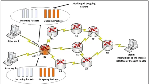
The main goal of DPM, which was first proposed by Belenky and Ansari [19] and later was improved by [20], was to dominate on an obvious issue of PPM. The issue was that each packet in a datagram network is being routed individually so even if the sources and the destina-tions of the packets are the same, they may be routed in different paths. This feature of the packet networks may prevent the attack path reconstruction by victim, using the PPM algorithm. Since each packet may travel a different route from the same source to the same destination, the only address in the network path that is surely the same for all packets is the ingress interface IP address of the closest router to the source of packets. The main idea behind the DPM is that the ingress interface IP address of the clos-est router to the source of the packet is enough to find the attacker network. It should be noted here that in the cur-rent Internet network, the packet routing is mostly stable. However, there is still this potential to route the packets from different paths.
As it is shown in Figure 3, only the ingress interfaces of the edge router marks the packets, and the rest, includ-ing the backbone routers, are exempt. DPM uses 17 bits of the IP header, including 16 bits identification field and 1 bit reserved flag, to embed the marking information to every packet. The 32 bits ingress interface IP address is split into two segments, with 16 bits each: segment 0 - bits 0 through 15 and segment 1 - bits 16 through 31. When a packet passes through an edge router, one segment is selected with equal probability and inserted in the identi-fication field. The victim maintains a table matching the source addresses to the ingress addresses. When the vic-tim gets both segments of an edge router, then it is able to reconstruct the whole ingress interface IP address of that router. One-bit reserved flag plays the rule of a sign for the victim to identify which part of the IP address is carried by the current packet.
DPM has two key features: First of all, DPM only marks the closest ingress edge router to the attacker, and sec-ondly, DPM marks all packets at the ingress interface of the edge routers.
Although the basic DPM approach can handle DoS attacks, it has high false-positive rates under DDoS attacks. The reason behind this is that the victim asso-ciates segments of the ingress address with the source address of the attacker. However, it is a well-known fact that the source IP addresses may be spoofed. Under such attacks, there are at least two cases when the edge router IP address reconstruction may not be effective. Firstly, two or more hosts that have the same source IP address attack the victim and secondly, (D)DoS attackers simply change the source address field for every packet they send. In these cases, the basic DPM is unable to reconstruct any valid ingress addresses [19]. To solve this problem, they improved their basic DPM approach to use a hash function to produce digests or hash values of the ingress address [20]. They proposed that all packets belonging to the ingress interface of an edge router carry the same hash value. Using this hash value, the victim is able to match the correct mark information to form a valid ingress IP address. Therefore, the marking information is formed by three parts: a segment of ingress addressa, the index of segmentd, and digest of ingress addressk. They claimed that the best trade-off for the size of each of these param-eters are a = 4,d = 3, and k = 10, all together 17 bits.
4.2 DPM analysis
To analyze the DPM, we have used the same evaluation metrics that we used to analyze the PPM as discussed in the succeeding sections.
4.2.1 Computational overhead
The CPU overhead of DPM is lower than the PPM approach because unlike PPM, in DPM only the closest edge router to the attacker is responsible for marking (not all routers in the attack path). Moreover, since DPM marks every packet, there is no need for a decision process for marking each packet. However, there are other computa-tional overheads such as preparing marking information and upgrading marking fields. Having said this, in DPM, reconstructing the ingress interface IP address of the edge router is much simpler than the attack path reconstruc-tion process of the PPM approach. Therefore, in the face of DDoS attacks, the victim is able to trace back to the edge router in real time, if DPM is in use. Furthermore, the hash values of the ingress address may be used as a guide to effectively prevent the combinatorial explosion problem of PPM.
4.2.2 Memory overhead
Figure 3A schematic illustration of DPM approach.Only the edge router takes part in traceback.
reconstruction table. It is because in PPM, the victim needs almost 1,000 packets to reconstruct an attack path, while in DPM, only 32/apackets are required to recon-struct the ingress address (i.e., with the suggesteda = 4 [20], DPM requires only eight packets to trace back to the ingress interface address of the edge router close to the attacker).
4.2.3 False positives
As discussed earlier, basic DPM method has a signif-icant limitation to deal with multiple attackers at the same time with the same source IP address. In this sit-uation, the victim cannot recognize which marked frag-ment should be concatenated together to form a valid mark. This causes high false-positive rates. To counter this problem, they propose another method to use a hash function to produce hash values of the ingress interface, called the single-digest DPM technique, or to use a family of hash functions to produce multiple digests of an ingress address, called the multiple-digest DPM technique. In these techniques, hash values are sent along with marked bits to effectively prevent the combinatorial explosion problem. This modification to DPM guarantees the false-positive rate not to go over 1%, if the number of concurrent attackers in a DDoS attack is not more than a limited number. For exam-ple, using 55 datagrams to be marked by the DPM-enabled interface, the maximum number of simultaneous
attackers that can be traced back with the false-positive rate not exceeding 1% in the single-digest DPM tech-nique is 45, and in the multiple-digest DPM techtech-nique is 2,296 [20].
4.2.4 Mark spoofing by attackers
In the DPM approach, each packet is marked when it enters the network. In this case, even if an attacker tries to spoof the mark, the spoofed mark will be overwritten with a correct mark. This automatically obviates the issue of the mark spoofing which PPM has to account for.
4.2.5 Mark spoofing by subverted routers
DPM assumes that a mark remains unchanged for as long as the packet traverses the network. As DPM does not have any mechanism to authenticate the packet mark-ing, this assumption automatically increases the issue of mark spoofing by subverted routers in the attack path. Thus, in an untrusted network such as the Internet and in the case of a compromised router on the attack path, the marking information could be changed and the des-tination would be unable to identify the origin of the traffic.
4.2.7 Awareness of the network map and the routing in advance
As the goal of DPM is not reconstructing the attack path, instead it reconstructs the ingress interface IP address of the edge router, so the awareness of the network map and the routing is not an issue.
4.2.8 The number of required packets for traceback As discussed earlier, 32/apackets are required to recon-struct the ingress address. By the suggesteda = 4 [20], DPM requires eight packets to trace back to the ingress interface address of the edge router close to the attacker, wherearefers to the number of bits in a segment of the ingress address field.
4.2.9 Fragmentation
Like PPM, DPM uses the ID field in the IP header of the packets as well as 1-bit reserved flag to embed the mark-ing information. If only a smark-ingle packet of a fragmented datagram is marked, then the datagram reassembly will fail.
4.2.10 ISP involvement
In DPM, the involvement of the ISPs is very limited. Only the edge routers have to be upgraded to support the func-tion of the deterministic packet marking. Unlike PPM, the other routers in the attack path and the network backbone do not need to be responsible for any function of the DPM traceback process.
4.3 Discussion
In summary, DPM mitigates some of the problems of the PPM. These are the following: its CPU and memory bur-den are far less; it improves the false-positive rate; limits sending the mark spoofed packets by the attackers; does not require for awareness of the attack path length, the network map, and the routing in advance; decreases the number of the required packets for the traceback from almost 1,000 packets to 8 packets; and the involvement of the ISPs is limited only to the edge routers. However, DPM has still some problems such as the following:
• To keep the false-positive rate not exceeding 1%, DPM cannot scale under heavy DDoS attacks as discussed above [20].
• DPM is able to trace back up to the ingress interface of the edge router close to the attacker, not the exact attacker node.
• Although DPM has higher traceback accuracy in comparison to the probabilistic marking approaches, this accuracy is achieved by marking all the packets in the network.
• DPM assumes that the marking information remains
unchanged for as long as the packet traverses the network. Unfortunately, such an assumption is not
realistic given the issue of mark spoofing by forged routers.
The aforementioned four problems were our motivation for proposing the DFM approach [26,27].
5 Deterministic flow marking
In this section, we describe our proposed marking method called DFM. Based on various IP traceback approaches described in Section 2, DFM falls into the following categories: basic principle marking, processing modes -deterministic at flow level, and location - source group. The following are the assumptions of the DFM approach:
• Each node in a local network may change its IP address.
• Media access control (MAC) filtering is enabled in the edge router. However, the attacker may change its MAC address.
• DFM is not an intrusion detection or intrusion prevention system. It is a traceback system, which could work with the aforementioned systems to trace back to the source of the traffic that network
managers or security engineers are interested in.
5.1 Identifiers
DFM uses three identifiers to mark a flow in order to trace up to the attacker node. These three identifiers are as follows:
1. The IP address of the egress interface of the edge router (32 bits): The edge router is the closest router to the attacker node with at least one valid assigned IP address to its egress interface. Some previous researches on IP traceback such as [20] and [31] have proposed to use the ingress interface IP address of the first router in the attack path as an identifier for traceback. However, since DFM should be able to trace up to the attacker node even if the attacker is behind a NAT, the ingress interface IP address will be useless in this case. Since the ingress interface IP address is invalid, the victim is unable to trace the source edge router by an invalid IP address. 2. Network interface identification (NI-ID) (12 bits):
so that a router distinguishes VLAN interfaces by their VLAN IDs. If a network interface is a VLAN interface, a NI-ID is assigned to its VLAN ID instead of the MAC address shared with another VLAN interface. A 12-bit NI-ID, expressed in the range from 0 to 4,095, is sufficient to represent all possible network interfaces and VLANs on an edge router. An edge router keeps an NI-ID table and numbers the interfaces from 0 to 4,095. Each NI-ID table entry consists of an NI-ID and the MAC address of a network interface card. If VLAN interfaces are used, then the entry in the NI-ID table consists of an NI-ID and a VLAN ID. Table 2 shows the NI-ID table of an edge router which uses VLAN interfaces on a physical interface whose MAC address is ‘C’. 3. Node-ID (16 bits): An identifier assigned to each
source MAC address observed from incoming traffic from local networks. Each MAC has a unique Node-ID. Representing Node-ID with 16 bits seems to be sufficient as it makes possible to address all nodes on a LAN connected to each interface of the edge router, even if each LAN is as big as a class B network (the maximum number of nodes in a class B network is216−2). An edge router keeps multiple Node-ID tables, a table for each NI-ID, and numbers the source MAC addresses of the observed incoming traffic from 0 to 65,535. An entry in the Node-ID table is composed of a NI-ID, source MAC addresses of the observed incoming traffic, and a Node-ID. Table 3 shows two examples of a Node-ID table.
Marking each flow by a combination of the IP address of the egress interface (32 bits) + NI-ID (12 bits) + Node-ID (16 bits) = 60 bits identification data distinguishes the traffic of a particular node from the other nodes.
The definition of a flow is accepted as a unidirec-tional sequence of packets between two endpoints that have a flow ID in common with no more than a specific interpacket delay time. Flow ID is the five-tuple infor-mation including the source IP address, the destination IP address, the L4 protocol type (TCP/UDP), the source port number, and the destination port number. While this definition is able to define Transmission Control Proto-col (TCP) and User Datagram ProtoProto-col (UDP) flows, it
Table 2 An example of a NI-ID table
NI-ID MAC address of the connected interface VLAN ID of the edge router to the local network
1 A
2 B
3 C 101
4 C 102
Table 3 Two examples of Node-ID table for NI-ID 1 and 2
NI-ID Node-ID Source MAC addresses of incoming packets
1 1 F
2 E
3 H
4 K
2 1 B
2 S
3 Q
is unable to define Internet Control Message Protocol (ICMP) flows, as ICMP does not use a port number to establish a session. For a good traceback method, it is very important to trace ICMP flows as well because some (D)DoS attacks employ ICMP flooding attack. To this end, we define an ICMP flow as a unidirectional sequence of ICMP packets between two networks that have the six-tuples as source IP address, destination IP address, L4 protocol type (ICMP), ICMP type, ICMP code, and ICMP ID in common with no more than a specific inter-packet delay time. As used in [32], we define 600 ms for interpacket time delay to terminate a flow.
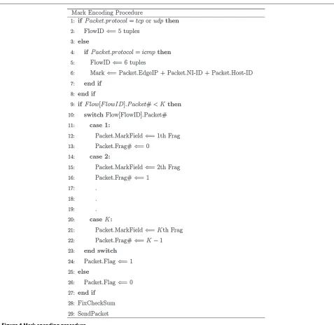
5.2 Mark encoding by the edge router
Figure 4 describes the marking procedure of our proposed traceback method. A 60-bit identification data needs to be passed to the destination for each flow. The identifi-cation data is divided into K fragments. Therefore, the mark containsM = 60/K bits of the identification data andS = log2K bits required to identify a fragment. We also take advantage of one flag bit to identify marked and unmarked packets in a flow. In the experimental results section, we describe how to store the marked bits in some IP header fields that are used rarely.
Figure 5 depicts our choice for partitioning the 60 bits in the firstKpackets of each flow. The firstK packets of every flow carry the mark fragments includingMbits for identification data fragment,Soffset bits to represent 2S possible fragments and one flag bit that should be set to ‘1’ for the marked packets and ‘0’ for the rest.
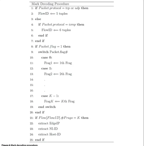
5.3 Mark decoding by destination
Figure 4Mark encoding procedure.
flag, and writes them in the corresponding fields (Table 4). After all fragments corresponding to a flow reach the destination, the source node for the given flow becomes recognizable to the destination. Using DFM, the destina-tion is able to distinguish the traffic of different nodes behind an edge router. As a result, when abnormal traf-fic is observed, the destination can filter the traftraf-fic of each node.
5.4 Discussion
As we discussed earlier, some previous traceback researches use hash functions and send the hash values along with the marked packets to counter the concurrent
Figure 5Partitioning identification data in the firstKpackets of each flow.
Under the same conditions, our proposed method DFM does not need to use hash functions because DFM first detects the flow to construct a valid mark (see Section 5.3). Thus, DFM is safer to counter the problem of multiple attackers with the same IP addresses at the same time.
Furthermore, in our proposed system, it is assumed that the attacker can change its MAC address. To this end, we have four potential scenarios when an attacker changes his MAC address:
1. The attacker spoofs his MAC address with a random MAC address: In this case, we assumed that MAC filtering is enabled in the edge router, the attacker cannot access to the network.
2. The attacker has access to the white list of MAC addresses and he spoofs his MAC address with an active MAC address: The current switches and routers reject concurrent access of more than one node with the same MAC address, so the attacker cannot access the network.
3. The attacker has access to the white list of MAC addresses and he spoofs his MAC with an inactive MAC address: In this situation, after the attack is detected by the victim, it can block the attacker node, using DFM to distinguish the attacker traffic from the rest of traffic, while the other nodes will still have access to the destination (victim).
4. The attacker spoofs his MAC address with several existing MAC addresses in the white list regularly: After detecting the attack using DFM, the victim assumes that several source nodes from the same network belonging to one interface of the edge router try to send malicious traffic. At this point, the victim traces up to level 2 of traceback (edge router
interface) and only cuts off the access of all nodes belonging to this interface, not all nodes that are connected to this edge router. It should be noted here that the other traceback methods in the face of such a situation are only able to trace up to the edge router and therefore, they would cut off the access of all nodes forwarded by the edge router.
As discussed in the first three MAC address chang-ing scenarios, DFM is able to trace three levels up to the attacker node. Only in scenario 4 that the DFM traces two levels up to the source network interface of the edge router. However, this is still much better than the current traceback methods, where they at the best can detect up to the source edge router.
It should be noted here that DFM is able to trace back to the source of the traffic one step behind the ingress inter-face of the edge router. Every router with a valid IP address on its egress interface can potentially act as an edge router. So if a valid IP address is assigned to the egress interface of the closest router to the local network, then DFM would be able to trace back up to the source node. However, if the network administrator defines the farthest connected router to the Internet as the edge router, then probably, there are some subnets behind that edge router. In this case, DFM is able to trace back up to the sub-networks and therefore, fewer number of routers are required to par-ticipate in the DFM marking scheme. This is a trade-off between the accuracy and the number of participant edge routers in the DFM marking scheme.
5.5 Practical comparison of DFM and DPM
Figure 6Mark decoding procedure.
fall into the same categories of classification, but PPM falls in the other categories. In addition, the goal of the PPM is entirely different from DPM and DFM. The purpose of PPM is to identify the attack path, while the goal of DPM and DFM is to identify the attack source. So we cannot compare the performance of the PPM directly with the DPM and DFM under the same conditions on the same network. Thus, we only compared the performance of DFM and DPM under the same conditions and on the same network platform [27].
Figure 7 is a schematic illustration of both DPM and DFM approaches, and is a comparison between two meth-ods. To evaluate DFM and compare the result with DPM, we have employed both approaches on five discrete net-work traces including Darpa 1999 attack and attack-free traces [33], CAIDA anonymized Internet traces October 2012 [34], MAWI traffic archive December 2012 [35], and Dal2010 data sets:
Table 4 An example of the reconstruction table withK =2,M=30andS=1
Flow ID First Second Identification
fragment fragment
AC100C14055A5585B02A005006
Srcip = 172.16.112.20 Edge router IP = 172.16.0.1
SrcPort = 1370 AC100001 4004005F NI-ID = 1
Dstip = 85.133.176.42 Host-ID = 23
DstPort = 80 Protocol = tcp
AC10715410925585B817001511
Srcip = 172.16.113.84 Edge router IP = 172.16.0.1
SrcPort = 4242 AC100001 40080037 NI-ID = 2
Dstip = 85.133.184.23 Host-ID = 13
DstPort = 21 Protocol = udp
first and third weeks do not contain any attacks. The second week contains a selected subset of attacks from the 1998 evaluation in addition to several new attacks. There are 201 instances of about 56 types of attacks distributed throughout forth and fifth weeks data.
2. CAIDA network traces contain anonymized passive traffic traces from CAIDA’s Equinix-Sanjose monitor on high-speed Internet backbone links [34]. The CAIDA data set we employed in this work is a standard tcpdump file from October 2012. 3. MAWI network traces are from a traffic data
repository maintained by the MAWI Working Group of the WIDE Project [35]. These traffic traces are in tcpdump format, and the IP addresses in the traces are scrambled because of privacy reasons.
4. Dal2010 network traces were captured in 2010 on the Dalhousie network. Traces were captured from the main Internet link. Given the privacy-related issues, data is filtered to scramble the IP addresses and each packet is further truncated to the end of the IP header so that all payloads are excluded.
Moreover, the checksums are set to zero since they could conceivably leak information from short packets. However, any information regarding size of the packet is left intact.
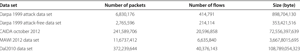
Table 5 represents statistical information of all of afore-mentioned network traffic traces.
We implemented a testbed network in our research lab (Figure 8). As shown in this figure, one local network for evaluating our DFM technique on all of the five data sets is given above. For this purpose, we replayed these data sets on our testbed network using tcpreplay and tcprewrite
open source applications [36]. In addition, we imple-mented two real-time programs using Winpcap library by C++ [37], one for marking and the other for tracing back the source of the flows for DFM. The marking program runs at the source edge router and only marks those flows traveling from the inside of the network to the outside. At the same time, the traceback program runs at the des-tination nodes and tries to trace the source nodes of the marked traffic.
5.5.1 Traceback and marking rates
As described before, our marking method divides a 60-bit identification data for each flow toK fragments and passes it to the destination by the firstKpackets of each flow. Therefore, the mark inserted in each packet contains M= 60/Kbits of the identification data,S= log2Kbits to identify a fragment and 1 bit flag to identify the marked and the unmarked packets in a flow. However, finding the best number ofK is an important issue. There are three metrics that are important in choosing the best value for K:
• TR, traceable rate: the ratio of the number of successfully traced back packets to all packets • MR, marking rate: the ratio of the marked packets by
the edge router to all packets
• NB, number of bits: the total number of bits that are embedded to the IP header of each mark-carrying packet
Figure 7A schematic of both DPM and DFM approaches.Comparison of marking and the traceback procedures of both DPM and DFM approaches. Blue lines: DPM; green lines: DFM.
betweenK,M,S, NB, TR, and MR for all four data sets on DFM approach. For the better understanding of the topic, Figure 9 presents five charts, each chart for one data set showing the values of TR, MR, and normalized NB from 0 to 100% for several values ofKfor the proposed DFM approach.
The most interesting thing that can be observed in Figure 9 is that unlike the existing traceback methods where reducing MR causes reducing TR, in DFM reducing
MR increases TR. It means that DFM can achieve a high TR with marking a lower number of packets, i.e., low MR. The reason is that clearly the flows with lower number ofKpackets are unable to carry allK-marked fragments. In this case, decreasingKalso decreases MR. As a result, this increases the number of flows that can carry all K fragments and it increases the traceback rate, TR.
However, while decreasing K causes higher TR and lower MR, which are both desirable; it also increases NB,
Table 5 Statistical information of Darpa 1999, CAIDA October 2012, MAWI December 2012 and Dal2010 data sets
Data set Number of packets Number of flows Size (byte)
Darpa 1999 attack data set 6,830,176 414,791 898,704,130
Darpa 1999 attack-free data set 2,765,596 214,114 353,421,516
CAIDA october 2012 241,589,706 20,596,858 72,556,397,639
MAWI 2012 data set 11,6737,412 6,635,840 3,667,8015,695
Figure 8The testbed network to analyze DFM.
which is undesirable. Since TR is a very important factor in DFM, we focus on the values ofK ≤ 5 that reason-able traceback rates (around 90% and more). On the other hand, K = 1 cannot be an option because in that case the required NB becomes 61 bits. It should be noted here that finding 61 rarely usable bits in an IP header to embed marking bits is almost impossible. SelectingKvalues from 2 to 5 is a trade-off between MR and NB. While lowerK values have better MR and worse NB, higherKvalues have worse MR and better NB. As most traceback methods uti-lize 16 bits of identification field in the IP header to embed the marking bits [11,13,15-17],K= 5 seems to be a good option. It requires 16 bits of IP header and around 12% to 33% of all packets end up being marked. However, in our implementation it is possible to setK= 2. In this case, we have better MR compared toK = 5 (around 8% to 15%), but more NB (32 bits). Based on the previous works on IP traceback [9,21], it is possible to use the identification, the flag and the fragment offset fields of IP header as a 32-bit marking field (Figure 10). Fortunately, the use of the frag-ment and the identification fields in the IP header affects only the 0.06% of the legitimate packets [9,21].
It should be noted here that each flow requires at leastK packets to carry all the marking fragmentations. So if the number of packets in a flow is less thanK, then this flow cannot be traced back by DFM. This is the reason why changing theKchanges the TR in Table 6.
Our results show that marking the first two packets of every outgoing flow using DFM makes it possible to cor-rectly determine the origin of 93% to 99% of packets (TR), while it only requires 9% to 15% of all packets to be marked (MR). Moreover, DFM correctly determines the origin of 90% to 99% of packets (TR) by marking 12% to 33% of all packets (MR) if the first five packets of every outgoing flow are marked (italic entries in Table 6).
Table 7 shows the evaluation of the DPM approach on all of our five evaluation data sets, using the same TR and MR metrics as we used to evaluate the DFM approach. Although it is expected to have 100% trace-back rate using DPM approach, actually as it is shown in Table 7, TR for the DPM approach is less than 100% because fragmented traffic will be corrupted by the DPM and there is some fragmented traffic in our evaluation data sets. If a single fragment of the original datagram
Table 6 The relationship betweenK,M,S, NB, TR, and MR on all evaluation data sets for the DFM approach
Darpa 1999 Darpa 1999 CISDA MAWI Dal2010
attack attack-free Oct 2012 Dec 2012
K M S NB TR MR TR MR TR MR TR MR TR MR
(M+S+1)
1 60 0 61 100 7.74 100 6.07 100 8.52 100 5.68 100 10.85
2 30 1 32 98.65 14.13 99.94 12.09 92.91 9.96 97.23 8.60 93.33 15.02
3 20 2 23 98.62 20.51 99.94 18.11 91.76 10.82 96.96 11.38 92.53 18.79
4 15 2 18 98.61 26.89 99.88 24.11 91.03 11.43 96.84 14.12 91.46 22.21
5 12 3 16 98.24 33.18 99.45 30.00 90.56 11.93 96.20 16.70 89.77 25.21
6 10 3 14 78.64 35.54 81.73 32.35 90.11 12.34 92.88 18.62 87.11 27.67
10 6 4 11 66.98 39.66 70.97 36.77 88.82 13.40 86.06 23.17 76.98 33.36
12 5 4 10 64.55 40.63 68.65 37.98 88.48 13.78 84.27 24.75 74.63 35.07
15 4 4 9 60.83 41.26 64.99 38.98 88.08 14.28 81.74 26.55 72.13 37.07
20 3 5 9 59.71 41.69 63.38 39.94 87.64 14.98 77.84 28.37 68.35 39.40
30 2 5 8 59.27 42.28 62.21 41.32 87.12 16.15 74.73 30.66 64.82 42.35
60 1 6 8 58.49 43.43 58.90 43.51 85.95 18.91 70.76 34.14 59.50 46.98
Figure 9TR, MR, and normalized NB for different values ofKfor the DFM approach.(a)Darpa attack data set.(b)Darpa attack-free data set. (c)CISDA data set.(d)MAWI data set.(e)Dal2010 data set.
is marked, the reassembly function would fail at the destination.
By comparing Tables 6 and 7, it can be seen that DPM has higher traceback rate compared to DFM (TR); how-ever, this accuracy is achieved by marking all the packets in the network (MR).
5.5.2 Memory usage
The following are the memory usage comparison between the DFM and the DPM approaches:
• Memory usage of DFM approach in the edge router. The space required for running DFM on an edge router is equal to the sum of the required space of three tables namely the flow table, the NI-ID table, and the Node-ID table [26]. In our practical (on our testbed) analysis, the total required space for running the DFM method was less than 26 KB. Below we explain the details of each of these tables and the space required by them:
Figure 10Using the gray fields as marking field in IP header for
K=2.
– NI-ID table. For every interface on the edge router and for every VLAN (in case of existence of VLANs on the edge router), 9 bytes including 12 bits for NI-ID, 48 bits for MAC address, and 12 bits for VLAN ID are stored. Since the implemented evaluation network has assigned one interface for evaluating the DFM approach (Figure 8), this table only requires 9 bytes in the edge router. – Node-ID table. For every record in the NI-ID table, DFM stores a separate Node-ID table. For every new observed source MAC address, a 60-bit record including 12 bits NI-ID and 48 bits MAC address should be stored. Thus, the size of this table varies and is based on the number of unique source MAC addresses that are observed. The DFM approach utilizes a memory management algorithm, so when it does not observe a source MAC address for a specific period of time, it removes its record from the Node-ID table. In our experimental results, the maximum required space for storing the Node-ID table was 945 bytes. – Flow table. In addition to NI-ID and Node-ID
tables, DFM utilizes another table called the
Table 7 TR and MR of DPM approach for all five evaluation data sets
Data Darpa 1999 Darpa 1999 CISDA MAWI Dal2010 set attack attack-free Oct 2012 Dec 2012
TR 99.83 99.98 99.26 99.42 99.33
flow table. Each row in this table belongs to an observed flow. DFM stores 180 bits for each flow including the following three items:
∗ Flow ID, 13 bytes. For TCP and UDP flows, the flow ID is the sum of five-tuples including 4 bytes source IP addresses, 2 bytes source port numbers, 4 bytes destination IP addresses, 2 bytes destination port numbers, and 1 byte of protocol, which makes 13 bytes in total. For ICMP flows, the flow ID is the sum of six-tuples including 4 bytes source IP addresses, 4 bytes destination IP addresses, 1 byte protocol, 1 byte ICMP type, 1 byte ICMP code, and 2 bytes ICMP ID, altogether 13 bytes. ∗ Flow mark, 60 bits as described
earlier.
∗ Packet number, 2 bytes. The edge router increases this number by one in the corresponding flow record for every transmitted packet. In other words, this number indicates the number of packets in a flow. DFM uses this number for keeping track of K first packets of every flow.
DFM no longer needs keeping a record of a flow when the flow is over. End of a flow is detected by an interpacket delay that is more than 600 ms. Therefore, the space required for flow table varies and is based on the number of concurrent flows. Table 8 shows the size of the flow table in the DFM approach for each of the five evaluation data sets. Since the maximum number of concurrent flows was 1131, the maximum required space to store the flow table was about 25 KB on our testbed.
• Memory usage of DFM approach at the victim side. The victim maintains a reconstruction table,
matching the flow ID andK possible mark fragments. For every observed flow, a 13 bytes flow ID and 60 bits identification data should be stored. Like the flow table in the edge router, the victim no longer needs keeping the record of a flow when a flow is over. Therefore, the space required for the reconstruction table varies and is based on the number of concurrent flows.Table 8 shows the size of the reconstruction table in DFM approach for each of the five evaluation data sets. Since the maximum number of concurrent flows was 1,131, the maximum required space to store the reconstruction table was about 23 KB.
• Memory usage of DPM approach in the edge router. Since marking process on the edge router by the DPM approach only stores the hash value of the ingress IP address, router’s memory overhead in DPM algorithms is negligible.
• Memory usage of DPM approach at the victim side. The reconstruction table consists off parts, and each of those parts is a 217-bit structure (2dareas,k segments in every area, and2abits in every segment) [20].f Refers to the number of hash value functions. We implemented the DPM approach with the suggested four hash value functions [20]. Therefore, the required space for reconstruction table was 64 Kb.
5.6 Authenticated flow marking
Using DFM, the destination is able to trace up to the source node of the received traffic by extracting the edge router’s IP Address, NI-ID, and Node-ID from the marked packets of each flow. Although DFM has promising results, in case of a compromised router on a network path, the marking bits could be changed and the destination would be unable to identify the origin of the traffic.
To this end, we propose to add an optional digital sign-ing mechanism to DFM. A straightforward approach for the digital signing is to use the RSA algorithm. How-ever, RSA has two major disadvantages. Firstly, it is very expensive to compute. Secondly, the memory overhead is large (128 bytes for a 1,024-bit RSA signature). Thus, we choose to use the Elliptic Curve Digital Signature Algorithm (ECDSA) [38]. Elliptic curve systems offer more security per bit increase in the key size compared to RSA or Diffie-Hellman public key systems. A 160-bit elliptical curve key is equivalent to a 1,024-bit RSA key in terms of security. Security is not the only attractive feature of elliptic curve cryptography. Elliptic curve cryptosys-tems also are more computationally efficient than the RSA and Diffie-Hellman systems [39].
Table 8 The size of the flow table in the DFM approach for each of the five evaluation data sets
Data set Darpa 1999 Darpa 1999 CISDA MAWI Dal2010
attack attack-free Oct 2012 Dec 2012
Number of concurrent flows 843 241 1,131 930 1,021
Flow table size at the edge router (byte) 18.5 5.5 25 20.5 22.5
Reconstruction table size at the destination (byte) 17 5 23 19 20.5
The required space for each flow in the flow table is 180 bits and in the reconstruction table is 164 bits (13 bytes flow ID and 60 bits identification data).
To this end, the edge router creates 42 bytes signature value (size of ECDSA digital signature with 160 bits ellip-tical curve key) by applying ECDSA signing algorithm to 60 bits identification data plus 13 bytes flow ID. This 42 bytes signature should also transfer to the destination along with 60 bits of identification data. Obviously, it is not a good idea to embed 42 bytes of data to the IP header because embedding 42 bytes data and 60 bits identifi-cation data to 32 bits marking field requires at least 13 packets, while looking at Table 6 shows thatK = 13 has a bad TR (64% to 88%). So we decided to add 42 bytes ECDSA digital signature to the end of the Kth packet payload of each flow. It is assumed that when this system is used it would be known that DFM is using ECDSA signing algorithm.
5.7 Signature verification by destination
As described earlier, each destination maintains a recon-struction table (Table 4). In the case of authenticated flow marking, each destination should add two more fields to this table: one field for ECDSA digital signature data and another field for the signature verification status (Table 9). We assume that the destination already has the public key of each edge router that is participated in the authen-ticated flow marking method, e.g., by downloading the
public key from the CA. When the destination gets the signed flow, it uses the sender’s public key to authenticate the sender. If the two agree, the destination knows that the author of the mark was in possession of the edge router’s private key and that the mark is in fact valid; otherwise, it would reject the flow.
One advantage of the proposed authenticated flow marking method is that it is optional for the destination to extract and validate the signature for every flow while it does not get attacking flows. In a situation when the vic-tim is under attack, it may use the signature to validate the mark to find the attacker node. Therefore, the destina-tion is not forced to always consume its CPU and memory resources to verify ECDSA signature.
5.8 Experimental results of authenticated DFM evaluation
To evaluate our proposed authentication DFM method, we applied this method on the same five data sets as used above. To this end, we modified our original DFM imple-mentation in both the attacker and the victim sides to include the authentication component. In this case, the program at the source (attacker) side has optional ECDSA digital signature embedding with 160-bit elliptical curve key as well as the flow marking component. Whereas the program at the destination side has optional edge router
Table 9 An example of the reconstruction table for the DFM authenticated flow marking method
Flow ID First mark frag Second mark frag Digital sign Identification Sign verification
AC100C14055A5585 B02A005006
Srcip = 172.16.112.20 EdgeRouter IP =
SrcPort = 1370 AC100001 4004005F 42 bytes 172.16.0.1 Verified
Dstip = 85.133.176.42 sign data NI-ID = 1
DstPort = 80 Host-ID = 23
Protocol = tcp AC10715410925585 B817001511
Srcip = 172.16.113.84 EdgeRouter IP =
SrcPort = 4242 AC100001 40080037 42 bytes 172.16.0.1 Failed
Dstip = 85.133.184.23 sign data NI-ID = 2
DstPort = 21 Host-ID = 13