11
A New Scheme to Direct Torque
Control of Matrix Converter-Fed
Five-Phase Permanent Magnet
Synchronous Motor
Arjang Yousefi-Talouki and S. Asghar Gholamian*
Babol University of Technology,
Faculty of Electrical and Computer Engineering, Babol, Iran
*
Corresponding email: [email protected]
Abstract
Multiphase machines have gained an increasing attention due to their more advantages in comparison with three-phase machines. In recent literatures, only voltage source inverters (VSIs) have been used to supply five-phase drives. Matrix converters (MCs) pose many advantages over conventional VSIs, such as lack of dc-bulk capacitors, high quality power output waveform and higher number of output voltages. Due to some special applications of multiphase machines such as ship propulsion and aerospace, the volume of these drives is an important challenging problem. As a consequence, using MCs can be a reasonable alternative. In this paper, a new direct torque control (DTC) algorithm using a three-to-five phase MC is proposed for five-phase permanent magnet synchronous motors (PMSMs). All of output voltage space vectors of three-to-five phase MC are extracted and a new switching table is proposed. Because of higher number of output voltages in MCs, there is a degree of freedom to control input power factor to keep close to unit moreover the torque and flux control. In other words, this proposed method use the advantages of both DTC method and MCs. Simulation results show the effectivenessof presented method in different operation modes.
12
1. INTRODUCTION
Multiphase machines have gained an increasing attention due to their several advantages over three-phase systems, such as reducing the amplitude of torque pulsations, lowering the dc link current harmonics, reducing the stator current per phase without increasing the voltage per phase and increasing the reliability [1,2,3,4,5].
Direct Torque Control (DTC) is one of the active researched control schemes which is based on the decoupled control of flux and toque. This method was first proposed for phase induction machines and then was implemented on three-phase permanent magnet synchronous motors (PMSMs) [6,7]. DTC provides a very quick and precise torque response and also has very simple instruction, i.e., no need of rotary coordinate transformation, inner current regulator, or pulse width modulation (PWM) block. The basic principle of DTC is to directly select stator voltage vectors according to the differences between the reference and actual torque and stator flux linkage. Also, this method was presented for the first time in five and six-phase induction motors in [8,9]. L. Parsa, et al. investigated the DTC algorithm for a five-phase PMSM in [10].
Matrix converter (MC) is an interesting power converter that was developed in the last two decades [11,12,13]. These kinds of converters have many advantages such as including an adjustable input power factor, bidirectional power flow, high-quality power output waveforms and the lack of bulky capacitors. Due to their higher number produced output voltage space vectors, one can do more precise control. DTC method using MCs was first proposed for induction motors in [14]. In that literature, in addition to torque and flux control, input power factor has been controlled to be close to unit. In the next years, DTC scheme using MC has been implemented on PMSMs [15]. Despite of more advantages of MCs in comparison with conventional voltage source inverters (VSIs), in the literatures related to the multiphase motor drives, only VSIs have been used to feed these motors.
Five-phase voltage source inverters produce 32 output voltage vectors. Noting that three-phase VSIs produce 8 voltage vectors, it seems that due to higher number of output voltage vectors in five-phase VSIs, more precise control in electromagnetic torque and stator flux can be achieved. But it has been shown in [10] that, because of large stator currents harmonic problems, it is better to use just 10 voltage vectors. This issue will be explained in detail in this paper.
13
presented method. All of output voltage vectors of a three-to-five phase MC are obtained and the effects of these vectors on torque and flux variations are investigated and also a proper switching table is proposed. Simulation results show that using this presented switching pattern table, besides the control of input power factor, good and precise control in electromagnetic torque and flux is achieved.
2. MATHEMATICAL EQUATIONS OF FIVE-PHASE PMSM
The stator voltage equation of the motor is as follow
d dl T R
Vs = s s+ (1)
s
R , Is and Λsare the stator resistance, currents and flux linkages matrices respectively.
The equation of air gap flux linkage can be presented as follow
m s s m ss
s =Λ +Λ =LI +Λ
Λ (2)
ss
L is the stator inductance matrix and Λmis the flux linkage of the rotor permanent magnet.
One can write the stator voltage, flux and torque equations of a five-phase
sinusoidally wounded motor in synchronous rotating reference frame
(d − −q z1−z2−z3) using the following transformation matrix.
− + − + − + − + + + − − + + − − = 2 1 2 1 2 1 2 1 2 1 ) 5 4 sin( ) 5 2 sin( ) 5 2 sin( ) 5 4 sin( ) sin( ) 5 4 cos( ) 5 2 cos( ) 5 2 cos( ) 5 4 cos( ) cos( ) 5 2 sin( ) 5 4 sin( ) 5 4 sin( ) 5 2 cos( ) sin( ) 5 2 cos( ) 5 4 cos( ) 5 4 cos( ) 5 2 cos( ) cos( 5 2 ) ( π θ π θ π θ π θ θ π θ π θ π θ π θ θ π θ π θ π θ π θ θ π θ π θ π θ π θ θ θ T (3)
In above equation,
θ
is the rotor electrical angle. The stator flux linkages are given by14
Stator voltage equations in transformed reference frame are obtained as
dt d i r V dt d i r V dt d i r V dt d i r V dt d i r V s Z s Z s s Z s Z s Z s s Z s Z s Z s s Z ds qs ds s ds qs ds qs s qs 3 3 3 2 2 2 1 1 1 λ λ λ λ ωλ λ ωλ + = + = + = + + = + + = (5)
Where,
ω
is the rotor electrical speed.All the 10n±1th (n=0,1,2…) winding space harmonics and voltage time harmonics with abcde phase sequence are related toq−d subspace, while all the 10n±3th (n=0,1,2…) winding space harmonics and voltage time harmonics with acebd phase sequence are related to Z1−Z2subspace. For a sinusoidally wounded
motor, magnitude of third space harmonic within stator winding function is very low, which leads to tiny magnetizing inductance in Z1−Z2 model and the only
impedance to Z1−Z2voltage is stator resistance plus stator leakage inductance as can
be seen in (5). Thus, Even a low order voltage harmonic in Z1−Z2plane, cause to
large distortion in stator current.
Electromagnetic torque equation in dqreference frame can be written as follow
[
m qs d q dsqs]
e i L L i i
p
T ( )
2 5
2 + −
= λ (6)
3. DIRECT TORQUE OF FIVE-PHASE PERMANENT MAGNET
SYNCHRONOUS MOTOR
15
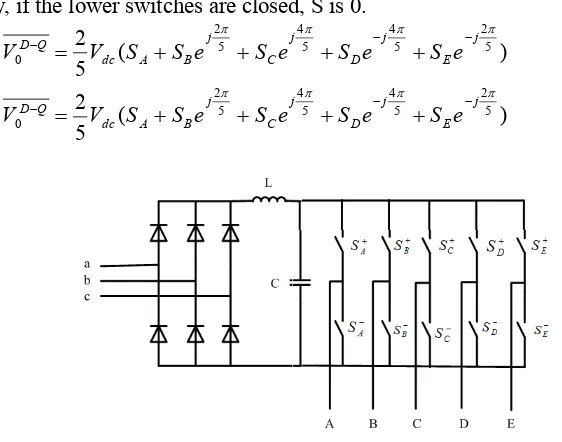
obtained. If the upper switches of converter are closed, S is considered to be 1 and on contrary, if the lower switches are closed, S is 0.
) ( 5 2 ) ( 5 2 5 2 5 4 5 4 5 2 0 5 2 5 4 5 4 5 2 0 π π π π π π π π j E j D j C j B A dc Q D j E j D j C j B A dc Q D e S e S e S e S S V V e S e S e S e S S V V − − − − − − + + + + = + + + + = (7)
Figure 1: Five-phase voltage source inverter
16 10110 10000 00110 10100 10111 11100 10101 00100 10001 00101 11101 00111 01101 00001 01100
01001 01111 11001
01011 01000 00011 01010 11011 01110 11010 00010 11000 10011 11110 10010
D-Q plane Z1-Z2 plane
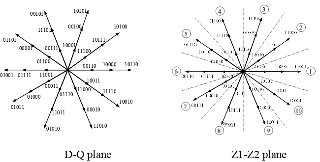
Figure 3: Thirty two voltage vectors of a five-phase VSI in D-Q and Z1-Z2
subspaces
The principle of selecting a voltage space vector in the conventional DTC of five-phase drive is similar as that in DTC of three-phase drives. It is shown in [7] that, for three-phase PMSM with uniform air gap, electromagnetic torque is
δ φ
φ ( )sin
1 2 3 max t L p
Te r s
= (8)
Where,
ϕ
s( )t presents the amplitude of stator flux,ϕ
rmaxis explanatory of rotor flux permanent magnet, pis the number of poles andδ
is angle between stator flux and rotor flux.For a five-phase motor equation (8) can be rewritten as
δ φ
φ ( )sin
1 2 5 t L p
Te rD−Q sD−Q
= (9)
17
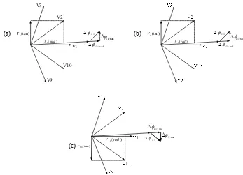
flux and electromagnetic torque are need to be increased, voltage vectors V2 and
3
V should be chosen. As it is illustrated in Figure.4, the tangential component of
voltage V3is bigger than tangential component ofV2. Therefore, voltage space vector
3
V is more effective on increasing electromagnetic torque. On the other hand, the
radial component of voltage vector V2 is bigger than voltageV3. Thus, V2 is more effective on increasing stator flux. Due to the control of electromagnetic torque is more demanding than stator flux, thus, voltage vector V3 will be selected. As the same, if stator flux needs to be increased and electromagnetic torque needs to be decreased, voltage space vectorV9should be chosen. On the other hand, to decrease
stator flux magnitude and increase electromagnetic torque, voltageV4is chosen.
Finally, voltage vectorV8 decreases both stator flux magnitude and electromagnetic torque.
Figure 4: Effects of voltage vectors on electromagnetic torque and stator flux
magnitude. (a) Effectsof voltage vector V2, (b) Effects of voltage vector V3, (c) Effects of voltage vector V10
V1 V2 V3
V9 V10
1
s rad
φ −
∆
`
1 tan
s
φ−
∆
1
s φ ∆
2( )
V rad
2(tan) V
1
s rad
φ −
∆
1 tan
s
φ−
∆
1
s φ ∆
2( )
V rad
2(tan) V
1
s rad
φ −
∆
1 tan
s
φ−
∆
1
s φ ∆ 10( )
V rad
1 0(t a n ) V
(a) (b)
18
As can be seen in Figure 3, voltage space vectorsV12 andV22have the same
direction that of V2. Having the same direction, these vectors have the same effects
on changing electromagnetic torque and stator flux magnitude but VoltageV2 has
faster response due to its bigger magnitude than V12 and alsoV22.
As aforementioned in previous section and can be seen from equation (9), only the components of D−Qsubspace, produce output torque and components of
1 2
Z −Z subspace produce harmonics in stator currents. It should be noted that, the outer decagon of the D−Qsubspace is mapped into the inner decagon of the
1 2
Z −Z subspace and vice-versa. The medium decagon of D −Qis mapped into the
medium decagon ofZ1−Z2.If the large voltage space vectors ofD−Qsubspace are
energized, the small voltage vectors ofZ1−Z2subspace will be energized
simultaneously. Therefore, less harmonic currents will be obtained. If the medium vectors ofD−Qsubspace are selected to be applied to motor, then medium vectors ofZ1−Z2subspace will be selected at the same time. Thus, because of applying
larger vectors ofZ1−Z2subspace in comparison with previous status, harmonic
currents will be increased in this time. The same conception is true for selecting small vectors ofD−Qsubspace and large vectors ofZ1−Z2subspace, i.e., in this
condition, the higher harmonic currents will be achieved in comparison with the last two status of selecting switching voltage vector. Thus, according to this analysis, it is preferable to choose only large voltage space vectors ofD−Q subspace.
According to aforementioned analysis, a switching table has been proposed in [10] which is shown in table.1. It should be noted that,dϕ = −1(dϕ =1), show that the stator flux linkage has to be decreased (increased). On the other hand,dTe = −1(dTe =1) is the explanatory of this fact that the electromagnetic torque has to be decreased (increased).
19
Electromagnetic torque and stator flux are obtained using stator voltages and currents in stationary reference frame. Stator flux angle also can be achieved using equation (12). ) ( 2 2 5 ds qs qs ds
e i i
p
T = λ −λ (10)
∫
∫
− = − = dt I R V dt I R V s s a ) ( ) ( αβ β β α α λ λ (11) α β β α λ λ λ λ λ λ 1 2 2 ( − = < + = tg s s (12)Where, α is the direct axis and βis the perpendicular axis.
Table 1: Voltage vector switching table
dϕ dTe SECTOR
1 SECTOR 2 SECTOR 3 SECTOR 4 SECTOR 5 SECTOR 6 SECTOR 7 SECTOR 8 SECTOR 9 SECTOR 10
1 1 V3 V4 V5 V6 V7 V8 V9 V10 V1 V2
1 -1 V9 V10 V1 V2 V3 V4 V5 V6 V7 V8
-1 1 V4 V5 V6 V7 V8 V9 V10 V1 V2 V3
-1 -1 V8 V9 V10 V1 V2 V3 V4 V5 V6 V7
αβ
Vα
Vβ i
α
iβ θ
20
4. DIRECT TORQUE CONTROL USING MATRIX CONVERTER
4.1 Three-phase to Five-phase Matrix Converter
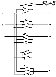
The power circuit topology of a three-phase to five-phase matrix converter is illustrated in Figure.6. As can be seen, there are five legs which each leg have three bidirectional switches in series.
Switching constraint isSka+Skb +Skc =1. Where, k ={ ,A B C D E, , , }is the
output phase of the converter and j ={ , , }a b c is the input phase of the converter.S , is
the status of switches which 1 denotes that the switch is closed and 0 implies that the switch is open.
Figure 6: Schematic diagram of a three-phase to five-phase matrix converter
The state of converter can be represented using following transformation matrix.
= ) ( ) ( ) ( ) ( ) ( ) ( ) ( ) ( ) ( ) ( ) ( ) ( ) ( ) ( ) ( t S t S t S t S t S t S t S t S t S t S t S t S t S t S t S T Ec Eb Ea Dc Db Da Cc Cb Ca Bc Bb Ba Ac Ab Aa (13)
Using transformation matrix, we will obtain
[
Vo(t)] [ ][
= T Vi(t)]
(14)
[
Ti(t)]
=[ ]
TT[
Io(t)]
21
Where,VoandIoare output voltage and output current vectors, respectively. Also,Viand Iiare input voltage and input current vectors.
A three-phase to five-phase MC produce 5
3 =243output voltage space vectors. Among these vectors, 93 vectors have fixed direction and called stationary vectors group. As aforementioned for conventional five-phase VSIs, for a five-phase matrix converter, 30 output voltage space vectors are large vectors, 30 vectors are medium and the last 30 vectors are small vectors (Figure.7). It should be noted that three vectors are zero voltage space vectors. These 93 vectors consist of configuration which connects 4 of the output phases to one of the input phases and the fifth phase of output side is connected to another input phase (medium vectors). The other configuration of stationary vectors group connects 3 of the output phases to one of the input phases and the 2 other output phases to another input phase (Large and small vectors). If all of output phases are connected to a same input phase, zero voltage vectors will be produced. As it has been mentioned in previous sections, using medium and small vectors inD −Q plane, leads to large harmonics in stator current. Thus, in this paper authors only will use large voltage vectors ofD −Q subspace.
The space vector of output voltages can be expressed as follow
) (
5
2 25 45 45 25
0
π π
π π
j E j D j C j B
A V e V e V e V e
V
V = + + + − + − (16)
Where, V V V VA, B, E, Dand VEare output line-to-neutral voltage vectors of five phase
, , ,
A B C D andE, respectively.
In the same way, the space vector of input currents can be expressed as follow
) (
3
2 23π −23π
+ +
= a b j c j
i i ie ie
I (17)
Where, i ia, band icare input line currents.
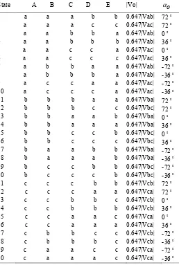
The switching states of a 3 5× MC are shown in table 2. It should be noted that, only the large vectors of MC are shown in this table. The medium and small voltage space vectors are shown in tables A and B,in appendix which are not used in this paper.
22
1 V 2 V 3
V 4
V
5
V
6
V
7
V
8
V V9
10 V
2 V
Figure 7: Output line-to-neutral voltage vector configurations (large vectors)
23
Table 2: Switching states for 3-phase to 5-phase matrix converter (large vectors)
State A B C D E |Vo| αo
1 a a a b b 0.647|Vab| 72o
2 a a a c c 0.647|Vac| 72o
3 a a b b a 0.647|Vab| 0o
4 a a b b b 0.647|Vab| 36o
5 a a c c a 0.647|Vac| 0o
6 a a c c c 0.647|Vac| 36o
7 a b b a a 0.647|Vab| -72o
8 a b b b a 0.647|Vab| -36o
9 a c c a a 0.647|Vac| -72o
10 a c c c a 0.647|Vac| -36o
11 b b b a a 0.647|Vba| 72o
12 b b b c c 0.647|Vbc| 72o
13 b b a a b 0.647|Vba| 0o
14 b b a a a 0.647|Vba| 36o
15 b b c c b 0.647|Vbc| 0o
16 b b c c c 0.647|Vbc| 36o
17 b a a b b 0.647|Vba| -72o
18 b a a a b 0.647|Vba| -36o
19 b c c b b 0.647|Vbc| -72o
20 b c c c b 0.647|Vbc| -36o
21 c c c b b 0.647|Vcb| 72o
22 c c c a a 0.647|Vca| 72o
23 c c b b c 0.647|Vcb| 0o
24 c c b b b 0.647|Vcb| 36o
25 c c a a c 0.647|Vca| 0o
26 c c a a a 0.647|Vca| 36o
27 c b b c c 0.647|Vcb| -72o
28 c b b b c 0.647|Vcb| -36o
29 c a a c c 0.647|Vca| -72o
30 c a a a c 0.647|Vca| -36o
4.2 Proposed DTC using Three-phase to Five-phase Matrix Converter
24
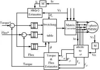
corresponding input line current, is chosen as third variable. By controlling this variable, unity input power factor will be achieved.
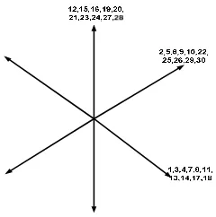
The active output voltage vectors of a 3 5× matrix converter are shown in Figure.7 which V1−V10show the MC vectors as the same direction as those vectors
delivered by VSI. The magnitude of output voltages is related to input line-to-line voltages. It can be seen in Figure.9 that the input voltage is divided to six sectors starting at−π/ 6rad .
As an example, we can assume that V1is the VSI output voltage vector in a conventional DTC. From Figure 7 and table 2, it appears that voltage vectors (3, 5, 13, 15, 23 and 25) must be chosen. As it is illustrated in Figure.9, in each sector there are six voltage vectors. The two small vectors cannot be used for DTC method because of their change of sign in the middle of sector. If the input line-to-neutral lies in sector 1, the switching configurations which can be utilized are 3 and 5. The reason of not choosing the four other vector is that, vectors 15 and 23, are related to the small line to line voltage vectors in sector 1 (VbcorVcb) and cannot be used.
Vectors 13 and 25 are in the opposite direction of V1 and therefore cannot be used.
Vector 3 and 5 impose two input current vectors with different directions, as shown in Figure 8. Thus, this degree of freedom can be used for controlling the input power factor. If the average value of sin( )ψ needs to be decreased, voltage vector 5 should be chosen. On the contrary, if the average value of sin( )ψ has to be increased, voltage vector 3 has to be applied.
Based on aforementioned principle, a switching table is proposed which is shown in table.3. The first column is related to the output voltage vectors selected by the conventional DTC. The other 6 columns contain the sectors which the input line-to-neutral voltage vectors lie in. If the average value of sin( )ψ needs to be increased
the right sub-column is chosen. On the contrary, if the average value of sin( )ψ needs to be decreased the left sub-column is chosen.
25 2
π
−
6
π
−
2
π
6 π
5 6 π
5 6
π
−
2
π
−
Figure 9: Six sectors of input voltage vectors
αβ
Vα Vβ i
α
iβ
θ
sin( )ψ
T
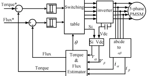
V i θ
Figure 10: Schematic diagram of proposed DTC using matrix converter
Table 3: Switching Table
Sec 1 Sec 2 Sec 3 Sec 4 Sec 5 Sec 6
+1 -1 +1 -1 +1 -1 +1 -1 +1 -1 +1 -1
V1 5 3 15 5 13 15 25 13 23 25 3 23
V2 6 4 16 6 14 16 26 14 24 26 4 24
V3 2 1 12 2 11 12 22 11 21 22 1 21
V4 29 17 27 29 7 27 9 7 19 9 17 19
V5 30 18 28 30 8 28 10 8 20 10 18 20
V6 25 13 23 25 3 23 5 3 15 5 13 15
V7 26 14 24 26 4 24 6 4 16 6 14 16
V8 22 11 21 22 1 21 2 1 12 2 11 12
V9 9 7 19 9 17 19 29 17 27 29 7 27
26
5. SIMULATION RESULTS AND DISCUSSION
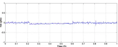
Simulation has been done using Matlab/Simulink to verify the effectiveness of proposed method. The parameters of motor are given in table.4. Simulation has been done in different situations without and with speed loops. Figure. 11 shows a case of open speed loop simulation that actual torque follows the command torque very well (Figure.11 (b)). Figure.11 (c) shows the electromagnetic torque waveform of classical DTC. As can be compared between figure 11(b) and 11(c), in the proposed DTC, electromagnetic torque follows its reference target as well as classical DTC. The average value of displacement angle of sinϕis shown in Figure.12. It can be observed that sin
ϕ
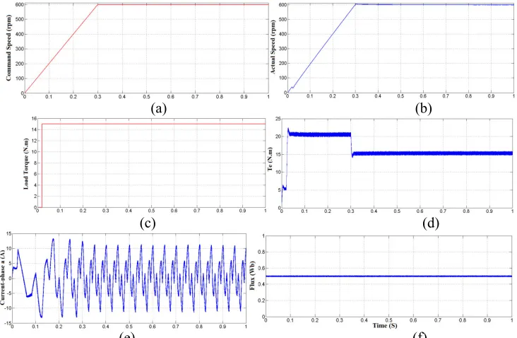
is controlled such a way that to be closed to zero. Therefore unity input power factor is achieved. Triangular speed command is implemented to proposed drive in no load situation which is illustrated in Figure.13. As can be seen in this figure, motor speed tracks its reference very well. Figure.14 and Figure.15 show the characteristics of electromagnetic torque, stator flux and stator current for classic DTC and proposed DTC respectively and both in rotor speed of 600 rpm. As it is shown in these figure, in proposed method electromagnetic torque and stator flux follow their references as well as that of classical method. Electromagnetic torque reference is produced using PI controller in speed loop and stator flux reference is set to be equal to rotor permanent magnet flux magnitude which is 0.5 Wb. As it was described in previous sections, stator current is distorted because of large magnitude of third harmonic currents. This distortion would be more if small and medium vectors of output voltage space vectors are implemented to motor. Filtered input line current and its corresponding line-to-neutral voltage are shown in Figure.16. As it can be shown, input voltage and input current are in phase as it is expected and therefore unity input power factor is achieved.27
Table 4: Five-phase permanent magnet synchronous motor parameters
P Ld Lq Rs J B ψf
4 18mh 42mH 0.7 Ω 0.025 0.005 0.5 (Wb)
(a) (b)
(c)
Figure 11: From top to bottom: (a) command torque, (b) actual torque for proposed
DTC, (c) actual torque for classical DTC
28
(a) (b)
(c)
Figure 13: (a) command speed, (b) actual speed, (c) electromagnetic torque under no
load condition
(a) (b)
(c) (d)
(e) (f)
Figure14: Simulation of classical DTC, (a) command speed, (b) actual speed, (c)
29
(a) (b)
(c) (d)
(e) (f)
Figure 15: Simulation of proposed DTC, (a) command speed, (b) actual speed, (c)
load torque, (d) electromagnetic torque, (e) stator current (phase-a), (f) stator flux
30
(a) (b)
(c) (d)
(e) (f)
(g)
Figure 17: Simulation of proposed DTC, (a) actual speed, (b) load torque, (c)
electromagnetic torque, (d) filtered input line current and its corresponding voltage (phase-a), (e) filtered input line current from Sec. 0.4 to 0.55, (f) filtered input line current from Sec. 0.55 to 0.85, (g) filtered input line current from Sec. 0.85 to 1
6. CONCLUSION
31
REFERENCES
[1] L. Parsa, H.A. Toliyat. Fault-tolerant interior-permanent-magnet machines for hybrid electric vehicle applications. IEEE Trans. Vehicular Technol. 56 (4) (2007) 1546–1552.
[2] E. Levi, R. Bojoi, F. Profumo, H.A. Toliyat. S. Williamson, Multiphase induction motor drives—a technology status review. IEE Elec. Power Appl. 1 (4) (2007) 489–516.
[3] P.T. Norton, P.E. Thompson. The naval electric ship of today and
tomorrow.in: Proc. 3rd All Electric Ship Symp., Paris, France, 2000, pp. 80– 86.
[4] L. Parsa, H.A. Toliyat. Five-phase permanent magnet motor drives for ship propulsion applications.in: Proc. IEEE Electric Ship Technologies Symposium, Philadelphia, US, 2005, pp. 371–378.
[5] D. Vizireanu, S. Brisset, X. Kestelyn, P. Borchet, Y. Milet, D. Laloy. Investigation on multi-star structures for large power direct-drive wind generator.Electr. Power Compon. Syst. 35 (2) (2007) 135–152.
[6] L. Takahashi and T. Noguchi. A new quick response and high efficiency strategy of induction motor.in Conf. Rec. IEEE IAS Annu. Meeting,1985, pp. 495–502.
[7] L.Zhong, M.F. Rahman, K.W. Lim. Analysis of Direct Torque Control in Permanent Magnet Synchronous Motor Drives. IEEE Trans. Power Elec. Vol. 12, No. 3, May. 1997, pp. 528-536.
[8] Toliyat HA, Xu H. A novel direct torque control (DTC) method for five-phase induction machines. In: Fifteenth annual IEEE applied power electronics conference and exposition (APEC), vol. 2; 2000.
[9] Bojoi R, farina F, Griva G, Profumo F, Tenconi A. Direct torque control for
dual three-phase induction motor drives. IEEE Trans IndAppl
2005;41(6):627–1636.
32
[11] P. Wheeler, J. Rodriguez, J. Clare, L.Empringham, and A. Weinstein. Matrix converters: A technology review. IEEE Trans. Ind. Electron., vol. 49, no. 2, pp. 276–288, Apr. 2002.
[12] P. Wheeler, J. Clare, M. Apap, and K. J. Bradley. Harmonic loss due to operation of induction machines from matrix converters. IEEE Trans. Ind. Electron., vol. 55, no. 2, pp. 809–816, Feb. 2008.
[13] Djahbar, B. Mazari. Performances Evaluation of Two-Motor Drive with Matrix Converter Supply and Series Connection of Stator Windings. IREE 2010; V0l: 5(4); pp. 1504-1511.
[14] D. Casadei, G. Serra, and A. Tani. The use of matrix converters in direct torque control of induction machines. IEEE Trans. Ind. Electron., vol. 48, no. 6, pp. 1057–1064, Dec. 2001.