http://www.sciencepublishinggroup.com/j/ijmea doi: 10.11648/j.ijmea.20170505.17
ISSN: 2330-023X (Print); ISSN: 2330-0248 (Online)
Feature Estimation and Registration of Point Clouds in
Reverse Engineering
Hongguang Zhu, Xu Zhang
College of Mechanical Engineering, Shanghai University of Engineering Science, Shanghai, China
Email address:
[email protected] (Hongguang Zhu), [email protected] (Xu Zhang)
To cite this article:
Hongguang Zhu, Xu Zhang. Feature Estimation and Registration of Point Clouds in Reverse Engineering. International Journal of Mechanical Engineering and Applications. Vol. 5, No. 5, 2017, pp. 282-286. doi: 10.11648/j.ijmea.20170505.17
Received: March 24, 2017; Accepted: April 8, 2017; Published: October 30, 2017
Abstract:
Cultural relic is the carrier of information, such as production, life, science and technology, art and so on. However, due to natural and man-made reasons, artifacts are often destroyed. Excavation site is the most common variety of cultural relics, the need for cultural relics repair. Because the artifacts are generally made on the rotating disk, so the object of this study is the rotating debris. The geometric characteristics of the rotating body are the rotation axis, the contour line, the radius of rotation and the angle of fit. Estimate the overall characteristics of the rotary body have important reference value for computer aided restoration of cultural relics. The efficiency and precision of the axis of rotation, contour is estimated by different methods are different, which will directly affect the follow-up work of this paper focuses on the stitching, from the axis of rotation estimation, contour calculation, rotation radius and central angle calculation is discussed.Keywords:
Cultural Relic Restoration, Revolving Body, Rotation Axis, Contour, Radius of Gyration1. Introduction
Antiquities is an important research object of archaeologists, through the study of ancient artifacts can have a further understanding of ancient culture. But because of the natural and human destruction, the excavation site is often a piece of cultural relic, need further work before stitching it possible to recreate the original. Because most of the cultural relics are made on the turntable, the object of this paper is to study the splicing of the fragments of the rotating body. The vibration environment test of electronic equipment to the sine test and random vibration test test. The general approach is to find out the structure resonance frequency or direct definition of the vibration frequency, the frequency of anti resonance tests.
[3]
Structures in the resonant state of local displacement will produce, caused by the local bending deformation, resulting in fatigue damage. It can quickly assess the structure strength, structural defects, and evaluation In this paper, the dynamic characteristics of the specimen are tested, and the dynamic characteristics of the low voltage circuit breaker are studied.
In this paper, the rotation of the body fragments of the splicing process is as follows:
(1) preprocessing: 3D point cloud feature information obtained by 3D scanner;
(2) classification: according to the characteristics of the 3D point cloud of the obtained fragments, the fragments from the same cultural relics are classified into one class;
(3) splicing: on the basis of classification, local matching and global matching;
(4) repair: geometric and texture information complete the lost.
2. Calculation of Rotating Shaft
The rotating shaft is an important geometric feature of the rotating body. Yacoub [1] and Sablatnig [2] proposed the axis of rotation estimation based on Hough transform fragments, specific divided into 3 steps: (1) plane fitting method based on vector estimation; (2) Hough transform; (3) by using principal component analysis method to estimate the shaft. This method is robust to noisy data, but slower. The optimization method proposed by Halir [3] is more accurate than the previous one, but it is not good enough to use the least square method. Zhang Zongxia [4] of Shandong University uses the method of two surface fitting to calculate the normal vector, and uses the method of linear geometry to calculate the rotation axis of [5]. In this paper, the author calculates the normal vector by three methods (1 with average method adjacent triangles as vector vectors; 2 plane vector method based on fitting calculation; 3 two quadric surface fitting method based on vector calculation), and draw the following conclusions: in the absence of noise under the condition of normal vector obtained by various methods are approximately equal, when adding noise, calculated by two quadric surface fitting method of vector method is lower than the other two has strong anti-interference ability, but the speed is slow. Based on the calculation method of the vector author estimate the rotation axis, the experiments show that: the method of vector triangle method to calculate the axis of rotation is simple and fast, plane fitting method to get the speed of a rotating shaft was obtained by two quadric surface fitting method of vector rotation speed is slow, but the accuracy is high.
Based on the calculation of the linear geometric axis of rotation by the rotating axis and normal all vertices of the intersection, so the rotation axis and normal in PLUCKER coordinates of 6 tuple, may be the axis of rotation is X = (X,
x
), L = (l, li), I = 1, 2... k, k is the total number of vertices.Object function:
F(x) = k i i2 i 1
x l x l T
X MX
=
⋅ + + =
∑
( ) . (1)Constraint condition :
2
x =X DXT =1
Among:
M= , i
[
l4 i l5 i l6 i l1 i l2 i l3 i]
T
A A A = ( ) ( ) ( ) ( ) ( ) ( ), D = diag (1, 1, 1, 0, 0, 0).
The objective function based on the constraints of the minimum solution is PLUCKER axis coordinate X = (x,
x
). According to the point line coordinates P = (X×X) /X2, direction vector x, spatial rotation axis linear equation expression.Figure 2 is the result of using the linear geometry method to obtain the rotation axis:
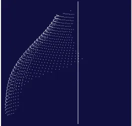
Figure 1. Vase point cloud.
Figure 2. The axis of rotation in line geometry.
3. Contour Calculation
countries, but the sampling point is only obtained from the intersection of a plane and a fragment of the axis of rotation, and the estimated contour of the is not accurate [9]. Based on PDM (Point Distance Minimization) the B-Spilne curve fitting method, 3D point cloud data of the method using only one plane and debris intersection point obtained are sparse, the sampling points and use the distance as error criterion fitting method is relatively poor, and due to the presence of noise, sampling point may all the features can not be completely retained the contour lines, and the fitting part of the lack of information [10]. Based on SDM (Square Distance Minimization) of the B-Spilne curve fitting method, the method of control polygon firstly with four binary tree to calculate the initial curve, then according to the curve between point cloud data and two-dimensional square distance control polygon adjustment curve continuously, fitting curves by two-dimensional point cloud data of the [11]. This method is a good method to fit the data of two-dimensional point cloud, which has fast speed and stable convergence [12].
Based on the SDM method, the outline of the outline of the general steps are: first of all the cultural relics of the three-dimensional point projection to a plane, x =
i 0 i 0
( - )P P ×I , y=(P P- ) .⋅I
Among:
0
P is based on a point calculation of rotation axis line geometry in the calculation of the shaft;
I is the unit direction vector of the rotation axis; I is the moment vector of the rotation axis;
i
P 3D points for fragmentation;
x, y for the three-dimensional point cloud data to the plane after the projection of the two-dimensional coordinates.
The x calculated by the formula is actually the distance from each vertex Pi to the axis of rotation, and y is the
projection of the Pi to the axis of rotation. The projection
results in the same circle (vertical axis of rotation and rotation of plane crossed by the parts of the circle is called the circle) corresponding to the same point in the plane coordinate system, so to get a set of 2D point clouds [13]. Then, the SDM method is used to fit the point cloud with the B-Spilne curve to get the contour line.
Figure 3 is the fitting of the rotated contour line by the SDM method:
Figure 3. Rotary contour.
4. The Radius of Gyration and the
Calculation of the Angle of Fit
4.1. Calculation of Radius of Gyration
The axis of rotation and rotation of the contour line is calculated to calculate the rotation radius of rotation, first to calculate the rotation of the contour interval sampling (slicing), a rotating axis perpendicular to the axis of rotation of a series of equidistant line, the line and the intersection of the rotary contour intersection of straight line with the axis of rotation the distance (that is the center of a circle) is that each layer corresponding to the radius.
4.2. Matching Angle Calculation
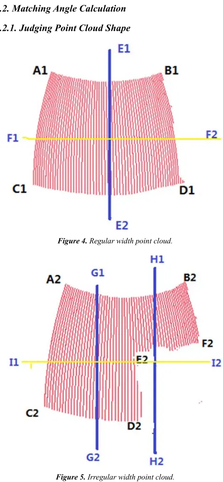
4.2.1. Judging Point Cloud Shape
Figure 4. Regular width point cloud.
Figure 5. Irregular width point cloud.
points along the vertical direction of the cloud layer (the yellow horizontal line represents a layer, that is, F1F2 and I1I1 layer), and then on each layer of the point cloud projection data points. In addition, need to find the middle position of each line segment cloud point E1E2 (the bus), to calculate each layer on the bus to the farthest point on both sides of the central angle (matching angle) [14]. In Figure 2, due to the symmetry of the point cloud, the center of a data point can be selected as the segmentation point when selecting the center line. As for the point cloud as shown in Figure 3, is to choose the line G1G2 or H1H2, you need to first determine the shape of the point cloud. For the point cloud in Figure 3, if you choose the subsection line H1H2, it does not pass through the point cloud of the lower part of the cloud, in the calculation of the two sides of the angle of cooperation, there will be errors, thus affecting the coordination effect. The piecewise line G1G2 is a better choice, it can ensure that each slice layer through the point cloud inside, it can be calculated from the point of view of the points on both sides of the coordination, so as to ensure the feasibility of subsequent calculations. In the judgment of the point cloud shape process, mainly through the judgment points to judge the whole part of the layer of point cloud shape trend, so as to select its horizontal center position as segment points in proper width, calculation principle such as formula (2):
i i
n N
η = (i = 1, 2, 3) (2)
In the formula, N is the total number of iterations plus 1, ni
is for the whole of the 10 layer (from the beginning of the twentieth layer, each layer of the increase in the number of points) to meet the number of cases (i = 1, 2, 3) under the number of layers,
η
i is corresponding to the proportion of niaccounted for N.
The algorithm steps are as follows:
(1) determine the number of iterations need N: according to a point cloud of layers, and set the 10 layer is calculated from the iteration step, the number of iterations of N.
(2) set the initial iteration variables: make the tenth level points is n0, and n1, n2 and n3 are zero.
(3) to determine the search rules and search: from the beginning of twentieth, every 10 increase of the number of layers and calculate the layer data points, when the layer points number was two times larger than n0, n3 automatically
add 1; when the layer points number is less than half of n0, n1
automatically add 1; otherwise, n2 automatically add 1.
(4) according to the formula (2), Calculating the proportion of n1, n2 and n3 inN, so as to determine the shape of the point
cloud, select the appropriate location of the narrow segment as a whole point cloud segmentation line.
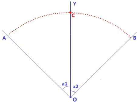
4.2.2. Calculation of Point Cloud Coordination Angle Figure 6 is a layer of point cloud projection, in the calculation of the matching angle, it is necessary to find the point cloud in the plane of the piecewise point C, and then calculated by the two part segment points corresponding to the
point cloud segmentation angle
∂
1 and∂
2. Among them, A points to the left of the piecewise point central angle corresponding to the maximum when the data points, and B points to the right end of the data points with piecewise point maximum angle.Figure 6. Coordination angle of a certain point cloud.
5. Using the Radius of Gyration and the
Angle of Cooperation to Coordinate
the Point Cloud
For the two points and divided into n1 and n2 layers of cloud points, each layer of the radius of gyration and fit angle data are as follows:
(1) the value of the radius of the two groups can be obtained from the two point clouds R1i (i = 1, 2, 3… n1) and R2j (j = 1, 2,
3... n2). Among them, R1i and R2j are the radius for the point
cloud 1 and point cloud 2 in the i and j layer.
(2) in addition, the corresponding values of the four groups can be obtained angle1i and angle2i (i = 1, 2, 3… n1 ), angle3j
and angle4j (j = 1, 2, 3... n2). Angle1i and angle2i are the angle
of fit on the i layer on the first point cloud; Similarly, angle3j
and angle4j are the angle of fit on the other layer of the point
cloud.
Using (1) and (2) in several groups of data, which can be calculated by the radius of features, so as to search two point cloud layer difference
ξ
, then use the matching angle features ultimately determine whether they are in the corresponding layer can be matched.6. Summary
position of the matching effect of each match, until the search results with the need, to get the matching layer, the angle value is checked, the realization of point cloud registration fragments.
References
[1] S. Ben Yacoub and Ch. Menard, Robust axis determination for rotational symmetric objects out of range data. Burger and Burge [Burge97], pages 197-201.
[2] R. Sablatnig and M. Kampel, Model-Based Registration of Front-and Backviews of rotational symmetric objects, Computer Vision and Image Understanding, 2002.
[3] R. Halir Estimation of the axis rotational of fragements of archaeological pottery, Burger and Burge [Burge97], pages 175-184.
[4] Zhang Zongxia. Research and implementation of classification and retrieval of cultural relic. Master Thesis of Shandong University, 2005.
[5] Pottmann, H., Peternell, M., Ravani, B., An introduction to line geometry with applications, Computer Aided Design 31, 1999, 3-16.
[6] Park H, Lee J. H. B-spline curve fitting based on adaptive curve refinement using dominant points [J]. Computer Aided Design, 2007, 39(6): 439-451.
[7] Saint-Marc P., Rom H., Medioni G., B-spline contour representment and symmetry detection [J]. IEEE Transactions on Pattern Analysis and Machine Inteligence, 1993, 15(11): 1191-1197.
[8] Li W., Xu S., Zhao G., et al. Adaptive knot placement in B-spline curve approximation [J]. Computer Aided Design, 2005, 37(8): 791-797.
[9] R. Sablatnig and M. Kampel, Model-Based Registration of Front-and Backviews of rotational symmetric objects, Computer Vision and Image Understanding (S1077-3142), 2002, 87(1-3): 90-103.
[10] Schindler K, Kampel M, Sablatnig R. Fitting of a Closed Planar Curve Representing a Profile of an Archaeological Fragement [C]. Proceedings of Proceedings of the 2001 conference on Virtual reality, archeology, and cultural heritage. Glyfada: ACM Press, 2001: 263-269.
[11] Wenping wang, Helmut Pottmann, Yangi Lu. Fitting B-spline Curves to Point Clouds by Square Distance Minimization [M]. ACM Transactions on Graphics (S0730-0301), 2006, 25: 214-238.
[12] Ouyang Leiguang. Cultural debris classification mosaic and parallel algorithm. Master's degree thesis of Shandong University. 2007.
[13] Zongfang Zhang. The estimation of the overall characteristics of the rotating object artifacts from point clouds. [J] Journal of Beijing Electronics Science and Technology Institute, 2008. [14] Qian Liu. Research and application of 3D contour line
matching pieces of cultural relics mosaic algorithm based on master's degree thesis of Northwestern University, 2013.
Biography
Zhu Hongguang was born in October 1991 in Henan Province. He has got a bachelor’s degree of Mechanical Manufacturing and Automation in Xinxiang University in 2015 and now he is a postgraduate in Shanghai University of Engineering Science.