1687
Fuzzy Based Approach For Direct Torque Control
Of Three Phase Induction Motor
K.B.Ravindrakumar, K.Karthick, D.Sivanandakumar, S.SivarajanAbstract— Induction machines have become very widely used in industrial and domestic applications due to their robustness, low cost and high efficiency. The induction machines are using simple structure for delivering mechanical power from electrical power. The need for variable exact driving speed of some industrial machines implies the use of speed control methods of induction machines. We can control its speed by using scalar or vector control method. One of the methods in vector control is Conventional Direct torque control (CDTC). The drawbacks of CDTC are high torque ripples, high ripples in flux and poor dynamic response. To overcome these drawbacks, in this paper we proposed the improved CDTC using fuzzy logic controller called Fuzzy Direct Torque Control (FDTC). It uses the simple relations between speed, torque, flux, and voltage to generate control voltages of a machine. The results of proposed method are validated using MATLAB/Simulink software.
Index Terms— Asynchronous motor, Direct torque control, DTC, Fuzzy logic, FDTC, Induction motor, Vector control.
—————————— ——————————
1 I
NTRODUCTION THE DC machines were broadly utilized for variable speed industrial applications as an effect of the decoupled control of torsion and flux that will be attained by independent control of armature and field current. DC drives has advantages in several factors like starting torque, simple management and nonlinear performance. DC machine-based drive systems are not majorly used in industrial applications because of the presence of commutator and brush arrangement in their construction [1]. The induction motor is the most used motor type in the industrial and domestic applications. These types of motors are preferred due to its simple and robust construction, reliability and has self-starting capability. Induction motors are also called asynchronous motor because the mechanical speed they offer is different from their electrical speed.Three phase induction motor is a single excitation motor whose stator winding is supplied from three phase source. The rotor of an induction motor gains its energy by means of induction from the stator. The three-phase voltage creates a rotating magnetic field in the air gap. This rotating field interacts with the windings of the rotor inducing voltage and current in it. The rotating field rotates at a constant speed of synchronization [2]. It forces the rotor to rotate generating mechanical torque at all speeds except for the synchronous speed. Induction motors can‘t run at synchronous speed, that‘s why they are also known as asynchronous machines. Induction motors are using a simple structure of electromechanical energy conversion. In the squirrel-cage motors, the rotor can‘t be
accessed under any condition. No need for brushes like in DC machines; or slip rings like in synchronous and wound AC machines [3]. This fact increases the use of induction motor in environments where the danger of fire exists. Because brushes and moving contacts cause sparks that can be a source of fire. Another dimension of strength in squirrel cage motors resides in the lack of wiring in their rotors. These rotors windings are built of strong bars that can withstand higher currents and work under heavy electrical and mechanical overloads.
Wound-rotor induction motors are less common in industry and used in limited applications where there is need for access to the rotor‘s circuit [4]. The rotor in these motors is provided with slip rings to give access to the moving windings from outside to add some external resistance to control the characteristics of the motor.
When the motor reaches its nominal speed, the external resistances can be removed, and the ends of the rotor‘s windings are short-circuited. Speed control of industrial motors is a very important subject due to the vital influence of speed on some applications [5]. Although squirrel cage motors are cheap in comparison with other six types of motors, their control is a bit costly. Different speed and torque control methods exist for induction motors. The speed control of motors implies the use of power electronic converters to provide the desired control of different parameters of voltage and frequency [6].
2. R
EVIEWO
FE
XISTINGW
ORKThe concept of direct torque control (DTC) is very advanced when compared with many other techniques. Many were implemented this technique in different ways. Some of the methods are flux compensated DTC of asynchronous motor drive for operation at low speed [7], DTC of asynchronous motors using three-level voltage source inverters (VSI) [8], global less torque ripple design for DTC of asynchronous motor drives [9], discrete control method of duty cycle for DTC of asynchronous based drives [10] and DTC of asynchronous motor using space vector modulation (SVM) [11]. In flux compensated DTC of asynchronous motor drives [7], a new sensor less asynchronous motor drive which
————————————————
K.B.Ravindrakumar, Professor, Department of EEE, Vel Tech Multi Tech Dr.Rangarajan Dr.Sakunthala Engineering College, Avadi, Chennai. E-mail id: [email protected]
K.Karthick, Associate Professor, Department of EEE, GMR Institute of Technology, Rajam.
E-mail id: [email protected], [email protected]
D.Sivanandakumar, Assistant Professor, Department of EEE, Erode Sengunthar Engineering College, Erode.
E-mail id: [email protected].
1688 utilizes an adaptive observer of flux for speed assessment and
discrete-time DTC method for torque and stator field control. The type of observer requires a model of mechanical to advance the speed estimation for the duration of speed transients. The assessed stator field of the adaptive observer is utilized in the discrete-time DTC method to offer fast response in torque and free from ripple in the operation over the wide speed range. From this technique, it is seen that there is only a small speed estimation error during the speed transient. The sensor less drive can operate at high speed and the dynamic performance is very good, both during transient operation and steady state operation.
In DTC of induction motors using three-level VSI [8], the technique to produce the torque by stator flux compensation in effective way that makes the DTC applicable to asynchronous electrical drives in the operating region at low speed. Instead of indirectly estimating the stator resistance to compensate the stator flux, this study directly uses the speed error to compensate the stator flux without identifying the stator resistance when the motor is being operated at low speeds.
The flux compensator is effective only in the operating region at low speed, because in the high-speed region the estimated stator flux is precise enough so that the DTC switching table can output a proper voltage vector. The flux compensator is activated only when speed error always exists. Once the speed error is reduced, the flux compensated DTC is the same as the usual DTC. In global low torque ripple design for DTC of asynchronous motor drives [9], a control strategy for asynchronous motors based on DTC is described that applies a three-level inverter in its place of the regular two-level inverter.
The stator currents harmonic distortion and the power semiconductor switching frequency are also minimized in the proposed system. The three-level VSI has merits over the standard two-level VSI such as a more level in the output voltage, low harmonic distortion, and low switching frequency.
In discrete duty cycle based control method for DTC of asynchronous motor drives with model predictive solution [10], they proposed a DTC which provides a global less torque ripple, which satisfies the root-mean-square torque ripple criteria. The global less torque ripple DTC is a two-step design. The first step derives the torque error to zero at the end of the control period. Then, the next step minimizes the torque bias and rms ripple by changing the voltage vector asymmetry pattern in switching of the first step into symmetry ones. The common concept to reducing the torque ripple is the synthesis of a higher amount of voltage space vectors with respect to those used in basic DTC techniques. In DTC of asynchronous motor using SVM [11], they proposed a new duty cycle based control technique to minimize torque and flux ripples of the conventional DTC.
A new approach is presented to choose the suitable voltage vector and by implanting the zero- voltage vector along with the chosen one. Lower torque and flux ripples are achieved in this method. The implementation of conventional DTC using above methods are hard to implement and has some drawbacks. To get better performance, fuzzy logic based controller has been presented to replace the hysteresis
controller and switching table in conventional DTC. The fuzzy logic based controller is planned to have three inputs and one output. It determines the desired inverter vector state. The fuzzy logic-based DTC is very easy to implement, and it reduces the torque and stator flux ripples in induction motor drive.
2.1 Vector Control Techniques
Vector control has become the most popular control method of induction machines during the last 20 years. Vector control enables induction machines to be utilized in applications where DC machines used to be applied in the past [12]. The advantages of induction machines over DC machines are lower cost of purchase and maintenance, better reliability in hostile environment, higher efficiency, simplicity, ruggedness, absence of brushes, etc. However, vector control method requires more hardware and software than the control system of DC machines.
Vector control principles utilize reference frame transformation to refer three phase quantities to a rotating reference frame with fictitious direct and quadrature axes. In simple terms, vector control can be defined as a set of control algorithms that enable conversion of an AC machine into its equivalent DC machine counterpart from the control point of view.
The main characteristic of vector control is the independent and indirect control of torque and flux by two components d and q of the stator current in a rotating reference frame [13]. However, this is achieved by using co-ordinate transformation and current control loops, which make the control system more complicated. The main characteristics and shortcomings [14] of vector control may be summarized as follows.
In addition to other controllers, current controllers (in stationary or rotating reference frame) are required.
At least one co-ordinate transformation has to be executed on-line, in real time.
A separate PWM block is required for the inverter control.
A decoupling circuit is required, unless rotor flux-oriented control with current control in stationary reference frame is used.
A precise estimate of the instantaneous position of the selected flux space vector is necessary.
All the schemes are to some extent affected by variation of induction machine parameters.
There are different vector control methods of an induction machine. Among which DTC is one of best possible solution for variable frequency drives to control the torque and speed of induction motors.
3. F
UZZYB
ASEDA
PPROACHF
ORD
IRECTT
ORQUEC
ONTROLThe optimal voltage vector is selected to limit the torque and flux errors within the hysteresis bands. The advantages of this control method are rapid response of torque in transient operation and enhancement in the steady state efficiency. The conventional DTC has high torque ripples and poor dynamic response [15].
1689 Induction motors are the best in these drives [16]. So active
control of asynchronous motor parameters like speed, torque and flux are of utmost importance. The machine learning algorithms applied in other applications [17-20] can also be used for speed control with certain modifications. From the study of the control approaches, it is identified that torque control of AC motor could be accomplished according to various methods ranging from low-cost Volts/Hz ratio approach to sophisticated sensor less based vector control method. But every scheme has its disadvantages like losses, the requirement of separate current control loop, coordinate transformation, current ripple and torque etc. In this work, the principles of DTC method combined with artificial intelligent controller based on fuzzy logic will be discussed and used. The controller with DTC control will be simulated on an induction machine of squirrel type under different conditions.
3.1Principle of Vector Control
The block diagram of basic approach is shown in figure 1. The output from the model is given to the controller which convert these signals back to the AC form to fed the induction motor. The motor phase currents 𝑖𝑎, 𝑖𝑏, 𝑖𝑐 are converted to 𝑖𝑑𝑠𝑠 and 𝑖𝑞𝑠𝑠 in the stationary reference frame. These are then converted to the synchronously rotating reference frame d-q currents, 𝑖𝑑𝑠 and 𝑖𝑞𝑠. In the controller, two transformations are performed i.e. Clarke and Park transformation.
Fig. 1. Vector control implementation principle with machine 𝒅𝒆-𝒒𝒆 model
a) Clarke transformation
Transformation from 3 phase to 2 phase stationary axes 𝑖𝑠𝛼 and 𝑖𝑠𝛽. A 3-phase symmetrical machine is deliberated with stationary a-b-c axes at 1200 difference as shown in figure 2.
Fig. 2. Axis transformation from as-bs-cs to 𝒊𝒔𝜶- 𝒊𝒔𝜷
The above projection modifies the three -phase system into the (α, β) two-dimension orthogonal system as stated below
𝑖𝑠𝛼=𝑖𝑎 (1)
𝑖𝑠𝛽 = (2)
The voltages 𝑣𝑎𝑠, 𝑣𝑏𝑠, 𝑣𝑐𝑠 are the voltages of as, bs, cs phases consecutively. Now if the stationary axes 𝑖𝑠𝛼 and 𝑖𝑠𝛽are tailored
at angle θ as shown and the voltages across 𝑖𝑠𝛼 and 𝑖𝑠𝛽 axes to be 𝑣𝑑𝑠𝑠 and 𝑣𝑞𝑠𝑠 consecutively, the two-phase stationary voltages can be transformed to 3 phase voltages based on math equations as follows:
𝑣𝑎𝑠=𝑣𝑞𝑠𝑠cos 𝜃+𝑣𝑑𝑠𝑠sin 𝜃 (3) 𝑣𝑏𝑠=𝑣𝑞𝑠𝑠 cos (𝜃 − 120°) + 𝑣𝑑𝑠𝑠sin (𝜃 − 120°) (4) 𝑣𝑐𝑠=𝑣𝑞𝑠𝑠 cos (𝜃 + 120°) + 𝑣𝑑𝑠𝑠sin (𝜃 + 120°) (5) The phase voltages in matrix form can be written as:
= (6)
By inverse transformation, 𝑣𝑑𝑠𝑠 and 𝑣𝑞𝑠𝑠 can be written in terms of three phase voltages in matrix form as follows:
(7)
Where = zero sequence component.
b) Park transformation
Transformation from 2 phase stationary to 2 phase synchronous rotating frame of
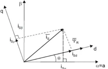
reference. The stationary axes 𝑖𝑠𝛼 and 𝑖𝑠𝛽 are translated to 𝑖𝑠𝑑 and 𝑖𝑠𝑞 synchronous rotating frame of reference that is moving with speed 𝜔𝑒 w.r.t axes 𝑖𝑠𝛼 and 𝑖𝑠𝛽 by the use of figure 3.
Fig. 3. Transformation from stationary α-β frame to synchronous rotating frame d-q
Here, θ is the rotor flux position. The torque and flux components of the current vector are determined by the following equations:
𝑖𝑠𝑞=𝑖𝑠𝛽 cos 𝜃+𝑖𝑠𝛼 sin 𝜃 (8) 𝑖𝑠𝑑=𝑖𝑠𝛼cos 𝜃+𝑖𝑠𝛽 sin 𝜃 (9)
The voltages 𝑣𝑑𝑠𝑠 and 𝑣𝑞𝑠𝑠 can be transformed to voltages on axis 𝑖𝑠𝑑 and 𝑖𝑠𝑞 based on the below equations:
𝑣𝑑𝑠=𝑣𝑞𝑠𝑠 cos(𝜃𝑒) - 𝑣𝑑𝑠𝑠sin(𝜃𝑒) (10) 𝑣𝑞𝑠=𝑣𝑑𝑠𝑠 cos(𝜃𝑒) + 𝑣𝑞𝑠𝑠sin(𝜃𝑒) (11)
The rotating frame arguments to stationary frame transformation is given in below equations:
𝑣𝑞𝑠𝑠= 𝑣𝑞𝑠 cos(𝜃𝑒) + 𝑣𝑑𝑠sin(𝜃𝑒) (12) 𝑣𝑑𝑠𝑠= −𝑣𝑞𝑠sin(𝜃𝑒) + 𝑣𝑑𝑠cos(𝜃𝑒) (13)
3.2 Results and Discussion
1690 presented. A fuzzy logic controller will be used to increase the
stability of system in transient and steady states of the machine. This chapter of the work is sacrificed for the study and discussion of the proposed control methods and the comparison between the obtained results. All results will be
presented and tabulated. During this work, a
MATLAB/Simulink standard three phase induction motor was used. The parameters of the motor are all given in table 1.
TABLE 1.PARAMETERS OF THE THREE-PHASE INDUCTION MOTOR
Motor Type Squirrel cage
Power 60 kVA
Voltage 415 V Frequency 50 Hz Mutual L 10 mH Inertia 3.1 kg.𝑚2 Stator L 0.3 mH Stator R 0.148 Ω Rotor L 0.3 mH Rotor R 0.0093 Ω
Poles 4
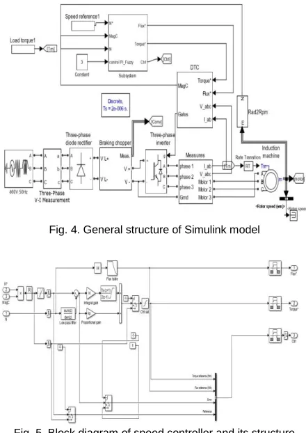
Three phase power source, three phase bridge rectifier, breaking chopper, and a three-phase VSI were used to supply the induction motor with the need power. General model of the simulation circuit is presented in figure 4. The rectifier is used to supply with DC voltage that is fed to a chopper. The chopper makes sure that the voltage at the DC side of the rectifier/inverter doesn’t exceed certain limit. The inverter is responsible to generate three-phase AC control voltages.
In this model, two controller types were used namely PI controller and fuzzy logic controller. These two controllers are used as seen in figure 5 & 6 to control the speed of the induction motor.
The reference speed slope is firstly adjusted to avoid any sudden changes in the speed. Sudden speed changes can’t be obeyed due to the slow response of motors compared to the other electronic devices. The reference speed is then compared with the measured actual speed of the motor to generate the input of the controller. The error is then fed to the controller to generate the suitable torque value that the motor should generate to make the error zero.
Figure 7 presents the Simulink model of the DTC. It contains blocks for torque and flux calculation, hysteresis of torque and flux, output voltage vector decision block and the gate pulse generation block. The contents of hysteresis block are presented in figure 8. It generates 3 different output levels for the torque and two levels for the flux. In figure 9 the transformations, torque, and flux calculation are presented.
Fig. 4. General structure of Simulink model
Fig. 5. Block diagram of speed controller and its structure
Fig. 6. Simulink model of Fuzzy logic controller
1691 Fig. 8. Flux and Torque hysteresis block
Fig. 9. Torque and flux calculation block
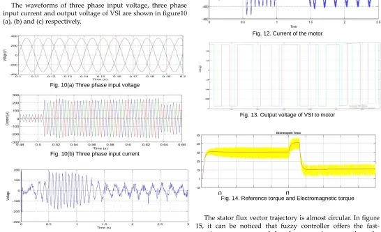
The waveforms of three phase input voltage, three phase input current and output voltage of VSI are shown in figure10 (a), (b) and (c) respectively.
Fig. 10(a) Three phase input voltage
Fig. 10(b) Three phase input current
Fig. 10 (c) Output voltage of VSI
3.3. Simulation Analysis of DTC drive with PI and Fuzzy Controller
In this model, different set speeds and different load torques were applied on the motor. PI controller is still able to show good results and small errors. Figure 11 presents the speed of the motor. Figure 12 and 13. present the current and line voltage generated by the VSI. Figure 14 presents the torque of the motor.
Fig. 11. Desired and actual rotor speed in case of PI controller
Fig. 12. Current of the motor
Fig. 13. Output voltage of VSI to motor
Fig. 14. Reference torque and Electromagnetic torque
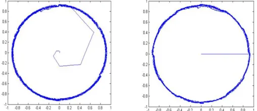
The stator flux vector trajectory is almost circular. In figure 15, it can be noticed that fuzzy controller offers the fast-transient responses and has better performance than the CDTC method.
0. 1
0.
1692 Fig. 15. Stator flux vector trajectory (a) CDTC (b) FDTC
Fig. 16. Torque response (a) CDTC (b) FDTC (c) Conventional and fuzzy DTC
Fig. 17. Response of stator flux magnitude (a) CDTC (b) FDTC (c) Comparison
Figure 16 and 17 presents the torque and stator flux response of both CDTC and FDTC and compared between those results. It is clear that the fuzzy logic controller is faster in response with less transient fluctuations.
4. CONCLUSION
The control of induction motors using DTC method with fuzzy logic controller is simple, efficient, with the output of desired values of speed and torque. The DTC was combined with PI controller for speed regulation. PI controllers are
considered the most commonly applied controllers in industry due to their simple functional principles and the ease of their implementation. The use of fuzzy controller was proposed in this work to increase the accuracy of speed results in addition to the ability of fuzzy logic controller to react against sudden changes and non-linearity of the system. Fuzzy controller has proved its efficiency and good results when used with conventional DTC control scheme. The method implies no closed loop control of the VSI. From the obtained results we can conclude that fuzzy logic controller with DTC method is a very excellent choice for the control of induction machines in term of low cost, simplicity, and efficiency. Improved results with sudden changes in the desired speed were achieved by replacing the traditional PI controller by a nonlinear fuzzy logic controller. That is, higher stability of the control system and the machine is achieved in addition to fast and exact system response.
R
EFERENCES[1] Karthick, K & Chitra, S 2016, ‗Performance Prediction of DC Constant Flux Machine Using Optical Character Recognition‘, Asian Journal of Research in Social Sciences and Humanities, Asian Research Consortium, vol. 6, no. 6, pp. 78-90, ISSN 2249-7315.
[2] Uma Sabareesh, V & Karthick, K 2019, ‗Solar PV based Permanent Magnet Synchronous Motor Drive for Water Pumping Application‘, International Journal of Innovative Technology and Exploring Engineering (IJITEE), Blue Eyes Intelligence Engineering & Sciences Publication, Vol. 8, No. 9, pp. 837-843.
[3] S. M. Tripathi and R. Vaish, "Taxonomic research survey on vector controlled induction motor drives," in IET Power Electronics, vol. 12, no. 7, pp. 1603-1615, 19 6 2019.
[4] M. R. Barusu, U. Sethurajan and M. Deivasigamani, "Non-invasive method for rotor bar fault diagnosis in three-phase squirrel cage induction motor with advanced signal processing technique," in The Journal of Engineering, vol. 2019, no. 17, pp. 4415-4419, 6 2019.
[5] N. B. b. Ahamad, C. Su, X. Zhaoxia, J. C. Vasquez, J. M. Guerrero and C. Liao, "Energy Harvesting From Harbor Cranes With Flywheel Energy Storage Systems," in IEEE Transactions on Industry Applications, vol. 55, no. 4, pp. 3354-3364, July-Aug. 2019.
[6] M. K. Metwaly, H. Z. Azazi, S. A. Deraz, M. E. Dessouki and M. S. Zaky, "Power Factor Correction of Three-Phase PWM AC Chopper Fed Induction Motor Drive System Using HBCC Technique," in IEEE Access, vol. 7, pp. 43438-43452, 2019. [7] Kuo-Kai Shyu, Li-Jen Shang, Hwang-Zhi Chen and Ko-Wen
Jwo, "Flux compensated direct torque control of induction motor drives for low speed operation," in IEEE Transactions on Power Electronics, vol. 19, no. 6, pp. 1608-1613, Nov. 2004. [8] X. del Toro Garcia, A. Arias, M. G. Jayne and P. A. Witting,
"Direct Torque Control of Induction Motors Utilizing Three-Level Voltage Source Inverters," in IEEE Transactions on Industrial Electronics, vol. 55, no. 2, pp. 956-958, Feb. 2008. [9] Tatte, Y. & Aware, M., ―Torque ripple reduction in direct torque
1693 [10]M. R. Nikzad, B. Asaei and S. O. Ahmadi, "Discrete
Duty-Cycle-Control Method for Direct Torque Duty-Cycle-Control of Induction Motor Drives With Model Predictive Solution," in IEEE Transactions on Power Electronics, vol. 33, no. 3, pp. 2317-2329, March 2018. [11]Ammar, A., Bourek, A. & Benakcha, A. J Control Autom Electr
Syst (2017) 28: 189. https://doi.org/10.1007/s40313-016-0294-7. [12]Ľuboš Struharňanský, Ján Vittek, Pavol Makyš, Jaroslav
Ilončiak, ―Vector Control Techniques for Traction Drive with Induction Machines – Comparison‖, Procedia Engineering, Vol. 192, 2017, Pages 851-856, ISSN 1877-7058, https://doi.org/10.1016/j.proeng.2017.06.147.
[13]S. Hussain and M. A. Bazaz, "Review of vector control strategies for three phase induction motor drive," 2015 International Conference on Recent Developments in Control, Automation and Power Engineering (RDCAPE), Noida, 2015, pp. 96-101. [14]D. Telford, M. W. Dunnigan and B. W. Williams, "A comparison
of vector control and direct torque control of an induction machine," 2000 IEEE 31st Annual Power Electronics Specialists Conference. Conference Proceedings (Cat. No.00CH37018), Galway, Ireland, 2000, pp. 421-426 vol.1. doi: 10.1109/PESC.2000.878893
[15]V. P. Muddineni, S. R. Sandepudi and A. K. Bonala, "Conventional and model predictive direct torque control techniques for induction motor drive," 2016 IEEE 1st International Conference on Power Electronics, Intelligent Control and Energy Systems (ICPEICES), Delhi, 2016, pp. 1-6. doi: 10.1109/ICPEICES.2016.7853287
[16]J. Rodríguez-Reséndiz, J. M. Gutiérrez-Villalobos, D. Duarte-Correa, J. D. Mendiola-Santibañez, I. M. Santillán-Méndez, ―Design and Implementation of an Adjustable Speed Drive for Motion Control Applications‖, Journal of applied research and technology, Vol. 10, No.2, pp.180-194, April 2012.
[17]Karthick, K & Kavaskar, S 2019, ‗Text detection and Recognition in Raw Image Dataset of Seven Segment Digital Energy Meter Display‘, Energy Reports, Elsevier. Vol. 5, November 2019, pp. 842-852, (ISSN 2352-4847)
[18]Karthick, K & Chitra, S 2017, ‗Novel Method for Energy Consumption Billing Using Optical Character Recognition‘, Energy Engineering: Journal of Association of Energy Engineers, Taylor & Francis, vol. 114, no. 3, pp. 64-76, ISSN:1998595.
[19]Karthick, K, Ravindrakumar, K.B., Manikandan, R & Cristin, R 2019, ‗Consumer Service Number Recognition Using Template Matching Algorithm for Improvements in OCR Based Energy Consumption Billing‘, ICIC Express Letters, Part B: Applications, ICIC International, Vol. 10, No. 10. October 2019. [20]Karthick, K, Ravindrakumar, K.B., Francis, R. and Ilankannan, S