Published online September 30, 2014 (http://www.sciencepublishinggroup.com/j/ijssn) doi: 10.11648/j.ijssn.20140204.11
Estimation of errors caused by spherical approximation of
earth shape in radio emitters position fixing process using
direction finding
Viacheslav Volodymyrovych Kalugin, Anatoliy Heorhievych Kochergin
*,
Olexandr Volodymyrovych Chebotov
Scientific-Engineering Center of Radio Engineering Systems Ltd (NTC RTS AN PRE), Vosstania sq., 7/8, Kharkiv, 61001, Ukraine
Email address:
[email protected] (A. G. Kochergin)
To cite this article:
Viacheslav Volodymyrovych Kalugin, Anatoliy Heorhievich Kochergin, Olexandr Volodymyrovych Chebotov. Estimation of Errors Caused by Spherical Approximation of Earth Shape in Radio Emitters Position Fixing Process Using Direction Finding. International Journal of Sensors and Sensor Networks. Vol. 2, No. 4, 2014, pp. 31-36. doi: 10.11648/j.ijssn.20140204.11
Abstract:
Accuracy improving of radio emitter position fixing is sufficient in the field of radiomonitoring, communication intelligence, radionavigation and radiogeodesy. This paper represents results of errors estimation in radio emitter position fixing process applying spherical approximation of the Earth surface obtained by means of numerical simulation. Study of values of these errors was paid little attention in scientific literature. Besides that there are no indications as for development and implementation of algorithms accounting for Earth spheroid shape. In presented article it is shown that for improving accuracy of position fixing on spreading radio paths it is necessary to take into consideration Earth surface shape. Realization of position fixing algorithms accounting earth spheroid shape revealed their high efficiency in real RDF networks. Software realizing these algorithms is implemented in several production prototypes of RDF networks.Keywords:
Direction Finding, Spheroid, Radio Emitter, Position Fixing1. Introduction
Theoretical basis for solving task of position fixing (PF) of objects on the Earth surface by the goniometric measurement data was obtained due to development of practical geodesy and navigation. This task is called direct azimuth intersection of bearing lines. If azimuths of object Ai are measured from N points with known coordinates Bi,Li, coordinates of object B,L (latitude and longitude respectively) are defined from system of equations solution
. ,..., 2 , 1
), , , , (
N i
L B L B f Ai i i
= =
(1)
Form of these equations is defined by the Earth surface shape. It is known, that Earth surface shape, called spheroid is sufficiently enough circumcised by shape of ellipsoid of revolution (also known as reference ellipsoid) flattened at the poles, difference between sizes of the its semiaxes comprises about 43 km. Parameters of Earth ellipsoid providing accuracy to a part of a meter at any distances are known in
solving geodesic tasks.
Solution of task of direct azimuth intersection of bearing lines implementing radio direction finders (RDF) is reduced to finding ray intersections on Earth shape [1] what by its turn needs solution of inverse geodesic problem [2].
If Earth surface had strictly spherical shape, rays were great circle arcs, and system of equations (1) was presented as a system of trigonometric equations, which solution can be easily obtained by means of progressive approximation/iteration.
1) calculation of integral by one of the methods of progressive approximation;
2) expansion in series of integrals themselves integrands with successive termwise integration of every series;
3) projection by any method of geodesic lines to the sphere and solving of the task on the sphere with following conversion of obtained spherical coordinates into geodesic coordinates.
When electronic computers appeared necessity in solution of direct azimuth intersection of bearing lines task already existed, but considering low efficiency of electronic computers of first generation the third method was applied in simplified version only, called procedure of correspondence by normal, where B,L were simply equated to spherical coordinates ϕ,λ . For correct solution implementing this procedure it is necessary to reduce measured geodesic azimuths Ai to corresponding them azimuths on spherical surface αi [3], however for the most part of algorithms realized in practice this is neglected and azimuths on ellipsoid and sphere are considered to be equal. Such assumption is called spherical approximation of Earth surface.
Let ϕi,λi - be coordinates of radio direction finders,
obtained by means of spherical approximation on the sphere,
λ
ϕ, - unknown coordinates of radio emitter. When connection of azimuth of
i
-th segment of great circle arc αi and coordinates of its beginning ϕ, and end λ ϕi,λi (latitude,longitude respectively) is defined on the sphere by the equation [4]
) sin
sin /
(cos i i i i
i arctg ϕtgϕ γ ϕctgγ
α = − , (2)
where γi=λ−λi i=1...N , N - number of azimuth determinants (RDF).
Equations (2) in navigation marine vehicles are called equations of navigation isoline, determining locus of points of equal navigation parameter values, in this case – azimuth.
For solving task of object PF by N measured azimuths it is necessary to solve system of equations (2), where ϕ, - λ desired coordinates, ϕi,λi - known point coordinates of RDF location. When N>2 this system contains redundant number of transcendental equations, in general case, incompatible, as a result of bearing errors presence. When solving similar tasks in geodesy [4] and navigation [5] resort to linearization of system of equations (2) with following implementation of weighted least squares (WLS) method [6]. The task comes to iterative solution of the system of two linear equations with two unknown corrections ∆ϕ and ∆λ
to calculated at the previous step coordinates. This system of equations has the form
∑
∑
∑
∑
∑
∑
= = = = = = = + = + N i i i i N i i i N i i i i N i i i i N i i i i N i i i l b p b p ∆ b a p ∆ l a p b a p ∆ a p ∆ 1 1 2 1 1 1 1 2 λ ϕ λ ϕ (3)where: ai, bi - partial derivatives of system of the functions (2) by latitude and longitude respectively; li=αi−αic - difference between measured bearings and bearings calculated at the previous step; pi - weights of measurings, inversely proportional to bearing RMS estimations. Calculations are done till corrections become negligible.
General computational layout when solving task of PF on the Earth ellipsoid surface doesn’t differ from abovementioned layout. The main difference consists in corrections of measured azimuths for conversion from ellipsoid to sphere and in the form of system of equations (3). Technique for solving task of direct azimuth intersection of bearing lines is described in [1].
Estimation of Errors Caused by Spherical Approximation of Earth Shape in Radio Emitters Position Fixing Process is a subject of concern. Derivation of analytical dependencies for determination of these errors is impossible in practice; therefore their estimation is done implementing numerical simulation.
Four models were developed for estimation these corrections.
2. Simulation Results
2.1. Model of Ideal RDF Disposition Relative to RE Position without Instrumental Bearing Errors and Errors Caused by Peculiarity of Radio Waves Propagation
The first model is developed in the following way.
On the surface of the Earth ellipsoid RE with preset coordinates and direction finding network containing preset number of RDF arranged equidistantly by azimuth around RE are located (an exception is the case of two RDF when the central angle between them equals 90 degrees). It is known that such arrangement of RDF relative to RE from the point of view of minimal PF error is ideal.
Then RE bearings on ellipsoid surface are calculated and considering geodesic RDF coordinates and RE bearings being equal to spherical RE bearings and spherical coordinates of RDF system of equations on sphere is solved using WLS method, that means that most probable coordinates of source point is determined. Then distance on ellipsoid between preset and calculated RE coordinates defining PF error. After that orientation of RDF network relative to the meridian is changed and the process is repeated.
Figure 1. PF errors dependence on orientation of network consisting of two RDF. Latitude of RE disposition – 30°, distance – 2500 km
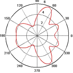
Figure 2. PF errors dependence on orientation of network consisting of three RDF with equidistant circular arrangement. Latitude of RE disposition – 30°, distance – 2500 km
Figure 3. PF errors dependence on orientation of network consisting of two RDF. Latitude of RE disposition – 40°, distance –500 km
Figure 4. PF errors dependence on orientation of network consisting of three RDF with equidistant circular arrangement. Latitude of RE disposition – 40°, distance – 500 km
Figure 5. PF errors dependence on orientation of network consisting of five RDF with equidistant circular arrangement. Latitude of RE disposition – 40°, distance – 500 km
Figure 6. PF errors dependence on orientation of network consisting of two RDF. Latitude of RE disposition – 40°, distance – 2500 km
Figure 7. PF errors dependence on orientation of network consisting of three RDF with equidistant circular arrangement. Latitude of RE disposition – 40°, distance – 2500 km
Figure 9. PF errors dependence on orientation of network consisting of three RDF with equidistant circular arrangement. Latitude of RE disposition – 50°, distance – 2500 km
On this patterns radial coordinate corresponds to PF error value in km, azimuthal coordinate corresponds to orientation of RDF network relative to the meridian in degrees. Patterns are constructed for different latitude of RE disposition, distances and number of RDF.
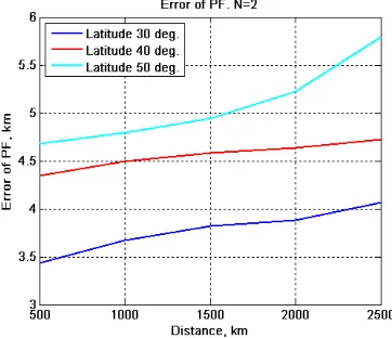
Maximal PF error dependences on distance are presented on figures 10 – 12, they are constructed from complete set of polar diagrams obtained during simulation for different latitudes of RE disposition and different number of RDF arranged in a circle with radius being equal to distance.
Figure 10. Maximal PF error dependence (km) on distance to RE in the network consisting of two RDF. Latitude of RE disposition – 30°, 40°, 50°
Figure 11. Maximal PF error dependence (km) on distance to RE in the network consisting of three RDF. Latitude of RE disposition – 30°, 40°, 50°
Figure 12. Maximal PF error dependence (km) on distance to RE in the network consisting of different number of RDF. Latitude of RE disposition – 40°
Maximal PF error dependency on arc length in degrees between two last RDF for N=2 и N =3is presented on figure 13.
Figure 13. Maximal PF error dependence on arc length in degrees between last RDF with different number of RDF. Latitude of RE disposition – 40°, distance – 2500 km
Presented results allow estimating of order of possible error PF values, stipulated by spherical approximation for ideal RDF network.
Notice, that in the abovementioned model like in the second and fourth models described further instrumental errors and bearing errors caused by peculiarity of radio waves propagation due to ionosphere influence when reflecting signals, are considered to be absent. Error caused by spherical approximation is present in all four models.
2.2. Model of Real Disposition of RDF and RE with Instrumental Errors and Bearing Errors Caused by Peculiarities of Radio Wave Propagation being Absent
direction finding process was simulated in HF band with radiosignals being reflected from ionosphere without presence of instrumental and bearing errors caused by peculiarities of radiowave propagation. Results of this simulation are presented in table 1.
Table 1. Summary of model simulations
RE disposition Mean error of PF, km
Tehran 2.7
Ankara 18.3
Baghdad 4.5
Karachi 7.6
Delhi 7.1
Islamabad 2.3
Mumbai 12.5
Kabul 1.7
2.3. Model of Real Disposition of RDF and RE with Instrumental Errors and Bearing Errors Caused by Peculiarities of Radio Wave Propagation being Present
For estimating simultaneous influence on accuracy of PF errors caused by spherical approximation, of instrumental errors and errors caused by radiowave propagation the third model is developed, where RDF and RE have the same dislocation as in the second model, and to measured bearings intermittent errors distributed by normal law are added.
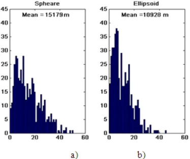
Simulation results are presented on diagrams of PF errors distribution. On figure 14 as an example one of obtained results is demonstrated. On this figure left histogram presents errors distribution of spherical approximation, the right one – of accurate solution of task on the Earth ellipsoid surface. In the first case mean value of error comprised 17.6 km, in the second case – 13.3 km.
Fig. 14. Histograms of PF errors distribution in km with real RDF RE dislocation with the presence of bearing errors: a) spherical approximation b) accurate solution
2.4. Model of Real Disposition of RDF and RE on Different Azimuths with Instrumental Errors and Bearing Errors Caused by Peculiarities of Radio Wave Propagation being Absent
The fourth model is developed in order to provide
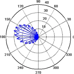
estimation of errors caused by spherical approximation for conditional disposition of RDF on real territory and RE dislocation in various directions. Disposition of RE was simulated at the distance of 2500 km from RDF number 1 on the azimuths from 0° to 360° with instrumental errors and bearing errors caused by peculiarities of radio wave propagation being absent. Simulation results are presented on figures 15 – 19 in the form of polar patterns, where azimuth coordinate corresponds to RE azimuth relative to RDF number 1. Radial coordinate on figure 15 corresponds to PF error value in km, on figure 16 and figure 17 radial coordinate stands for error ellipse semimajor and semiminor axis size in km respectively, within the boundaries of this ellipse with the probability of 63% is a real location of, on figure 18 – area of this errors ellipse is given in sq. km.
On figure 19 hodograph of vectors is presented, it characterizes direction and offset value of calculated coordinates from true RE coordinates in km.
Figure 15. PF errors dependence on RE azimuth for true RDF disposition
Figure 16. Dependence of minor semiaxis of error ellipse length in km on RE azimuth for true RDF dislocation
Figure 18. Dependence of area of error ellipse in sq. km on RE azimuth for true RDF disposition
Figure 19. Hodograph of offset vectors of calculated coordinates relative to true RE coordinates in km for true dislocation of RDF with RE being located on different directions on distance of 2500 km
3. Conclusion
Basing on simulation results the following can be concluded:
1. PF error caused by spherical approximation of Earth surface shape depends on number and relative position of RDF and RE, and on latitude of RE location.
2. When number of RDF is more than 5 and they are ideally located relative to RE PF error value almost doesn’t depend on RDF network orientation relative to the Earth meridian (fig. 5).
3. In ideal RDF network when distance and latitude of RE location is increased and when arch length between the last RDF differs from the value of around 90 – 110°, PF error increases (fig. 10 – 13).
4. In ideal network when distance to RE is about 2500 km, with a presence of two bearings and RE latitude equal to 40 degrees, error can compose 5 km, (fig. 5) and when the arch length between the last RDF is about 20° (or 160°) – 9 km (fig. 13).
5. In real RDF network PF error caused by spherical
approximation for true coordinates of RDF and RE comprises from 1.7 km to 18 km (fig.15).
6. Coordinates calculated implementing spherical approximation in real RDF network are mostly shifted to south-south-east (fig. 19).
7. Maximal errors in real RDF network arise when RE is located in western direction. Probability ellipse in conditional RDF network is significantly prolate in north-western direction regardless of RE location; area of probability ellipse is also maximal in this direction (fig. 15, 17, 18).
8. Real RDF network possess not sufficiently wide goniobasis, that is why increased accuracy of direction finding and correct bearing rejection when position fixing are needed. In view of moderate number of RDF in the network the best algorithm for bearing rejection is rejection of not anomalous bearings but of anomalous points of bearing intersection.
9. PF errors caused by spherical approximation of Earth surface shape can be compared with instrumental errors and errors caused by peculiarity of radiowave propagation. Taking into consideration of spheroidal Earth surface shape allows reducing general PF error in real RDF network on true territory in general by 10 – 20%.
Operational tests of developed PF algorithms acconting for spheroidal Earth surface shape on true territory demonstrated their high efficiency.
References
[1] Z. Wartell. W, Ribarsky, L. Hodges, Efficient Ray Intersection with Global Terrain Using Spheroidal Heigh-Augmented Quadtrees. VisSym' 99, Joint EUROGRAPHICS-IEEE TCCG Symposium of Visualisation, May 26-28, 1999, in Vienna, Austria.
[2] L. E. Sjöberg, M. Shirasian, Solving the Direct and Inverse Geodetic Problems on the Ellipsoid by Numerical Integration, Journal of Surveying Engineering, Vol. 138, No. 1, 2012, pp. 9-16.
[3] T. Vincenty, Geometric Reduction of Measured Lines, Surveying and Mapping, Vol. 46, No 1, 1012, pp. 225-229. [4] G. I. Bomford, Geodesy, 4-th ed., Clarendon Press, Oxford,
1980.
[5] P. A. Cross, Advanced Squares Applied to Position-fixing, Working Paper No 6, University of East London, School of Surveying, January 1994.