Analysis and Design of Bowtie Antenna with
Different Shapes and Structures
Babita Harchandra#, Randhir Singh#
#Dept of E&C, Sri Sai College of Engineering & Technology, Badhani, Pathankot, Punjab- 145001, India
Abstract— The demand of compact, efficient and economical communication devices has been tremendously increased. Same demand has been observed in antennas for multi-band applications. In this work, different designs of bowtie antennas are studied. The proposed antennas are designed, and results are evaluated to study different output parameters. The results confirmed that the proposed antennas may be useful for different mobile communication systems and Wireless applications. The results showed sufficient isolation among the operating frequency bands with improvement in gain and directivity. The results obtained had showed better improvement in the return loss and radiation pattern in comparison to the other existing antennas.
Keywords— Microstrip patch antenna, insertion loss, multi-band,
mobile communication; bowtie antenna.
I. INTRODUCTION
In modern communication systems, light weighted, economical, compact, easy to carry and simple to use devices are in demand [1]. In this regard, the need of such antenna designs has been squeezed significantly by several researchers. To design an effective antenna, this becomes necessary to design it according to the theoretical calculations with proper external shapes and dimensions [2]. A microstrip element was invented and patented by Munson [3]. However, different microstrip geometries for antenna applications were studied by Weinschel [4]. The extensive work by Munson on the development of microstrip antennas gave birth to a new antenna industry [5]. During recent times, micromachining technology is developed that improves the antenna performance. Several methods have been reported to reduce the effective dielectric constant of substrate. High performance
couples to a resonant slot cut orthogonally in the upper conductor, the device is said to be a stripline radiator. In microstrip patch antennas, generally, two kinds of feeding are possible, i.e., coaxial probe feed and aperature coupled feed [10] [11]. Coaxial feed is the simplest feeding technique in microstrip antennas. In this, an inner conductor of coaxial line is attached to the radiating patch while outer conductor is connected to ground plane. It has spurious radiation because the radiating and feeding systems are disposed on two sides of ground plane and shielded from each other [12-14]. In aperature coupled feeding, the radiating patch is etched on the top of the antenna substrate and feed line is etched on the bottom of substrate. The thickness and dielectric constants of these two substrates may thus be chosen independently to optimize the distinct electrical functions of radiation and circuitry [15] [16].
In this work, a microstrip antenna with different bowtie arms is designed. Four different bowtie shapes were studied after theoretical analysis, i.e., parabolic bowtie, triangular bowtie, bow shaped, and circular shaped mirror arms. Aperture feed is used and the antennas are then analysed in accordance to the designed dimensions and geometries. Further, the designed antennas are evaluated for results in the form of output parameters.
II. ANTENNA GEOMETRY
rectangular patch. A lumped port excitation is used for the CPW feed. The dimensions of the proposed antennas are set using theoretical analysis. The output parameters depend on the distance, position and the orientation of the bowtie.
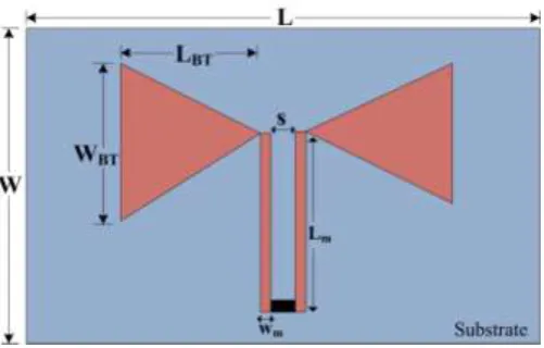
Fig. 1 Schematic showing shape and dimensional names of bowtie antenna
TABLE I
PARAMETERS AND DIMENSIONS OF THE PROPOSED BOWTIE ANTENNAS
Parameters Dimensions (mm) Length of the substrate, L 70
Width of the substrate, W 55 Bowtie arm length, LBT 23.6
Bowtie arm width, WBT 26
Spacing between feed line slots, s 6 Sot length, Lm 34
Slot width, Wm 1.2
Height of the substrate, h 1.6
The width, W and length, L of the patch are calculated by using the transmission line model. The width of the rectangular patch, W is given by using Equation
r 0 c w ( 1) 2f 2 (i)
The effective dielectric constant, can be obtained by using Equation
1 2
r r
reff
1 1 h
E 1 12
2 2 W
(ii)
The length extension of the patch, can be obtained by using equation
reff reff WE 0.3 0.264
h L 0.412h
W
E 0.258 0.8
h (iii)
The actual length of rectangular patch, L is calculated by using equation 0 2 eff reff c L f E 2 eff
LL L
(iv)
where Leff is the effective length and is calculated as
0 2 eff reff c L f E (vi)
For proper antenna designs, some finite ground plane is necessary below the substrate. Similarly, for practical design of microstrip patch antenna, it is essential that the ground plane should be greater than the actual patch dimensions by about six times the substrate thickness [14-16]. Thus, the dimensions of the ground plane may be given as
g
L 6hl
(vii)
g
W 6hw
(viii)
The input parameters of the microstrip patch antenna are estimated using these above equations.
III.RESULTS AND DISCUSSIONS
The proposed design is simulated on the computational machine with processing speed of 2.6 GHz and 4 GB RAM. The virtual memory used during simulation is 2.1 GHz. A precise sized meshing is not selected to avoid the computational load. Frequency domain setting is selected for simulating the model. The characteristic impedance (Z0) of the simulated design comes out to be 50 Ω.
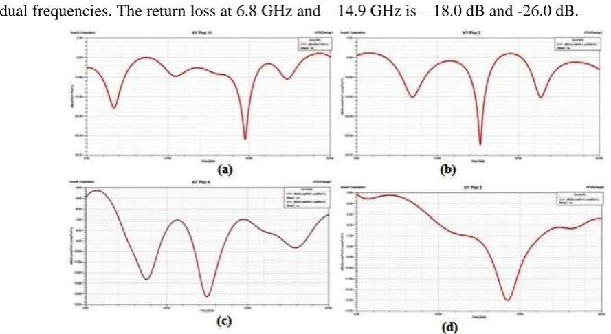
for dual frequencies. The return loss at 6.8 GHz and 14.9 GHz is – 18.0 dB and -26.0 dB.
Fig. 4 Graphs showing insertion losses of their respective antennas
The Figure 4(b) shows the insertion loss for triangular bowtie antenna with triple band applications. The return loss at 8.5 GHz, 12.6 GHz, and 16.4 GHz is – 15.05 dB, -27.50 dB, and -15.1 dB. Figure 4(c) shows the return loss of the bow shaped bowtie antenna. The return loss at 8.7 GHz
and 13.5 GHz is – 12.6 dB and -14.3 dB. Figure 4(d) shows the return loss of the single band circular bowtie antenna. The return loss at 14.3 GHz is –13 dB.
Figure 5 shows the gain in dB for different proposed antennas.
The electric field distribution characteristics indicate that all the resonant modes for different coaxial positions can be tuned and controlled independently. Results show that despite a small distortion, the radiation patterns are reasonably well enough to work in different frequency bands.
IV.CONCLUSIONS
In this paper, four different multi-frequency microstrip bowtie antennas are designed by using lumped port excitation with CPW feed. These antennas are used to design a single, dual, and triple, band antenna. This design is based on mono layer, single patch and does not require complex circuitry. The gain of the antenna is as high 9.01 dB and as smaller as -2.7 dB value of gain. The characteristic impedance is fixed and accurate at 50 ohm. The proposed antenna designs can handle mutli-frequencies by simply changing the bowtie shapes and covers lot of demanding frequency bands used in everyday communication systems.
REFERENCES
[1] Y. P. Zhang and J. J. Wang, "Theory and analysis of differentially-driven microstrip antennas, "IEEE Transactions on Antennas and Propagation, Vol. 54, pp. 1092-1099, 2006. [2] K. P. Yang and K. L. Wong, “Dual band circularly polarized
square microstrip antenna,” IEEE Trans. Antennas Propagat., Vol. 49, No. 3, 378–382, March 2001.
[3] E. Munson, “Single slot cavity antennas assembly,” U.S. Patent No. 3713 162, Jan. 23, 1973.
[4] H. D. Weinschel, “Progress report on development of microstrip cylindrical arrays for sounding rockets,” Physic. and Sci. Lab., New Mexico State Univ., Las Cruces, 1973.
[5] K. Buell, H. Mosallaei and K. Sarabandi, “A substrate for small patch antennas providing tunable miniaturization factor," IEEE Trans. Microwave Theory Tech., Vol. 54, 135-139, 2006. [6] D. M. Pozar, Microwave Engineering: Wiley Inter-science,
2006.
[7] R. Chair, C. L. Mak, K. F. Lee, K. M. Luk, A. A. Kishk, “Miniature wide-band half U-slot and half E-shaped patch antennas,” IEEE Transactions on Antennas and Propagation., Vol. 53, pp. 2645–2652, 2005.
[8] H. Nakano, K. Vichien, “Dual-Frequency Patch Antenna with a Rectangular Notch,” Electronics Letters, vol. 25, No. 16, pp. 1067-1068, 1989.
[9] S. Arya, S. Khan, C. Shan, P. K. Lehana, “Design of a Microstrip Patch Antenna for Mobile Wireless Communication Systems,” Journal of Computational Intelligence and Electronic Systems, Vol. 1, No. 2, pp. 178-182, 2012.
[10] A. Aslam, F. A. Bhatti, “Matching Technique for Microstrip Patch Antenna Using GCPW Feed,” International Conference on Emerging Technologies, pp. 66 – 69, 2009.
[11] R. Arora, A. Kumar, S. Khan, S. Arya, “Finite Element Modeling and Design of Rectangular Patch Antenna with Different Feeding Techniques,” Open journal of Antenna and Propagation, vol. 1, no. 1, 2013.
[12] S. Arya, S. Khan, C. K. Shan, P. Lehana, “Design of Small Integrated Antenna for Peer to Peer Wireless Communication,” International Journal of Mobile Network Communications & Telematics, Vol. 2, no. 3, pp. 11-20, 2012,
[13] R. Arora, A. Kumar, S. Khan, S. Arya, “Design Analysis and Comparison of HE shaped and E Shaped Microstrip Patch Antennas,” International Journal on Communications Antenna and Propagation, Vol. 4, no. 1, pp. 27-31, 2014.
[14] L. C. Tsai, "A Dual-Band Bow-Tie-Shaped CPW-Fed Slot Antenna for WLAN Applications," Progress In Electromagnetics Research C, Vol. 47, 167–171, 2014. [15] J. P. DeVilliers,and J.P.Jacobs,“Gaussian process modeling of
CPW-fed slot antennas,” Progress In Electromagnetics Research, Vol. 98, 233–249, 2009.
[16] C. Y. Huang, C. C. Lin, and W. F.Chen, “Multiple band-stop