LOAD CONTROL OF A 3-Ø
SELF- EXCITED ASYNCHRONOUS
GENERATOR
SUBRAMANIAN KULANDHAIVELU
Power Electronics and Drives Division, School of Electrical Engineering, VIT University Vellore, Tamil Nadu, India – 632 014
Dr. K. K. RAY
Senior Professor, Power Electronics and Drives Division, School of Electrical Engineering, VIT University Vellore, Tamil Nadu, India – 632 014
Abstract:
This paper describes the simulation based performance study of a 3-Ø self-excited asynchronous generator (SEASG) in constant power operation. A feed back voltage based controller by using a load control technique to control and retain the generator terminal voltage constant. This technique mostly used in uncontrolled hydro turbine driven induction generators in a stand-alone power generator. The results has been validate by the steady state equivalent circuit analysis of a 2.2kW, 415Volts, 4.7A, Star connected, 1440-rpm induction generator. The proposed study system has been simulated using Mat lab/Simulink version-7.0.The simulated results are presented.
Keywords: Asynchronous generator; simulation; load control technique.
1. INTRODUCTION
The usage of self-excited cage induction generator (SECIG) has been increasing due to fast depletion of non-conventional energy sources in particular Mini/Micro/Pico hydropower generation. Squirrel cage induction generator (SCIG) has emerged as a possible alternative to conventional generator in an isolated power generation because of its low cost, less maintenance and rugged construction [1]-[8]. The literature review concludes that the load characteristic of SEASG is drooping with increasing in load [9]-[18]. Therefore, it needs a suitable voltage regulator to maintain the terminal voltage constant. Prospective of different voltage control schemes involves in an induction generator described in details [19]. A summary of different type of electronic controller configuration used in hydropower generators presented in details [20].
Professor S.S. Murthy et al. [21]-[22] suggested a practical electronic load controller used in hydropower generators. The design and transient analysis of the self-excited induction generator with electronic load controller has been explained Bhim Singh et al. [23]–[26].
In constant power operation of a 3-Ø self-excited asynchronous generator [SEASG], d.c chopper fed resistive load controller is more suitable among others. Therefore, the authors chosen a d.c chopper circuit based load controller for this simulation study. Because the harmonic effects caused by the three-phase rectifier chopper circuit over the generator, not yet discussed so far. The aim of this work is to study the harmonic generation of the load controller over the induction generator in a stand-alone operation.
This paper organized in six sub-headings; Asynchronous generator operation of a 3-Ø cage induction machine has been reviewed, principle operation, load controller, basics of the load controller, control circuit have been includes in descriptions of the system in section - 2. Equivalent circuit analysis of the study system has been presented in section - 3. Simulation of the system explained in four. Discussion over the simulation results in subheading -5. Conclusion of this work described in section -6.
2. DESCRIPTION OF THE SYSTEM
Fig.1 shows a schematic arrangement of the proposed stand-alone power generation scheme with asynchronous generator. It consists of a 5Hp, 220V, 20A, 1500/1700 rpm separately excited dc motor, 3-Ø induction motor, excitation capacitor bank (CE) along with the load controller, which consist of a 3-Ø diode
Fig.1 Proposed study system of 3-Ø self-excited asynchronous generator with load controller
2.1. Working Principle
An induction motor could operate, as generator in negative slip. This is a well-known concept. Therefore, An induction motor runs above the synchronous speed by the separately excited d.c motor could generates voltage provided with adequate capacitor (self-excitation capacitor bank) bank connected across the stator terminals of the induction machine. Thereupon the consumer load has drawn the power from the generator. Therefore, the terminal voltage fell down if the load increased. The voltage has been retain by the load controller by changes the power consumed by the dump load/ power/Energy storage devices. Therefore, the generator feels that full load is connected it terminal at all time. Thus, constant power extracted by the generator from the source like hydro, wind, solar etc...
2.2. Load Controller
The induction generator is a source of real power and absorbs reactive power while most system loads absorb real and reactive power. Grid independent self-excited asynchronous generators (SEASG) exhibit poor voltage regulation of mini / micro/ Pico Hydro power generation. Since the mechanical input remains constant, single power point operation of SEASG is, made use of the capacitor excitation of SEASG by fixed such that it gives rated output at rated speed. Then the load has to be control in such a way that the SEASIG feels a constant load connected across the generator terminals. The voltage and frequency of a synchronous generator controlled separately by using a voltage controller and an electronic load controller. However, in case of an induction machine it not possible. Therefore, load controller to compensate the variations in the main load by automatically varying the amount of power dissipated in a resistive load, known as the ‘ballast’ load, in order to keep the total load constant.
Fig.2 d.c chopper based load controller
2.3. Basics of the load controller
The load controller works on the principle of d.c step down chopper circuit shown in Fig.3 (a). However, this concept could explain based on the output waveform of a d.c chopper circuit shown in Fig3 (b).
Fig.3(a) A basic circuit of a d.c chopper circuit (b) its voltage and current waveform
The average output voltage and the average load currents given by
dt V T V
t
a
1 0 0 1 (1) s s s
a V ftV V
T t
V 1 1
(2)
R V R V
Ia a s (3)
Where Va is the average output voltage;Iais the average output current;Tis the chopping period; is the duty cycle of the chopper and f is the chopping frequency. Thereupon the rms value of output voltage has been found from the average value
s V T dt o v T o V e i 2 1 0 2 ) ( 1 , . (4)
Fig.4 illustration of power and effective resistance variations with duty cycle
2.4. Control Circuit
The control scheme of the d.c chopper circuit shown in Fig.5, consist of a step down transformer, rectifier circuits along with the filter capacitor (C). There is a voltage drop across the resistances R1 andR2. The feed back signal (the product of resistance R2and the current that is proportional to load current) applied to the summer circuit. The function of the summer circuit is adding the feed back signal and the reference signal. The out put of the summer circuit fed to the comparator circuit. The error signal compared with a ramp signal by the PWM pulse generator circuit. Output of the PWM generator fed to the d.c chopper switch.
3. EQUIVALENT CIRCUIT ANALYSIS
Fig.6 shows the SEASG steady-state equivalent circuit (per phase) with resistive load alone. In this analysis, the magnetizing reactance affected by magnetic saturation and all other parameters assumed constant. In addition, core losses and the effect of the harmonics ignored.
Fig. 6 Single phase equivalent circuit of SEASG with load
For a given capacitance, speed and load impedance, once the process of transient voltage builds up under self-excitation is over; a steady state voltage reached. The magnetising Xmvalue has been determined from the synchronous impedance test. The steady state saturated value of Xm and F can be determined for a given capacitance, speed and load from the following analysis.
3.1. Without Load Controller
Applying kirchoff’s voltage law in Fig.6, the equation for the stator current Isgiven by using.
0
Zs s
I (7)
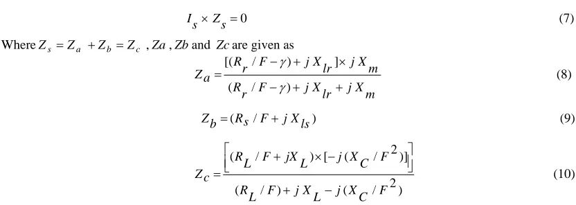
WhereZs Za Zb Zc ,Za,Zband Zcare given as
m X j lr X j F r R m X j lr X j F r R a Z ) / ( ] ) / [( (8) ) /
(Rs F jXls b
Z (9)
) 2 / ( ) / ( )] 2 / ( [ ) / ( F C X j L X j F L R F C X j L jX F L R c Z
(10)
In steady state, condition the self-excitationIa 0. Therefore, Zs must independently zero. This leads to the
following non-linear simultaneous equations with Xmand F as the unknown variables:
8 7 ) 6 5 ( 2 ) 4 3 ( 3 ) 2 1 ( ) ,
(Xm F A Xm A F A Xm A F A Xm A F A Xm A
P (11)
9 ) 8 7 ( 2 ) 6 5 ( 3 ) 4 3 ( 4 ) 2 1 ( ) ,
(Xm F B Xm B F B Xm B F B Xm B F B Xm B F B
Q (12)
The solution of equations (11) and (12) yield the value ofV,Xm,Xc. Along with these values, the machine
v F in
P
(17)
L R r I q out
P 2 (18) 100
in P
out P g
(19)
Using the equations (13) – (19) the performance characteristics of the asynchronous generators can be calculated.
3.2. With Load Controller
Fig.7 depicted the electrical equivalent representation of load and dump load. This connected across the point
A and B in a Fig.6. Even the consumer load is absent the dump resistance can able to absorb the rated power generated by the generator. So the load resistance and dump resistance are varies linearly.
Fig.7 equivalent circuit representation of consumer load and dump load
Since the dump load is a d.c load , the resistance offered by this load can be modify, which is applicable to a.c circuit by
ac R K dc
R (20) Where, k is the constant varies from 1.1 to 1.6,Racis the resistance offered by the ac circuit equivalent of Rdc. The performance characteristics of SEASG with the load controller could express by the equations [13]-[19] with modification of the effective resistance offered by the load and dump load. Only the difference is the magnitude of the load current.
4. SIMULATION
Fig.8 Simulation circuit of the proposed system
A control circuit of chopper has been developed diodes (D7 – D10), output of the diode rectifier is feeding to the summer circuit. Error and ramp signals are comparing, thereon the cross over pint detected by the Hit block in Mat Lab/Simulink. The output of the hit block is a pulse, which is to turn ON and turn OFF the IGBT switch. Therefore, power absorbed by the dump load controlled.
5. RESULT AND DISCUSSION
Fig.9 illustrates the generator terminal voltage and load current variation. Fig.10 and Fig (11) illustrates the simulation results of the study system with load controller. In Fig 9(a) and 9(b) the voltage and current transients are presents. However, in Fig10 (a) and Fig10 (b) such transients are absent. Nevertheless, the voltage magnitude is lees in Fig.9 (a) than in Fig 9(a). It is true because the load balancer act as an additional load of the generator. Thereon the load controller has to be retaining the terminal by change the effective impedance value at the point of common coupling.
Fig. 10 simulation results (a) voltage waveform (b) current waveform (c) both voltage and current waveform across the dump load
In Fig10 (a), the magnitude of the generated voltage is almost zero between the time intervals of 0 second and 2 seconds. Thereafter, the resistive load 98 Ω (Load-A) and another load (Load-B) of 98 Ω is adding to the generator terminals at 2 seconds and 5 seconds respectively. Thereupon the variation in voltage and current is illustrates in Fig 10(a) and Fig10 (b) respectively. In fig.10(c) illustrates the voltage and current variation across the dump load. Therefore, the power consumed by the load balancer also changed.
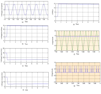
Fig. 11 Simulation results of control circuit (a) sampled voltage waveform (b) rectifier voltage (c) capacitor voltage (d) sampled voltage at sampling resistance (e) error voltage (f) comparing error and ramp pulse signal (e) triggering pulses
6. CONCLUSION
Simulation based performance study of a 3-Ø SEASG working as a stand-alone generator completed by using the Mat lab /Simulink software environment, Voltage regulation of the generator also completed by using load-balancing technique of d.c chopper circuit. The basic of the load load-balancing technique has reviewed by using the fundamental concept of d.c chopper circuit. Thereon this study concludes the control technique is a simple, easy to control and able to store the duped power in an energy storing devices like battery, capacitor etc…, Instead of wasting the power in the dup load it can recycle for electric utility like a heater.
ACKNOWLEDGMENTS
The authors acknowledge the management of Vellore Institute of Technology University, Vellore, India, 632014 for their support and keen interest in promoting the research and development in the power electronics division by providing all the required facilities and resources.
REFERENCES
[1] Basset E. D and Potter F. M. (1935), “Capacitive Excitation For Induction Generators,” AIEEE committee of Electrical Engineering, pp 535 - 545
[2] C. F. Wanger(1939), “Self-Excitation Of Induction Motors,” AIEE Trans., Vol. 58, pp. 47–51.
[3] E. Barkle and R.W. Ferguson (1954), “Induction Generator Theory And Application,” AIEE Trans., pt. III A, Vol. 73, pp. 12–19. [4] Novotny D.W.,Gritter and Studtman(1977), “Self-Excitation In Inverter Driven Induction Machines”, IEEE Transaction on power
[13]S.M. Alghuwainem(1999),“Steady-State Analysis Of An Isolated Self-Excited Induction Generator Driven By Regulated And Unregulated Turbines,”IEEE Trans. Energy Convers., 14, (3), pp. 718–723.
[14]T.F. Chen(1996), “Self-Excited Induction Generator Driven By Regulated And Unregulated Turbines’, IEEE Trans. Energy Convers,”Vol. 11, (2), pp. 338–343.
[15]A.K. Al – JabrI and A.I.Alolah (1935), “Capacitance Requirement For Isolated Self-Excited Induction Generator,” IEE Proc. B, 1990, 137, (3), pp. 154–159of a short-shunt induction generator Capacitive Excitation For Induction Generators,” AIEEE committee of Electrical Engineering, , pp 535 – 545.
[16]Murthy S. S, Singh, Nagamani C and Sathyanarayana(1988), “Studies On The Use Of Conventional Induction Motor As Self-Excited Induction Generators,” IEEE Transaction on energy conversion, Vol. 3, No. 4, , pp 842 – 848.
[17]Malik N. H., Al-Bahrani, A.H(1990)., Influence of the terminal capacitor on the performance characteristics of a self- excited induction generator,” IEE Proc., Vol.137, pt. C, No.2, pp 168-173.
[18]S.P.Singh., B. Singh, and M.P Jain(1990), ‘Performance characteristics and optimal utilization of a cage machine as capacitor excited induction generator’, IEEE Trans. Energy Convers., , 5, (4), pp. 679–685.
[19]Yogesh K. Chauhan, Sanjay K. Jain, and Bhim Singh (2010), “A Prospective on Voltage Regulation of Self-Excited Induction Generators for Industry Applications,” IEEE Transactions On Industry Applications, Vol. 46, No.2, pp 720 – 730.
[20]K. Subramanian , K.K.Ray, K. Hari Prasad, Nand Gopal,E., Nimisha Gupta, Nirupama,V., Pragya jha and Meenashi Singha (2010), “State Of The Art of Electronic Load Controller of Self- Excited Asynchronous Generator Used In Mini / Micro Hydro Power Generation”, ACEEE International Journal on Control System and Instrumentation, Vol. 1, No. 1, pp. 21-25.
[21]S. S. Murthy, Rini jose and Bhim Singh, “A practical load controller for stand alone small hydro system using Self- Excited Induction Generator”, IEEE Proceeding 1998 pp 359 – 364.
[22]S. S. Murthy, Bhim Singh, Ashish Kulkarni, R. Sivarajan and Sushma Gupta,“Field Eperiences on A Novel Pico – Hydel System using Self-Excited Induction Generator and Electronic load controller” IEEE proceeding, pp 842 – 847.
[23]Bhim Singh, S. S. Murthy and Sushma Gupta, “Analysis and Design of Electronic Load Controller for Self-Excited Induction Generators” IEEE Transactions on Energy Conversion, Vol. 21, No. 1, March 2006, pp 285 – 293.
[24]Bhim Singh, S. S. Murthy and Sushma Gupta, “Transient Analysis of Self-Excited Induction Generator with Electronic Load Controller ELC) Supplying Static and Dynamic Loads”, IEEE Transactions on Industry Applications, Vol. 41, No. 5, September/October 2005
[25]Bhim Singh, S. S. Murthy and Sushma Gupta, “An Improved Electronic Load Controller for Self-Excited Induction Generator in Micro-Hydel Applications”, IEE proceeding 2003, pp 2741 -2746.