R E S E A R C H
Open Access
SNR walls in eigenvalue-based spectrum
sensing
Andreas Bollig
*, Constantin Disch, Martijn Arts and Rudolf Mathar
Abstract
Various spectrum sensing approaches have been shown to suffer from a so-called signal-to-noise ratio (SNR)-wall, an SNR value below which a detector cannot perform robustly no matter how many observations are used. Up to now, the eigenvalue-based maximum-minimum-eigenvalue (MME) detector has been a notable exception. For instance, the model uncertainty of imperfect knowledge of the receiver noise power, which is known to be responsible for the energy detector’s fundamental limits, does not adversely affect the maximum-minimum-eigenvalue (MME) detector’s performance. While additive white Gaussian noise (AWGN) is a standard assumption in wireless communications, it is not a reasonable one for the maximum-minimum-eigenvalue (MME) detector. In fact, in this work, we prove that uncertainty in the amount of noise coloring does lead to an SNR wall for the maximum-minimum-eigenvalue (MME) detector. We derive a lower bound on this SNR wall and evaluate it for example scenarios. The findings are supported by numerical simulations.
Keywords: Spectrum sensing, Eigenvalue-based, SNR wall
1 Introduction
The recent years have seen an ever-growing demand for wireless spectrum not least due to the rise of the smart-phone in consumer markets. However, as a result of the licensing policies of the preceding decades, most of the radio spectrum can only be used by fixed licensees, many of which only make use of their spectral bands at cer-tain places or times. To alleviate the need for spectrum and make better use of the given resources, opportunistic spectrum access (OSA) [1] has emerged as a sub-field of cognitive radio. In opportunistic spectrum access (OSA), a spectral band can be used by unlicensed transceivers, so-called secondary users (SUs), if they are certain that the licensee of the band, the so-called primary user (PU), is not using it.
To make sure the occupancy status of a band is reli-ably detected, the SUsensesthe spectrum before using it. The goal of spectrum sensing is to decide between two hypotheses, the first of which states that the band of inter-est is free (H0), such that the SU can make use of it. The second hypothesis states that the band is occupied
*Correspondence: [email protected]
Institute for Theoretical Information Technology, RWTH Aachen University, Kopernikusstraße 16, 52074 Aachen, Germany
(H1), in which case the SU should refrain from accessing the band. The requirements spectrum sensing algorithms have to meet are quite demanding, e.g., the IEEE 802.22 standard for cognitive wireless regional area networks [2] states that an SU receiver should be able to reliably detect a primary user (PU) signal at a signal-to-noise ratio (SNR) of−22 dB. There are good reasons for these demanding requirements, like, e.g., the hidden terminal problem ([3] Ch. 14.3.3).
A number of spectrum sensing algorithms have been proposed in the literature [4–6]. Under the ergodicity assumption, these algorithms are typically able to meet the above requirement, i.e., if enough samples are avail-able, the probability density functions (PDFs) of the test statistics are well separable. However, due tomodel uncertainties caused by, e.g., colored or non-stationary background noise, non-ideal filters and imperfectly esti-mated parameters, detection algorithms can exhibit so-called SNR walls, i.e., SNR values, below which the detectors cannot robustly [7] decide between H0 and
H1. The existence of SNR walls has been established for the energy detector, the matched filter detector, and the cyclostationarity detector [8–10]. A spectrum sensing algorithm that, to the best of our knowledge, has not been linked to the signal-to-noise ratio (SNR)-wall problem
is the popular eigenvalue-based maximum-minimum-eigenvalue (MME) detector.
The contributions of this paper are manifold. We identify noise coloring as a model uncertainty adversely affecting the maximum-minimum-eigenvalue (MME) detector. Then, we show that uncertainty in the amount of noise coloring leads to an signal-to-noise ratio (SNR)-wall for the maximum-minimum-eigenvalue (MME) detector by using noise coloring to derive a lower bound on the signal-to-noise ratio (SNR)-wall of the
maximum-minimum-eigenvalue (MME) detector. Finally, we
support the analytical results with numerical simulations. The rest of the paper is structured as follows. In Section 2, we introduce our signal model alongside the test statistic of the maximum-minimum-eigenvalue (MME) detector. Section 3 formally defines the term signal-to-noise ratio (SNR)-wall, while Section 4 explains why colored noise is a reasonable assumption in wire-less communication. In Section 5, a lower bound on the signal-to-noise ratio (SNR)-wall for the
maximum-minimum-eigenvalue (MME) detector is derived.
Example scenarios with concrete values for the lower bound from Section 5 are given in Section 6. A numerical evaluation of our results can be found in Section 7, while Section 8 concludes the work.
2 Signal model and MME test statistic
Consider the discrete time complex baseband signalx(n) observed at a secondary system receiver, wherendenotes the discrete time index. The task of a spectrum sens-ing algorithm is to decide between the followsens-ing two hypotheses
H0:x(n)=η(n)
H1:x(n)=s(n)+η(n),
(1)
where s(n)represents a primary user (PU) signal, while η(n)stands for additive noise. For the sake of simplicity, no channel fading effects are taken into account.
Throughout this work, the primary user (PU) is assumed to transmit a linearly modulated signal with sym-bol length Tsymbol exhibiting a rectangular pulse shape. The signal is oversampled at the receiver with an integer oversampling rate given by M = Tsymbol
Tsample, where Tsample denotes the sampling period. The decision whether the band under observation is free (H0) or occupied (H1) is based on a block ofN samples. In the decision process, samples from p different receivers are considered. The samples available at the fusion center at time instantnare given by
x(n)=x1(n),x1(n−1),. . .,x1(n−Q),
x2(n),. . .,xp(n),. . .,xp(n−Q) T
, (2)
where the subscript indicates which receiver the samples are from. Each receiver contributes a consecutive set of Q+1 samples, where the quantityQ+1 is the so-called smoothing factor [11]. The inclusion of samples from dif-ferent receivers as well as samples from difdif-ferent points in time allows the maximum-minimum-eigenvalue (MME) detector to exploit correlation from both domains in the detection process. For simplicity, all receivers are assumed to experience the same signal-to-noise ratio (SNR). The vectorss(n)andη(n)are defined analogous tox(n), lead-ing to the concise representation
x(n)=s(n)+η(n). (3)
We consider a scenario with a single primary user (PU) transmitter and multiple SU receivers. The receivers are assumed to be perfectly synchronized, i.e., si(n)|pi=1 =
s(n). Signal and noise are generated by mutually inde-pendent stationary random processes. The primary user (PU) signal s(n) is zero-mean, has variance σs2, and its symbols are independent, i.e.,s(n)ands(n+M)are inde-pendent and identically distributed (i.i.d.). The receiver noiseηi(n)is zero-mean and has varianceση2for alli. The noise vectorη(n) is distributed according to a circularly symmetric complex Gaussian distribution, i.e., η(n) ∼ CNp(Q+1)(0,Rη).
Considering the fact that both the signal and the noise are zero-mean, the statistical covariance matrices can be obtained as
Rs=E
s(n)s(n)H
Rη=Eη(n)η(n)H Rx=E
x(n)x(n)H =Rs+Rη,
(4)
where(·)Hdenotes the complex conjugate transpose. We assume that the received signalx(n)is covariance ergodic ([12], pp. 531), such that the sample covariance matrix
ˆ Rx(N)=
1 N−Q
N−1
n=Q
x(n)x(n)H (5)
asymptotically converges to the statistical covariance matrix, i.e.,
lim
N→∞Rˆx(N)=Rx. (6)
The analytic derivations in this work target the well-known maximum-minimum-eigenvalue (MME) detector [11]. Its test statistic is composed of the eigenvalues of the received signal’s sample covariance matrix. The test statistic and its accompanying decision rule are given by
MME(x,N)= λmax
ˆ Rx(N)
λmin
ˆ Rx(N)
H≶0
H1
where λmax(·) andλmin(·)denote the largest and small-est eigenvalue of a matrix respectively and γ stands for the predefined decision threshold. If MME(x,N) < γ, we decideH0, while forMME(x,N) ≥ γ, we decideH1. Since both sample and statistical covariance matrices are positive-semidefinite and thus all of their eigenvalues are ≥0, the test statisticMME(x,N)is always≥1.
3 SNR walls in spectrum sensing
Additive white Gaussian noise (AWGN) is a standard assumption in wireless communications research and for many problems in the field, it is a reasonable one. Indeed, a classical result from information theory states that additive Gaussian noise represents the worst case in point-to-point communication [13], which makes it a fair choice for performance evaluation. However, model-ing the receiver noise as additive white Gaussian noise (AWGN) is only an approximation of reality and for eigenvalue-based spectrum sensing, where correlation in the received signal is the key to differentiability between the H0and the H1 case, it does not embody the worst case. As will be shown in the subsequent sections, the assumption that the (Gaussian) noise samples are i.i.d. (and thus the noise iswhite) is a crucial prerequisite for the maximum-minimum-eigenvalue (MME) detector’s opti-mal operation. To take into consideration that different types of noise exist, we modelη(n)as having any distri-bution W from a set of possible distributions W, all of which have the variance ση2. The maximum-minimum-eigenvalue (MME) detector is a general spectrum sensing algorithm in the sense that it is capable of detecting dif-ferent kinds of signals. Thus, we do not assume a fixed signal type but instead only make the assumption that the primary user (PU) signals(n)has any distributionSfrom the set of possible distributionsS, all of which have the varianceσs2.
Given the setsS andWwith the variancesσs2andση2 respectively, we can now define the signal-to-noise ratio (SNR) as
SNR= σ
2
s
σ2
η. (8)
Further, we define the probability of false alarm and the probability of missed detection as
Pfa(W,N)=P(MME(x,N)≥γ |H0,W), Pmd(W,S,N)=P(MME(x,N) < γ |H1,W,S),
(9)
respectively. In conformity with the definition in [9] (except that we do not consider a fading channel), we let a detectorrobustlyachieve a pair (Pfa,Pmd) consisting of
a target false alarm probability Pfa and a target missed detection probabilityPmdif it satisfies
sup
W∈WPfa(W,N)≤Pfa, sup
W∈W,S∈SPmd(W,S,N)≤Pmd.
(10)
The detector is called non-robust at a given SNR if at that SNR even with an arbitrarily highN, it cannot achieve any pair (Pfa,Pmd) on the supportPfa ∈[ 0, 0.5] ,Pmd ∈ [ 0, 0.5]. The SNR wall is finally defined as
SNRwall=sup{SNRt, s.t. the detector is non-robust
for all SNR<SNRt}.
(11)
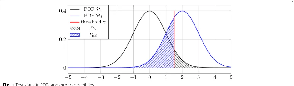
For test statistics with symmetric probability density functions (PDFs), a definition of non-robustness equiv-alent to the above is that a detector is non-robust if the sets of means of the test statistic(x,N) under the two hypotheses overlap [9]. This equivalence can be eas-ily illustrated using Fig. 1. As can be seen, changing the threshold leads to a different pair (Pfa,Pmd). The set of achievable pairs (Pfa,Pmd) depends on the shape and the location of the test statistic probability density func-tions (PDFs). For symmetric probability density funcfunc-tions (PDFs), e.g., the ones illustrated in Fig. 1, achieving a pair (Pfa,Pmd) on the supportPfa ∈[ 0, 0.5] ,Pmd ∈[ 0, 0.5], i.e., being robust, means that the threshold cannot be above the mean of theH1PDF because this would result in a Pmd > 0.5. Analogously, the threshold cannot be below the mean of theH0PDF because thenPfa >0.5. Thus, if the sets of means overlap, i.e., if there is aH1mean that is below one of theH0means, no matter what value is cho-sen for the threshold, either Pmd or Pfa is always> 0.5 such that the detector is non-robust.
Since the H0 andH1 test statistic probability density functions (PDFs) of the maximum-minimum-eigenvalue (MME) detector are not symmetric, we use a third def-inition of non-robustness, which states that a detector is non-robust if the sets of medians of the test statistic (x,N)under the two hypotheses overlap. This definition is equivalent to the first one, even for non-symmetric dis-tributions. For symmetric distributions, it coincides with the second definition. The reason we need to use the median instead of the mean is that for non-symmetric dis-tributions, it does not hold that the probability above the mean as well as the probability below the mean is 0.5, while the same does by definition hold for the median.
Fig. 1Test statistic PDFs and error probabilities
4 Sources of noise and noise coloring
As mentioned in Section 3, additive white Gaussian noise (AWGN) can only be considered an approximation of the actual noise experienced at a radio receiver. In this section, we make the case for considering colored receiver noise, which is an assumption used in the subsequent sections to prove the existence of an SNR wall for the maximum-minimum-eigenvalue (MME) detector.
In [11], it is assumed that the receiver noise before pro-cessing is white and that the only source of noise coloring is the use of a receive filter. The receive filter is assumed to be known in advance and to be invertible, such that a pre-whitening filter can be used to re-whiten the received samples before including them in the computation of the test statistic. On close inspection, it seems to be prob-lematic to remove all coloring, since perfect filter design is hardly achievable, which makes employing an exact inverse of the receive filter seem impossible.
Even if the coloring caused by the receiver architecture was perfectly reversible, the assumption that the exter-nal noise is white represents an oversimplification, which in the case of the maximum-minimum-eigenvalue (MME) detector happens to be inappropriate, since for this detec-tor uncorrelated noise is a requirement for proper func-tioning. In reality, the external noise is a superposition of different kinds of noise from various sources and although the impact of external noise decreases for higher fre-quencies [14], at moderate frefre-quencies such as the ones used for television broadcasting, external noise is present and should be considered. Note that the television bands are of utmost interest for spectrum sensing, i.e., many spectrum sensing algorithms originated in the context of the IEEE 802.22 standard [2], which is concerned with communication in vacant television bands.
There are multiple different sources of realistic non-white external noise. One example is galactic radiation noise. The power spectral density (PSD) of such noise is proportional to f12.7 [15], wheref denotes the frequency, which makes it non-white. Another example is man-made
noise [16]. The reason this kind of noise leads to correla-tion in the received samples underH0is twofold. Firstly, it occurs in strong bursts that affect multiple receiver samples, which leads to time correlation. Secondly, when multiple receivers or multiple receive antennas are con-sidered, the received noise is correlated in the case that multiple of them are in the range of the same man-made impulsive noise. The origin of man-made noise lies in, e.g., unintended radiation from electrical machinery or power transmission lines. Furthermore, nearly every electronic device creates it and thus, impulsive man-made noise is an effect that needs to be taken into account.
As pointed out above, expecting receiver noise to be white and uncorrelated is unrealistic due to imperfect filters, galactic radiation noise, and different sources of man-made noise. Thus, in the remainder, we investi-gate what effect non-white noise has on the perfor-mance of the maximum-minimum-eigenvalue (MME) detector.
5 SNR wall lower bound
In this section, we derive a lower bound on the SNR wall of the maximum-minimum-eigenvalue (MME) detector, thus proving its existence. More specifically, following the definition of the SNR wall from Section 3, we derive a lower bound on the SNR value below which the sets of medians of the test statistic (x,N) under the two hypotheses (H0andH1) overlap even in the asymptotic case (N → ∞). To determine the location of the over-lap, we provide a lower bound on the test statistic under
In our system model, the matrices Rs andRη are no
Toeplitz matrices. The reason can be found in the com-position of the vector x(n), i.e., the covariance matrices contain two types of correlation, time, and receiver corre-lation (cf. (2)). Note, that this is the case despite the facts that firstly, due to our asymptotic approach, the matri-ces are statistical covariance matrimatri-ces and secondly, the underlying noise processes are assumed to be stationary. The correlation coefficients associated with the entry in thei-th row andj-th column ofRsandRηare denoted by
ρs ijandρ
η
ij, respectively. Bounds will be denoted by a bar
above the respective symbol.
5.1 Lower bound on the test statistic underH0
In the H0 case, Rx = Rη, since no primary user (PU)
signal exists. For this case, we aim at finding alowerbound ¯
asym, lo
MME,H0on the asymptotic test statistic, i.e., ¯ determine a lower bound on the largest eigenvalue (λ¯lomax(Rη)) and an upper bound on the smallest eigenvalue
According to the Courant-Fischer theorem, the
maximum and minimum eigenvalues λmax(H) and
λmin(H) of a Hermitian matrix H can be obtained by solving the following optimization problems [17]
λmax(H)= max
From (14), it directly follows that
λmin(H)≤zHHz≤λmax(H), (15)
for an arbitrary normalized z. This means that we can obtain the boundsλ¯lomaxRηandλ¯upminRηby simply eval-uating λ¯lomaxRη = zH1Rηz1 and λ¯upminRη = zH2Rηz2 using two arbitrary normalized vectorsz1 andz2. How-ever, an additional constraint we need to take care of when obtaining the bounds is thatλ¯lomaxRη≥ ¯λupmin
Rηneeds to hold. In the following, we construct a set of vectorsz1 andz2that guarantees that this property is satisfied.
Given a specific covariance matrixRη, the vectors are
constructed as to extract its largest correlation coefficient ρmaxη with ρmaxη ≥ ρijη ∀i,jwith i = j. For the below
example, we assume that the largest correlation coefficient
is located at thek-th column of the first row of the matrix. Given the Hermitian structure of covariance matrices and the assumed stationarity of the noise processes, this assumption can be made without loss of generality. The considered covariance matrix has the following structure
Rη=ση2
The accompanying vectorsz1andz2are given by
z1= √1 Note that the above argument can be made for an arbitrary position ofρmaxη by choosingz1andz2 accord-ingly, leaving (18) unchanged. Note also thatλ¯lomaxRη≥
¯ λup
min
Rη holds. The lower bound on the test statistic underH0is now given by
0, where the first inequality is due to the general pos-itive semidefiniteness of covariance matrices. Since for λmin
Rη = 0 detection becomes impossible (cf. (7)), we exclude the case of complete noise correlation.
5.2 Upper bound on the test statistic underH1
In theH1case, Rx = Rs+Rη. For this case, we aim at
finding anupperbound¯asym, upMME,H
¯ λup
max(Rx)
and a lower bound on the smallest eigenvalue
¯
column. Given our assumptions from Section 2, we get
rii=ση2+σs2=(1+SNR)ση2,
According to the Gershgorin circle theorem [18], all eigenvaluesλk|gk=1of a matrixA∈Cg×g, withg=p(Q+
1), lie within the union of the circular disks
{z∈C:|z−aii| ≤Ri}, (23)
Since Rxis Hermitian, all of its eigenvalues are real and
thus the disks from (23) become intervals on the real axis. The value ofriiis independent ofi. Thus, an upper bound
on the maximum eigenvalue of Rxcan be obtained as
¯
In analogy to (25), a lower bound on the minimum eigenvalue of Rxcan be obtained as
¯
However, for (26) to be a valid bound in terms of the test statistic, we need to introduce an extra constraint. We
need to make sure thatλ¯lomin(Rx) >0, i.e.,|rii| −max i Ri>
0, which leads to the constraint
1+SNR>max
Combining (25) and (26) finally provides the upper bound on the asymptotic test statistic underH1given by
¯
5.3 Lower bound on the SNR wall
Combining (19) and (28), we can say that the maximum-minimum-eigenvalue (MME) detector is non-robust under the condition given by (27) and given thatρmaxη <1 when¯MME,asym, upH
Note that the correlation coefficients in theH0case are now denoted by instead ofρ to facilitate the distinc-tion between the noise correladistinc-tion in theH0and theH1 case. For the interpretation of (29), it is important to note thatρijs ≥ 0 ∀ i,j, i.e., the signal correlation coefficients never become negative. This follows from (2), (4), and the assumption that consecutive symbols are independent.
6 Examples of the lower bound on the SNR wall
Inequality (29) is quite involved and does not allow for easy interpretation. Since our goal is to prove the exis-tence of an signal-to-noise ratio (SNR) wall, we continue our investigation with examples that simplify (29), facili-tating interpretation. We consider the case, where under
different locations. Considering uncorrelated noise under
H1, (27) can be simplified as follows
1+SNR>max
This means that the higher the correlation in the sig-nal samples, the lower the sigsig-nal-to-noise ratio (SNR) for which our lower bound is defined. Forκmax <1, the con-dition is never satisfied. In this case, we have to fall back to zero as a lower bound forλmin, which is guaranteed by the properties of covariance matrices. This however leads to the test statistic underH0taking the value infinity, which again rules out the possibility of giving a lower bound for an signal-to-noise ratio (SNR) wall. For a more concise notation, let
αmax= ¯MME,asym, loH0 =
1+ ηmax 1− ηmax
. (32)
By assuming a minimal amount of noise coloring under
H0and excluding the case of complete noise correlation, we restricted the support of the largest noise correlation coefficient, such that max ∈ (0, 1). As a consequence, it holds thatαmax > 1. Using the definitions ofκmax and αmax, as well as the assumption that underH1the noise is uncorrelated, (29) becomes
In order to obtain concrete numbers for the bound, we will look at more specific examples in the following.
6.1 Receiver correlation (Q=0,p≥2)
In this example, we consider ap-receiver setup with per-fect signal correlation, i.e.,ρijs = 1 ∀ i,j. The maximum signal correlation in this case isκmax = p−1 and thus the condition (30) becomes SNR< p−21 . If the condition
is satisfied, we can say that the maximum-minimum-eigenvalue (MME) detector becomes non-robust for
SNR≤ αmax−1
p+αmax(p−2)
. (35)
Forp= 2 and a maximum noise correlation of maxη = 0.05, which we consider to be moderate noise coloring,
we arrive at a lower bound of SNR = 0.052632 =
−12.788 dB, which is considerably far away from−22 dB (cf. Section 1). This example is simple enough for us to obtain the actual statistical covariance matrices for an evaluation of the bound’s tightness. They are given by
RH0
With the above covariance matrices, the asymptotic test statistics evaluate toHasym0 = 1.10503 andasymH1 = 1+ 2SNR. This means that for an signal-to-noise ratio (SNR) below 0.052632= −12.788 dB,Hasym1 < asymH0 , such that the detector becomes non-robust, i.e., in this special case the bound is tight.
6.2 Time correlation (p=1,Q≥1)
To complement the receiver correlation example, we next investigate a case with only one receiver that examines the correlation of the received samples over time. In order to again obtain a bound via (34), the value ofκmaxneeds to be determined. Given an oversampling factorMand the independence of consecutive symbols, the autocorrelation function of the primary user (PU) signal can be obtained as
In our case, the row with the maximum off-diagonal cor-relation sum inRsis the
g+1
2
-th one, whereg=Q+1 is the number of rows ofRsand·denotes the floor
opera-tion. This is illustrated in the following example forQ=3
(assumingM≥3)
In order to obtain κmax, three cases have to be distin-guished. For
Q
2
<MandQeven, we get
κmax=2
Q
2
j=1
1− j
M
=Q−Q
2+2Q
4M ,
(39)
for
Q
2
<MandQodd, we get
κmax=2
Q−1 2
j=1
1− j
M
+
1− Q+1
2M
=Q−(Q+1) 2
4M ,
(40)
and forQ2≥M, we get
κmax=2
M−1
j=1
1− j
M
=M−1, (41)
where·denotes the ceiling operation. In this example, we model the noise as a stationary auto-regressive pro-cess of order one (AR(1)). It is supposed to mimic white external noise that has undergone filtering by a low-pass receive filter. The noise process is given by
η(n)=0.1η(n−1)+(n), (42)
where (n) denotes an i.i.d. complex Gaussian random process with mean zero and variance 0.99. It is indepen-dent ofη(n−1)and has independent real and imaginary parts and E|η[n]|2 = 1. Figure 2 shows the noise process’s power spectral density (PSD) to illustrate its
Fig. 2PSD of AR(1) process, which followsη[n]=0.1η[n−1]+[n]. The frequency is normalized tofsamples=2π
characteristics. We consider the case ofQ=3 andM=4, where the choice ofQleads to the noise covariance matrix
Rη=
⎛ ⎜ ⎜ ⎝
1 0.1 0.12 0.13
0.1 1 0.1 0.12
0.12 0.1 1 0.1
0.13 0.12 0.1 1
⎞ ⎟ ⎟
⎠ (43)
and κmax = 2 (cf. (40)). Using (34), we again get a lower bound for the signal-to-noise ratio (SNR)-wall of −12.788 dB.
6.3 Time and receiver correlation (p>1,Q>0)
As a final example, we consider the case where both, time and receiver correlation, are exploited. Given our model assumption that the signal strength is equal for all receivers, we can combine theκmax terms derived in the preceding subsections to obtain
κmax=p−1+p·κmax,time, (44)
whereκmax,timedenotes theκmaxterm for time correlation.
7 Numerical evaluation
In this section, we provide numerical results correspond-ing to the examples given in Section 6.1 and Section 6.2. The parameters used in the simulations can be found in Table 1.
For theH1case, we generate white Gaussian noise and an oversampled binary phase shift keying (BPSK) sig-nal with a rectangular pulse shape and symbols that are independent of each other. For the H0 case, we gen-erate colored noise. The different noise types used for
H0andH1 represent the model uncertainty that has to be taken into account when designing spectrum sensing algorithms. When generating colored noise, our aim is to create a stationary, sampled Gaussian process with a predefined covariance matrix.
7.1 Receiver correlation
In the receiver correlation case, we use a matrix multipli-cation approach for generating colored noise. We start by generating thep-dimensional white Gaussian noise sam-ple vector w(n) ∼ N(0,Rw) for all time instances n,
where Rw = Ip×p, while p is the number of receivers.
That is, the vector w(n) is generated according to a
Table 1System parameters
Parameter Symbol Value(s)
Modulation type BPSK
Oversampling factor M 4
Number of samples N {999, 9999, 999999} No. of Monte Carlo instances 2000
p-dimensional zero-mean Gaussian distribution with the identity matrix as its covariance matrix. The colored noise vector η(n), which is experienced at the receiver in the
H0 case, is subsequently obtained as η(n) = Aw(n), where the matrixA∈Cp×pneeds to be chosen such that the covariance matrix of η(n) equals the predefinedRη. This approach leads to the desired result due to the fact that linear combinations of Gaussian random variables are again distributed according to a Gaussian distribu-tion. It is well known that the covariance matrix ofAw(n) is given by AHRwA. Thus, the matrix A can be
eas-ily obtained by computing the Cholesky decomposition Rη=AHA.
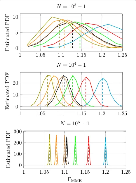
Figure 3 shows the histograms for the
maximum-minimum-eigenvalue (MME) test statistic MME in the
H0 case (black) and the H1 case (colored). For the H1 case, the test statistic histograms for different SNRs are shown. It can be observed that the estimation variance of the test statistic decreases with an increasing number of samplesN, which is to be expected since asymptotically
Fig. 3Estimated probability density function for receiver correlation (p=2,Q=0) and differentN. Noise correlation factor maxη =0.05. Solid linesrepresent the histograms, whiledashed linesdepict the means. TheH0case result is shown inblack, while theH1case results arecolored, where the SNR from right to left is given by {−10,−11,. . .,−15}dB
the sample covariance matrix converges to the statistical covariance matrix. What we can also see is that the mean of the estimated test statistic changes for an increasing N. This is a testimony to the biasedness of the estimator (7). Recall, that the lower bound on the signal-to-noise ratio (SNR) wall for this scenario has been derived to be −12.788 dB. The simulation results confirm this bound. Indeed, when the signal-to-noise ratio (SNR) drops below the derived bound, the medians of the test statistics under
H1are below the median of the test statistic under H0 for all inspectedN, making the detector non-robust by definition.
7.2 Time correlation
Since in the previous example, the noise correlation only exists between the noise processes of different receivers but not between noise samples taken at a single receiver at different times, the matrixA, which is used to color the noise, has a small dimension. This makes the matrix multiplication approach feasible for the receiver corre-lation example. To use the same method in the time correlation example, a coloring matrix of size N × N would be necessary, where in our simulations, N takes on values of up to 106. This renders the matrix mul-tiplication approach infeasible for the current example. Thus, a different approach for generating colored noise has to be taken. First, we generate an autocorrelation with a real-valued power spectral density (PSD) from an autoregressive model of order one. We then gener-ate anN-dimensional vector distributed according to a zero-mean, unit-variance, complex, white Gaussian distri-bution, which serves as a frequency-domain noise basis. Its power spectral density (PSD) is subsequently scaled by the power spectral density (PSD) of the autocorrelation, after which it is transformed to the time-domain via the inverse discrete Fourier transform (IDFT) and scaled to varianceση2. Here again, we use the fact that a linear com-bination of Gaussian random variables is also distributed according to a Gaussian distribution.
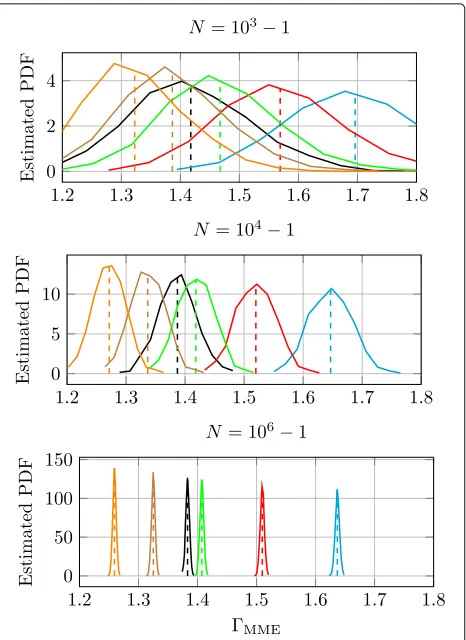
Recall that the lower bound on the signal-to-noise ratio (SNR) wall for this scenario has been derived to be −12.788 dB. According to the numerical results, in this scenario, the maximum-minimum-eigenvalue (MME) detector exhibits an signal-to-noise ratio (SNR) wall between−8 and−9 dB (Fig. 4). While the lower bound cannot be called very tight for this example, it neverthe-less proves the existence of an signal-to-noise ratio (SNR) wall, which is guaranteed to be much higher than the desired−22 dB.
8 Conclusions
Fig. 4Estimated probability density function for time correlation (p=1,Q=4) and differentN.Solid linesrepresent the histograms, whiledashed linesdepict the means. TheH0case result is shown in black, while theH1case results arecolored, where the SNR from right to left is given by{−6,−7,. . .,−10}dB.
sensing algorithm. The signal-to-noise ratio (SNR) wall is caused by uncertainty about the coloring of the receiver noise. A lower bound on the signal-to-noise ratio (SNR) wall is derived and is complemented by time and receiver correlation examples. For the example, we give con-crete signal-to-noise ratio (SNR) values, below which the maximum-minimum-eigenvalue (MME) detector is non-robust. Finally, numerical results supporting the analytical results are provided.
One possible direction for future work is the derivation of tighter bounds on the signal-to-noise ratio (SNR) wall. Also, it would be of great value if the results could be gen-eralized to arbitrary eigenvalue-based spectrum sensing algorithms.
Funding
This work was partly supported by the Deutsche Forschungsgemeinschaft (DFG) project CoCoSa (grant MA 1184/26-1).
Competing interests
The authors declare that they have no competing interests.
Publisher’s Note
Springer Nature remains neutral with regard to jurisdictional claims in published maps and institutional affiliations.
Received: 12 October 2016 Accepted: 6 June 2017
References
1. Q Zhao, BM Sadler, A survey of dynamic spectrum access. IEEE Signal Proc. Mag.24(3), 79–89 (2007)
2. IEEE, IEEE Standard for Information Technlogy-Telecommunications and information exchange between systems; Wireless Regional Area Networks (WRAN)-Specific requirements Part 22: Cognitive Wireless RAN Medium Access Control (MAC) and Physical Layer (PHY) Specifications: Policies and Procedures for Operation in the TV Bands. IEEE Std 802.22-2011 (2011). https://www.ieee.org/documents/ieeecitationref.pdf 3. A Goldsmith,Wireless communications. (Cambridge University Press,
Cambridge, 2005)
4. E Axell, G Leus, EG Larsson, HV Poor, Spectrum sensing for cognitive radio: state-of-the-art and recent advances. IEEE Signal Proc. Mag.29(3), 101–116 (2012)
5. T Yücek, H Arslan, A survey of spectrum sensing algorithms for cognitive radio applications. IEEE Commun. Surv. Tutorials.11(1), 116–130 (2009) 6. Y Zeng, Y-C Liang, AT Hoang, R Zhang, A review on spectrum sensing for
cognitive radio: challenges and solutions. EURASIP J. Adv. Signal Process.
2010(2010). https://link.springer.com/article/10.1155/2010/381465 7. PJ Huber,Robust statistics. (Springer, Berlin, 2011)
8. A Sonnenschein, PM Fishman, Radiometric detection of spread-spectrum signals in noise of uncertain power. IEEE Trans. Aerosp. Electron. Syst.
28(3), 654–660 (1992)
9. R Tandra, A Sahai, SNR walls for signal detection. IEEE J. Selected Topics Signal Process.2(1), 4–17 (2008)
10. R Tandra, A Sahai, inIEEE International Symposium on New Frontiers in Dynamic Spectrum Access Networks (DySPAN). SNR Walls for Feature Detectors, (2007), pp. 559–570
11. Y Zeng, Y-C Liang, Eigenvalue-based spectrum sensing algorithms for cognitive radio. IEEE Trans. Commun.57(6), 1784–1793 (2009)
12. A Papoulis, SU Pillai,Probability, random variables, and stochastic processes, 4th edn. (McGraw-Hill, New York City, 2002)
13. I Shomorony, AS Avestimehr, Worst-Case Additive Noise in Wireless Networks. IEEE Trans. Inf. Theory.59(6), 3833–3847 (2013)
14. International Telecommunication Union, Recommendation P.372-12: Radio noise. Technical report (2015). https://www.itu.int/rec/R-REC-P. 372/en. Accessed 23 Nov 2015
15. CD Motchenbacher, JA Connelly,Low noise electronic system design. (Wiley, Hoboken, 1993)
16. A Wagstaff, N Merricks, Man-made noise measurement programme (AY4119) - final Report. Technical Report Issue 2, Mass Consultants Limited (2003)
17. RM Gray,Toeplitz and circulant matrices: a review. (Now Publishers, Boston, Delft, 2006)
![Fig. 2 PSD of AR(1) process, which follows η[ n] = 0.1η[ n − 1] +ϵ[ n].The frequency is normalized to fsamples = 2π](https://thumb-us.123doks.com/thumbv2/123dok_us/929691.1112861/8.595.53.294.86.388/fig-psd-ar-process-follows-frequency-normalized-fsamples.webp)