DEVELOPMENT OF FLEX SENSOR
ARRAY TO IDENTIFY DAMAGE ON
SHEET METAL
ALAPATI SREEJANM. Tech. Scholar, Department of Mechanical Engineering, VNR VJIET,Hyderabad, 500049, India
YEOLE SHIVRAJ NARAYAN
Professor, Department of Mechanical, VNR VJIET, Hyderabad, 500049, India [email protected]
Abstract: Sheet metal is among the most widely used form of metal in metalworking industry. Among different applications, if the sheet metal is used on an automobile, locker or a strong room door, recording deformations due to impact will be a significant idea. Especially if a sensor system exists that can distinguish minor deformation from major deformation and also identify location of deformation on metal sheet can be useful for alert generation that is precise about the damage. To give sense to the sheet metal panels by attaching sensors is possible. The idea is to record the shape of the sheet itself, by attaching an array of flex sensors in two dimensions across the metal sheet. The metal sheet with sensors attached, can then be viewed as a finite number of cells which are about the size of the sensors that are attached. Over a larger area, the number of cells that show deformation tells us extent or proportion of sheet that is damaged and, location of damage on sheet from the location of sensor cells. A prototype is built, of this idea, from designing shape of sensor that suits the application to interfacing the sensors to microcontroller; along with a tool to visualize the damage on a computer is done.
Keywords: Automobile, Damage detection, Flex sensor, Flexure, Lockers, Sheet metal, Velostat. 1. Introduction
Flex sensor, also called bend sensor, measure the amount of deflection caused by bending the sensor. While several types of flex sensors exist, the commercial ones widely available are conductive ink coated flex sensors. Carbon particulate coatings are laid on a plastic substrate and electrodes measure the resistance along the length of the sensor. When sensor tends to bending, the distances between particles vary which will lead to increase in resistance when distance is more and vice versa [1].
Not all applications involving flex sensors require high amount of accuracy, and commercially available ones are not cheap. Cost effective flex sensors were earlier hand fabricated for applications where accuracy is not an issue, by using the innate property of a kind of plastic known by trade names Velostat or Linqstat. The hand fabricated flex sensors are popular among Arduino or any other microcontroller community. These cost effective sensors use Velostat or Linqstat plastic as sensing element, which are Polyolefins impregnated with carbon black. They are available as sheets with thickness of about 0.1 mm, and they are used for making Anti-Static bags to insulate electronics from external charges.
Upon flexing the plastic sheet, it displays a change in resistance, but measuring through the thickness of sheet rather than length unlike conductive ink flex sensors. So, a flex sensor can be made by sandwiching the plastic between conductive electrodes, and measuring resistance as they are flexed.
1.1.Applications of the sensor
Flex sensor has applications in many fields of study. When invented, they were used widely for rehabilitation research and Human Machine Interfaces, by incorporating them into goniometric gloves. Later, papers published show their application into geology to identify landslides and in tangible musical interfaces to encourage musical discovery, showing the increasing potential into various fields [2].
The interest in identifying damage by using instruments and sensor systems is not new. Damage was only recorded on aircrafts earlier, as a part of maintenance. Recently the interest has been put in identifying damage on automobiles, using piezo-electric vibration sensors or accelerometers [6] [7]. Both of which can identify collision, but cannot give precise data about location of impact or proportion of damage. Also, in case of using vibration sensors for damage detection, complex computer algorithms were written to identify major damage from minor damage [6]. This also increases the cost of sensor system.
It is a novel idea to record the data about change in shape of metal sheet, rather than using a sensor that responds to external impact as a damage detection system. Moreover, it can be used not just in automobiles, but also where sheet metal is used and that needs monitoring.
Telematics for automobiles has a wide variety of sensors that inform user about the condition of vehicle. This damage detection method can provide the conditional data of automotive sheet metal panels. Also this damage identification method can provide conditional data of sheet metal in applications like lockers.
Hence, this paper aims at creation of proof of concept of a damage detection sensor system on a prototype sheet metal.
2. Sensor
Damage on metal sheet can show up as dent, flexure or tear. However, as initial stage identifying damage, the work presented only talks about identifying flexure. The response of the sensor system to tear in metal sheet is not tested. Also, if the sensor is detached during damage, it can be assumed as damage at that location.
Flex sensors are usually thin strips that are designed to read flexure only in one dimension. However, the need arises here, that the sensor should be capable of measuring flexure in two dimensions across the surface of the sheet.
Fig. 1 Conductive ink type commercially available Flex Sensor
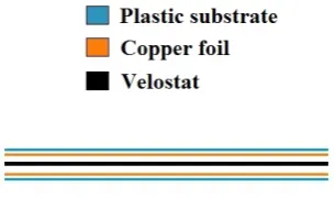
It is obvious to fabricate a custom sensor as commercial sensors needs to be arranged in two dimensions perpendicularly for this particular requirement, which would increase number of sensors used and it is not cost effective. Construction is done similar to above said method by sandwiching the Velostat between copper foil, only copper foil is stuck to a plastic substrate increase stiffness of sensor, along with Velostat and conductive layers. Copper foil is attached to plastic substrate to avoid copper foil layers to shift from position. But, Velostat needs to slide relatively to accommodate bending.
Fig. 2 shows the layered construction of the sensor. The copper foil and the plastic substrate are stuck together, and hence they are shown closer to each other than the Velostat layer. There may be a thin air gap between the copper foil and Velostat layer, but it will be displaced when sensor is flexed or bent.
The layers can be cut into any shape and size, until the copper foil is held in position by the construction shape and the Velostat is relatively moving. Once the layers are laid accordingly, they should be isolated from external disturbances, both mechanical and electrical. Mechanical disturbances such as the sliding of layers out of position when flexed should be avoided. Also if not isolated properly, copper foils may connect directly by external means and resistance through Velostat could not be measured. Thus, any external disturbances may deteriorate or halt the functionality of the sensor.
Fig. 2 Construction of Velosat Flex sensor
Although the construction of sensor need not be contemplated, as Velostat sensors are popular among the Arduino community. However, the initial trials of construction of sensor are also presented to clarify the selection of sensor to be in the form of hash (#).
substrate is stiff and side length is small, flexibility decreases and considerable amount of force is required to bend the sensor. This may not allow the sensor bend according to the deflection in sheet, and may result in improper readings.
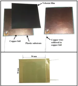
Fig. 3 Precursor square sensor
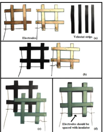
To make the sensor flexible the substrate should be thin and long. Four plastic strips of size 9 mm × 1 mm were cut as a part of a single electrode and arranged in hash as shown in Fig. 4a. Copper foil is cut in little lesser dimensions 8.5 mm × 0.8 mm, is stuck onto all four plastic substrate and soldered with copper wire together, to make it a single electrode as in Fig. 4a. Two such electrodes are prepared which should be sandwiched together
with Velostat in between. So a layer of Velostat cut into four strips with dimensions same as plastic substrate, larger than copper foil, to prevent direct contact with another electrode as in Fig. 4b. After the Velostat is arranged on one electrode, second electrode is laid on top of it shown in Fig. 4c and Fig. 4d. The setup was enclosed with a packaging tape, to isolate them from external influences. This approach resulted in a sensor, which could measure flexure over an area and has flexibility required to act to the deflections on sheet metal.
Along with required flexibility, the hash sensor is economical than square sensor of the same size, as it uses lesser material than the square sensor of same dimensions.
Fig. 4 Construction of sensor used in prototype (a) Preparation of electrodes for sensor and Velostat strips (b) Velostat strips are laid on the hash shaped conductor (c, d) Sandwiching electrodes and Velostat layers
Final sensor is fabricated and used in the prototype as shown in Fig.5 with the dimensions.
Fig. 5 Hash shaped Velostat Flex sensor
2.1. Sensor array
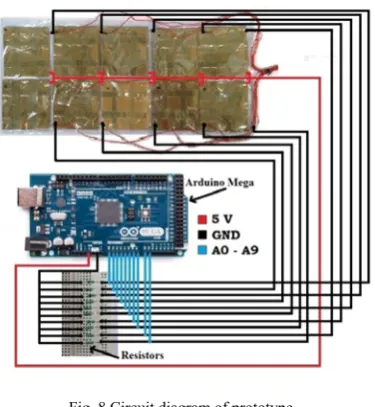
For easy handling, all the ten sensors fabricated are laminated into a thin plastic sheet, leaving the electrode wires exposed to make electrical connections, as shown in Fig. 6. A common power wire is soldered in center to ten sensors; five wires are soldered on each side to read the output voltage of each of the sensors. The output analog readings are collected by wires soldered to all ten sensors individually. They are directly connected to microcontroller without the use of multiplexers or shift registers, which can be an option when connecting higher number of sensors.
3. Circuit diagram
A voltage divider circuit is used to connect the sensors to microcontroller, as described in the data sheet provided for commercial flex sensors [8]. To identify the resistor that can be used in the circuit along with sensor in voltage divider combination, trial and error method is used. The resistor that yields most variation in the sensor output voltage, as the sensor flexes is selected. Resistors readily available were introduced into the circuit in order of ten, and it is observed that for 330 Ω, the voltage output variation is more.
Fig. 7 Voltage divider circuit
Table 1 Selection of Resistor
S. No.
Resistor R (Ohms
Ω)
Output voltage value at (A to D converted value on Arduino
microcontroller) Minimum
deflection Maximum deflection
1 47 20 450
2 330 190 800
3 3,300 800 1010
4 4,100 850 1010
5 22,000 900 1023
Arduino microcontroller converts analog 0V to 5V to a digital value with 1024 steps. So approximated digital mapped values of analog output from sensor is shown in table 1 above.
Once the resistor is selected, the circuit is made as shown in Fig. 8.
Fig. 8 Circuit diagram of prototype
4. Selection of metal sheet
5. Programming
Two programming software were used for generating the required output. Arduino IDE (Integrated development environment) was used to write code into the Arduino microcontroller. Also, to communicate the damage data visually, a sketching tool Processing was used. The below sections Arduino code and Processing code presents the way code is written to generate the required output.
5.1.Arduino Code
The analog signals from the sensors are read by analog input pins on Arduino mega board. The program is written into the microcontroller to read the analog value and send the values to a serial connected to computer. Also, the analog to digital converted value is converted to voltage as shown in Eq.1. The voltage values at variable deflections tested are used to develop an array and interpolation is used to obtain all the deflection values for voltage.
= ∗ (1)
The above equation represents the analog to digital conversion of the values read by sensors, into 1024 digital steps, being converted into voltage value.
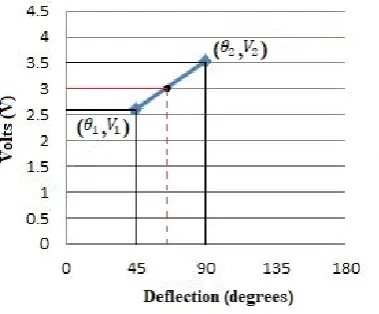
5.1.1 Voltage deflection plot
The plot is obtained from testing the sensor array for voltage obtained at different angles of deflection.
Fig. 9 Voltage Deflection plot
5.1.2 Linear interpolation
From the plot between voltage and respective deflection, since there are only a few known relation points, interpolation can be used.
Fig. 10 Interpolation
= + − ∗ – (2)
A code is written into Arduino microcontroller to read the analog to digital conversion and use them to identify deflection.
Once the analog to digital converted values are read they are converted to voltage values by the mathematical relation shown in Eq.1. To identify deflection an array is generated from the known relation of voltage and deflection. The elements of the array can be used to interpolate various values of voltage to approximated deflections by using the Eq.2. All the sensor readings and corresponding deflections are stored to be later used in visual communication of damage in the processing software.
5.2.Processing code
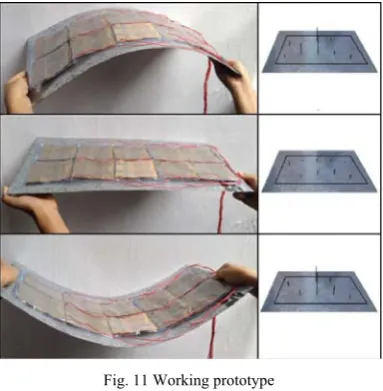
Code was written in Processing software, to sketch a visual interface that can show the sensor readings as spikes at particular sensor location. The code sketches a rectangle in 3D space and marks ten points to draw a spike whose length is proportional to analog output of sensor. The arrangement of the points resembles the sensor location on metal sheet.
Ten sensor values and ten deflection values calculated by the Arduino microcontroller are read by establishing a serial in the processing software. A picture of the actual sheet used is set as background image in the processing software interface, and a rectangle is drawn to show the working area, where sensors are located on the actual sheet as shown in Fig. 11.
Ten lines that represent value of sensors are shown that can show relative deflection from one sensor to another sensor. If the line is longer, the deflection at that sensor is more, and comparing the line lengths, the location of larger deflection can be identified and the pattern of damage can be assumed. To do this line command is used taking the first point of line at the location of the sensor and the second point’s z-coordinate is given the value of the sensor.
Also, the approximated deflections are displayed at the location of the sensors, by using the data from serial and using the command text available in processing.
After the code is written, Fig. 11 shows the deflection translated into the visual interface. In the first and last case where the deflection is more at center, the same is shown in terms of length of spike. In second case, the sheet is flat and spikes are set back to minimum positions.
Fig. 11 Working prototype
Conclusion
A new shape for flex sensor has been conceptualized to identify damage in two dimensions. The sensor has been fabricated using Velostat plastic. Programming has been written to identify the deformation of ten sensors and visually communicate data. The sensor array has been tested on sample metal sheet.
References
[1] J. S. Neely and P. J. Restle. Capacitive bend sensor, US Patent, US 5610528, Mar. 11, 1997.
[2] S. Alapati and S. N. Yeole. A Review on Applications of Flex Sensor, International Journal of Emerging Technology and Advanced Engineering, Vol.7, Issue 7, pp. 99-102.
[3] R. Barba, Á. P. de Madrid, and J. G. Boticario. (2015): Development of an Inexpensive Sensor Network for Recognition of Sitting Posture, International Journal of Distributed Sensor Networks, Volume 2015.
[4] J. Qi and L. Buechley (2010): Electronic Popables: Exploring Paper-Based Computing through an Interactive Pop-Up Book, Proceedings of Fourth International Conference on Tangible, Embedded, and Embodied Interaction, pp. 121-128.
[5] E. Jeong, J. Lee and D. E. Kim. (2011): Finger-gesture Recognition Glove using Velostat,” International Conference on Control, Automation and Systems, Gyeonggi-do, Korea, pp. 206-210.
[6] H. Baumgartel, A. Kneifela, S. Gontscharova and K. L. Kriegera. (2014): Investigations and comparison of noise signals to useful signals for the detection of dents in vehicle bodies by sound emission analysis, Procedia Technology, pp. 716-725.
[7] J. White, C. Thompson, H. Turner, B. Dougherty, and D. C. Schmidt. WreckWatch: Automatic Traffic Accident Detection and Notification with Smartphones, Journal of Mobile Networks and Applications, Volume 16.
[8] Flexpoint, Flex sensor data sheet, Available: https://www.sparkfun.com/datasheets/Sensors/Flex/flex22.pdf.
[9] Indra Rai Sharma, Sheet metal stamping in automotive industry, Available: https://drishtikona.files.wordpress.com/2012/08/ch5.pdf [10] L. K. Simone, S. Nappinnai, X. Luo, Y. Jia and D. G. Kamper. (2007): A low cost instrumented glove for extended monitoring and
functional hand assessment, Journal of Neuroscience Methods, pp. 335-348.
[11] G. Saggio. (2014): A novel array of flex sensors for a goniometric glove, Sensors and Actuator A: Physical, pp. 119-125.
[12] Flexpoint, Bend Sensor Technology Electronic Interface Design Guide, Available: http://www.flexpoint.com/wp-content/uploads/2015/10/Electronic-Design-Guide_150928.pdf
[13] Flexpoint, Bend Sensor Technology Mechanical Application Design Guide, Available: http://www.flexpoint.com/wp-content/uploads/2015/09/Mechanical-Design-Guide_091615.pdf
[14] Arduino, Available: https://www.arduino.cc/en/Guide/HomePage [15] Processing, Available: https://processing.org/reference/