focus
opportunistic software systems development
Balancing
Opportunities and
Risks in
Component-Based Software
Development
Barry Boehm, University of Southern California
Jesal Bhuta, Infosys
The Incremental
Commitment
Model provides a
process framework
for successful
opportunistic
software
development and
decision-making. It’s
based on balancing
opportunities and
risks in software
development projects.
I
ncreasingly rapid IT changes require software development projects to continuously
monitor and adapt to new sources of opportunity and risk. Projects that do not
capitalize on new opportunities will generally find their products unable to compete.
Projects that do not assess and manage their risks will generally find themselves
awash in rework, overruns, and product defects.
With respect to expected value of a software- intensive system, opportunity and risk are two sides of the same coin. For any new source of potential loss in system value, the risk exposure RE equals P(Loss) ∗ S(Loss), where P(Loss) is the probability that the new development will decrease the system’s value and S(Loss) is the resulting loss. Similarly, for any new source of potential value gain, the op-portunity exposure OE equals P(Gain) ∗ S(Gain), where P(Gain) is the probability that the new devel-opment will increase the system’s value and S(Gain) is the resulting gain.
Potential sources of value gain include improved commercial-off-the-shelf (COTS) products, reusable components from corporate or open source reposi-tories, maturing open standards, strategic partner-ships, and Web 2.0 mashups. The value gain might come in the form of faster time to market, reduced life-cycle costs, stronger capabilities, or increased customer satisfaction. On the other hand, losses in system value might emerge from user-interface
dis-continuities, complications in vendor support or in-tellectual property rights, increased life-cycle costs from losing evolutionary control, and increased development costs—often accompanied by perfor-mance losses—because of architectural mismatch among components.
A good example of the risks of architectural mismatch in component mashups was the Aesop system.1 It wasa mashup of a GUI builder, an
ob-ject-oriented database management system, and two middleware packages, which was supposed to take 6 months and 1 person-year. Because of mis-matches in architectural styles, component inter-faces, and assumptions about ownership of control, the mashup ended up taking 2 years and 5 person-years to produce something that was sluggish in performance and hard to modify.
The Incremental Commitment Model (ICM) provides a process framework to improve project monitoring and decision-making based on balanc-ing opportunities and risks.2,3 We’ve developed an
ICM-based framework and automated tool that specifically identify the risks in architectural mis-matches in component-based system development.
The ICM Process Framework
To adapt rapidly and successfully to increasing rates of change, projects must be able to assess and manage opportunities and risks; requirements,
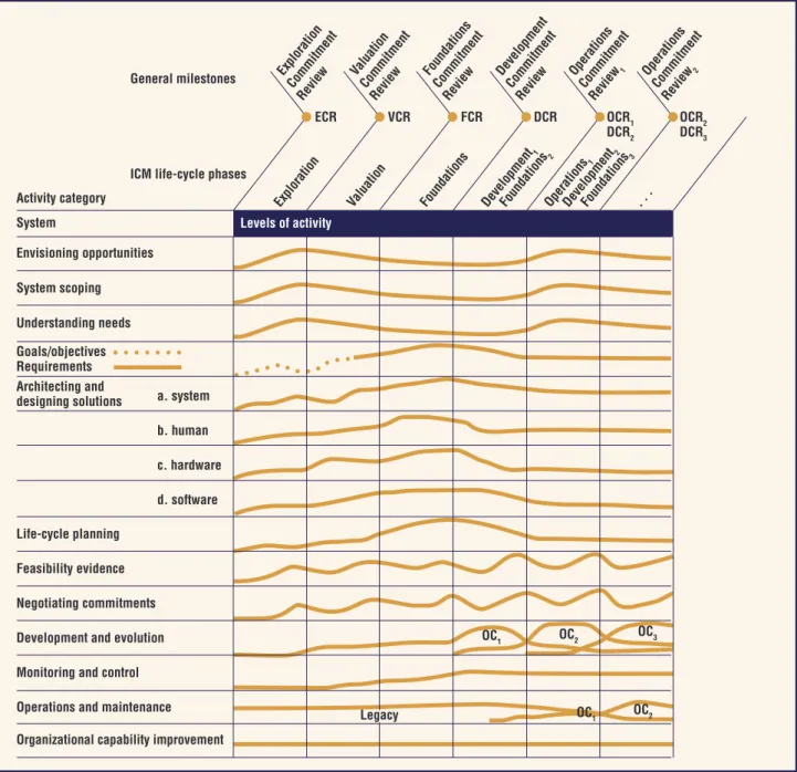
so-lutions, plans, and business cases; and hardware, software and human factors concurrently rather than sequentially. Figure 1 illustrates ICM levels of effort in concurrent activities over a project life cycle. The illustration builds on Philippe Kruchten’s “hump” diagram for the Rational Unified Process (RUP).4
As with RUP, the magnitude and shape of ICM
ECR VCR FCR DCR OCR1
DCR2
OCR2 DCR3 General milestones
ICM life-cycle phases Activity category System Envisioning opportunities System scoping Understanding needs Goals/objectives Requirements Architecting and designing solutions Life-cycle planning Feasibility evidence Negotiating commitments Development and evolution Monitoring and control Operations and maintenance Organizational capability improvement
a. system b. human c. hardware d. software Explora tion Com mitmen t Review Valuation Comm itmen t Review Founda tions Com mitment Review Commitm ent Review Operati ons Commitm ent Review 1 Operations Com mitment Review 2 Levels of activity Developmen t1 Foun dations 2 Developmen t2 . . . Foun dations 3 Operation s1 Explora tion Valuation Founda tions Develo pmen t OC1 OC2 OC1 OC2 OC3 Legacy
Figure 1. Incremental Commitment Model levels of effort. The levels of effort for success-critical activities vary over a project life cycle. The general milestone reviews synchronize concurrent activities. At these reviews, the system’s key stakeholders review feasibility evidence from the preceding phase to determine whether to commit their resources to proceeding with the next phase. The DCR and OCR subscripts indicate that for each increment, the stakeholders review the feasibility of committing to the operation of the currently developed increment and to the development of the next increment. The subscripted operational capability (OC) callouts refer to the levels of effort devoted to the development-and-evolution and operations-and-maintenance activities of each OC increment.
levels of effort are risk-driven and likely to vary from project to project. In particular, they’re likely to have many small, short-lived risk- and oppor-tunity-driven peaks and valleys, rather than the smooth curves shown for simplicity in Figure 1. Figure 1 mainly emphasizes the necessary con-currency of the primary success-critical activities listed down the left column. So, in the exploration phase, a primary activity is system scoping. But scoping systems well also involves considerable ef-fort in the activities of envisioning opportunities, understanding needs, identifying and reconciling stakeholder goals and objectives, architecting so-lutions, life-cycle planning, evaluating alterna-tives, and negotiating stakeholder commitments.
For example, to explore the initial scoping of a system of systems (SoS) for a metropolitan ar-ea’s disaster-relief effort, you wouldn’t just inter-view stakeholders and compile a list of their ex-pressed mission needs. You would also explore opportunities for reusing parts of other metro-politan-area relief systems as well as for obtaining development funds from federal agencies and for applying virtual-collaboration technologies. In the activity to understand needs, you would concur-rently assess the capability and compatibility of existing local disaster-relief systems to determine which ones would need the least work to reengi-neer into a SoS. You would assess each existing system’s scope of authority and responsibility to determine whether the best approach would be a truly integrated, centrally managed SoS or a best-effort interoperable set of systems. Other concur-rent activities might include exploring alternative architectural concepts for developing and evolving
the best early benefits and foundations for future growth; evaluating relative feasibility, benefits, and risks for stakeholders to review; and negoti-ating resource commitments to proceed into the valuation phase.
Similar concurrency applies to all projects— from large SoSs to small, time-constrained Web applications. Every year, we use the ICM to teach software engineering by having over a dozen stu-dent teams define, design, develop, and deploy Web applications for real clients in a fixed 24-week time period with a 92 percent success rate.
Synchronizing
Concurrent Engineering
The anchor-point milestone review at the end of each life-cycle phase is the ICM mechanism for synchronizing, stabilizing, and assessing risk.5,6
These reviews, labeled across the top of Figure 1, focus on developer-produced evidence along with PowerPoint charts and Unified Modeling Language (UML) diagrams. The evidence helps key stakeholders determine the next level of commitment.
Consider a system requirement to complete a real-time, safety-critical task in one second. De-velopers in this case must provide evidence based on prototyping, benchmarking, modeling, or sim-ulation using representative workloads. The evi-dence must show that the as-designed system will meet the task-completion time requirement. This differs from a promise to “build it now and tune it later,” which is frequently the practice in ad hoc or agile development. If the requirement were for a 1-second desirable, 3-seconds acceptable user- response time for a noncritical system, agile meth-ods would generally be fine.
The Exploration Commitment Review (ECR) focuses on an exploration-phase plan that includes the proposed scope, schedule, deliverables, and re-source commitments by a key subset of stakehold-ers. The plan content is risk-driven and might be only a single page for a small, uncontroversial ex-ploration for which the risk of getting it wrong is minimal. A riskier exploration phase would require a more detailed plan outlining how the project will evaluate and manage the risk of going forward.
The Valuation Commitment Review (VCR) is similarly risk-driven. The content includes the exploration-phase results and a valuation-phase plan, and the review includes all valuation-phase stakeholders.
Both the Foundations Commitment Review
Evidenceprovided by the developer and validated by independent experts that if the system is built to the specified architecture, it will
— satisfy the requirements: capability, interfaces, level of service, and evolution; — support the operational concept;
— be buildable within the plan’s budgets and schedules; — generate a viable return on investment;
— generate satisfactory outcomes for all the success-critical stakeholders. Shortfalls in evidence are sources of risk:
— All major risks are resolved or covered by risk-management plans. Risk items and risk-mitigation strategies serve as a basis for the stakeholders’ commitment to proceed.
Figure 2. Pass/fail feasibility evidence description. The FED provides a checklist to help stakeholders determine where independent experts are needed to review the criteria for stakeholders’ commitment to proceed.
(FCR) and the Development Commitment Review (DCR) are based on the highly successful AT&T Architecture Review Board procedures.6 The FCR
elaborates only high-risk aspects of the operational concept, requirements, architecture, and plans. The FCR requires evidence that at least one com-bination of those artifacts satisfies the feasibility-evidence criteria shown in Figure 2 (similar to the RUP life-cycle objectives milestone). At the DCR, developers must demonstrate that the particular choice of artifacts to be used for development will satisfy the feasibility-evidence criteria.
risk-Driven Commitment Milestones
Figure 2 emphasizes that shortfalls in feasibility evi-dence are sources of risk and so require risk-man-agement plans. Stakeholders must consider the
de-gree of risk in going forward to the next phase as the key decision criterion for committing their re-sources to it.
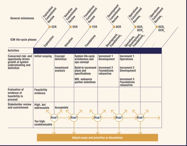
Figure 3 presents an overview of the ICM life-cycle process. Like Figure 1, it identifies the concur-rently engineered life-cycle phases, the stakeholder commitment review points, and the use of ity rationales to assess the compatibility, feasibil-ity, and risk associated with the concurrent-engi-neering artifacts. Each review point offers several alternatives:
The risks are negligible, and no further analysis or evaluation activities are needed to proceed to the next life-cycle phase.
The risk is acceptable, and work can proceed to the next phase.
■
■
Figure 3. The Incremental Commitment Model life-cycle processes. The ICM identifies the concurrently engineered life-cycle phases, the anchor-point reviews for stakeholder commitments, and the risk-based decision options
stakeholders have for proceeding to the next phase, skipping the next phase, extending the current phase, or deciding to either terminate or rescope the project if the risks are too high or unaddressable.
ECR VCR FCR DCR OCR1
DCR2 OCRDCR23 General milestones
ICM life-cycle phases Activities
Concurrent risk- and opportunity-driven growth of system understanding and definition Initial scoping Feasibility evidence Concept
definition System life-cyclearchitecture and ops concept
Increment 1
Development Increment 1Operations Investment analysis Acceptable Build-to increment plans and specifications Increment 2 Foundations rebaseline Increment 2 Development NDI, outsource
partner selections Increment 3Foundations rebaseline Evaluation of evidence of feasibility to proceed Explora tion Comm itmen t Review Valuation Comm itmen t Review Founda tions Com mitment Review Commitm ent Review Operati ons Commitm ent Review 1 Operations Com mitment Review 2 Developmen t1 Foun dations 2 Developmen t2 . . . Foun dations 3 Operation s1 Explora tion Valuation Founda tions Develo pmen t High, but addressable Too high, unaddressable Stakeholder review and commitment
Risk? Risk? Risk? Risk? Risk?
The risk is too great and requires rescoping or halting the development process.
The system’s success-critical stakeholders as-sess these risks. They base their commitment on whether the current system definition gives suffi-cient evidence that the system will satisfy their value propositions. Many risk-driven paths exist through the life cycle. A more risk-seeking set of stakehold-ers will tend to go forward or skip phases at a deci-sion point. For the same risk level, more risk-averse stakeholders might choose to extend the previous phase, rescope, or discontinue the project.
opportunity and risk Management
alternatives: a CotS Example
Suppose that at a project’s beginning, an opportu-nity exists to choose either a higher-performance COTS product B or a comparable but lower- performance COTS product C. A pure opportu-nistic approach would choose B and have C as a fallback. However, during integration, the proj-ect finds out that B has serious architproj-ectural mis-matches with another project-essential COTS product A. This will cause project overruns of 3 months and US$300K.
During integration, the probability of the mis-match is 1.0, so it’s not a risk but a problem. But earlier, its probability was uncertain, and an early ICM milestone review would have identified it as a source of risk. In accordance with the FED (see Figure 2), it would require a risk-management plan, which could use one or more of the main risk- mitigation strategies—namely, buying informa-tion, risk avoidance, risk transfer, risk reducinforma-tion, or risk acceptance. In general, buying information is the best strategy to try first because it provides more insight into which other strategies to employ. We illustrate these five strategies with our COTS example. (Other COTS-specific process guidelines are less specific about how COTS-integration risks drive development decisions. The ICM provides ways for strengthening their application.7–10)
Buying information. The project decides to spend $30K prototyping the integration of COTS pack-ages B and C with COTS package A. It finds the ar-chitectural mismatches between A and B as well as the likely costs and schedules to resolve them. It also finds that COTS package C would integrate easily with A, but with a 10 percent performance loss. This information enables the stakeholders to better evaluate the other risk mitigation strategies.
■ delivery. So, the project proceeds with COTS
prod-uct C rather than B.
Risk transfer. The customer decides that the perfor-mance increase is worth the extra time and money and establishes a risk reserve of 3 months and $300K. These are used if they’re needed during in-tegration, but the developer receives award fees to the extent that fewer resources are needed.
Risk reduction. The developer and customer agree to integrate A and B in parallel early in the proj-ect, with added cost but with no delay in delivery schedule.
Risk acceptance. The developer decides that having a proprietary solution to integrating A and B will provide a competitive edge on future projects, and decides to fund and patent the solution.
Assessing Software
Integration Risks
The risk-mitigation strategies show different op-portunistic solutions resulting from different stakeholder value propositions. The following as-sessment framework and corresponding tool, Inte-gration Studio (iStudio),11 offer a strategy to
bal-ance risks and opportunities for the example we highlighted earlier.
The framework is modeled using three compo-nents: a interoperability analyzer, COTS-representation attributes (to define components), and integration rules. Framework inputs are vari-ous COTS component definitions and the high-level system architecture. Output is an interoper-ability assessment report, which includes results of three major analyses:
Internal-assumption mismatch analysis, which identifies mistaken assumptions that interact-ing COTS systems make about each other’s in-ternal structure.12
Interface (or packaging) mismatch analysis, which identifies incompatible communication interfaces between two components.
Dependency analysis, which identifies facili-ties that the COTS packages used in the sys-tem require (for example, Java-based customer- relationship-management solutions require Java Runtime Engine).
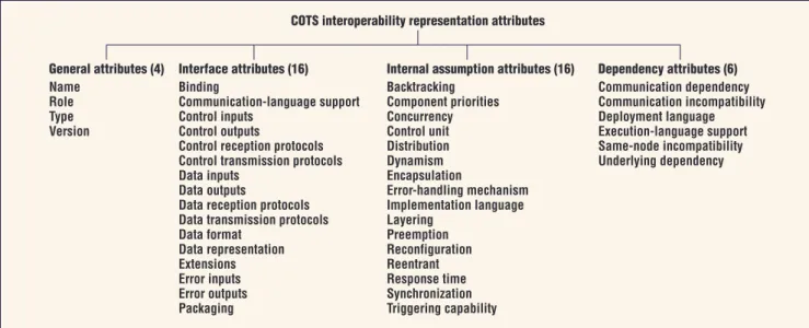
The framework identifies 42 attributes, which appear in Figure 4. These attributes define
as-■ ■ ■
The
risk-mitigation
strategies
show different
opportunistic
solutions
resulting
from different
stakeholder
value
propositions.
sumptions about components, along with their interfaces and dependencies. In addition, the framework defines 62 interoperability-analysis rules to identify architectural mismatches for a given architecture. Of these 62, 50 rules address internal-assumption mismatches, seven rules identify interface mismatches, and five rules de-tect dependency mismatches.
For example, an interface-mismatch rule de-fines a data-interaction mismatch that can occur when two interacting components exchanging data don’t support any common data-exchange connectors or protocols. When the framework (or the framework-supported tool) identifies a mis-match, it recommends possible strategies for use in resolving it. (Details of interoperability-assessment attributes and rules are available elsewhere.11)
The iStudio tool developed on the basis of this framework inputs high-level, component-based deployment architectures together with nent-interoperability characteristics. The compo-nent characteristics are based on interoperability analyses and the aforementioned attributes (in XML). iStudio specifies every interaction in the architecture by
interaction type (control and/or data),
interaction direction (unidirectional, bidirec-tional), and
interaction initiator (the component initiating the interaction).
Using the deployment architectures, iStudio deter-mines the system deployment topology as well as the distribution of COTS products. It uses the 62
■ ■ ■
interoperability analysis rules for performing archi-tecture-mismatch analysis.
Upon completing its analysis, the tool outputs a report that includes the three assessment-results groups: internal assumptions, interfaces, and de-pendencies. Developers can use this report to iden-tify the amount of effort required to integrate the COTS products. The tool also packages a Web site that lets analysts create XML-based COTS product definitions, then store and reuse them across mul-tiple architectural assessments.
COTS Assessment
and Selection Scenario
A project at NASA’s Jet Propulsion Laboratory (JPL) offers a COTS assessment and selection prob-lem derived from several existing challenges. This assessment scenario helps illustrate our frame-work’s utility and ground it in an existing real-world problem.
Four JPL planetary scientists in Pasadena, Cali-fornia, are responsible for managing several giga-bytes of planetary-science data that includes digital content and the corresponding metadata. The JPL scientists need to share their data with colleagues at the European Space Agency (ESA) in Madrid, Spain, who also manage several gigabytes of plan-etary data. In addition, thousands of external users, including other planetary scientists and educators (each with their own preferences), are customers of the data available through JPL and ESA’s indepen-dent planetary-data systems.
To support the planetary scientists’ needs, JPL and ESA commissioned a team of software ar-chitects and engineers to design and implement a
Internal assumption attributes (16)
Backtracking Component priorities Concurrency Control unit Distribution Dynamism Encapsulation Error-handling mechanism Implementation language Layering Preemption Reconfiguration Reentrant Response time Synchronization Triggering capability Dependency attributes (6) Communication dependency Communication incompatibility Deployment language Execution-language support Same-node incompatibility Underlying dependency
COTS interoperability representation attributes
Interface attributes (16)
Binding
Communication-language support Control inputs
Control outputs
Control reception protocols Control transmission protocols Data inputs
Data outputs
Data reception protocols Data transmission protocols Data format Data representation Extensions Error inputs Error outputs Packaging General attributes (4) Name Role Type Version
Figure 4. COTS interoperability representation attributes. A framework for assessing component interoperability identifies 42 attributes that define assumptions, interfaces, and dependencies about components.
Internal assumption attributes (16)
Backtracking Component priorities Concurrency Control unit Distribution Dynamism Encapsulation Error-handling mechanism Implementation language Layering Preemption Reconfiguration Reentrant Response time Synchronization Triggering capability Dependency attributes (6) Communication dependency Communication incompatibility Deployment language Execution-language support Same-node incompatibility Underlying dependency
COTS interoperability representation attributes
Interface attributes (16)
Binding
Communication-language support Control inputs
Control outputs
Control reception protocols Control transmission protocols Data inputs
Data outputs
Data reception protocols Data transmission protocols Data format Data representation Extensions Error inputs Error outputs Packaging General attributes (4) Name Role Type Version
software system that can support the data-distribu-tion tasks outlined between JPL and ESA. The sys-tem must also serve the external users.
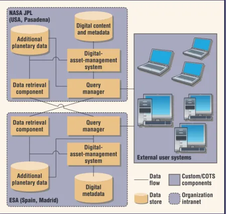
Figure 5 displays a potential architecture for such a system. The systems based at JPL and ESA use a COTS digital-asset-management system such as DSpace, data stores that include at least one type of database system such as Oracle or Sybase, and two custom components—one of which manages user queries while the other retrieves data from its counterpart system at periodic intervals.
propriate COTS components for supporting data distribution, given so many heterogeneous systems involved. Several considerations might guide the COTS technologies to deploy in such a scenario— for example, an organization’s requirements, the skill levels of programmers tasked with imple-menting the system, or even the system’s architec-ture. It’s important, however, to assess and deter-mine COTS-integration risks before developing, acquiring, and deploying the components to avoid rework caused by architecture mismatches.
Our example has two major considerations in assessing COTS products and implementation technologies to identify interoperability conflicts:
interoperability conflicts when integrating the digital-asset-management system with the da-tabase, and
language selections for developing the custom components to minimize the development ef-fort by leveraging existing support that the COTS products provide.
To address these two considerations, the ana-lyst will use the iStudio tool and provide the fol-lowing information for every interaction in the proposed architecture:
data and/or control interaction,
unidirectional or bidirectional interaction, and
which component initiates the interaction. Assume an assessment scenario where DSpace is the digital-asset-management system and MySQL is the database server. The analyst will provide the definitions for DSpace and MySQL and define the deployment architecture, along with various component interactions, using the iStudio tool for assessment. (Figure 6 shows a snapshot of the tool interface.)
Our framework’s integration-analysis compo-nent will use COTS attributes and the deployment architecture definition and apply the rules from the integration-rules repository to identify
common interfaces supported by MySQL and DSpace, bridging connectors and the required glue-code type (communication, conversion, coordination, or a combination thereof);11 for
example, DSpace and MySQL lack a common data-communication interface, so this will re-quire glue code.
■ ■ ■ ■ ■ ■ Figure 6. Integration Studio tool interface snapshot. The iStudio tool supports integration analysis for COTS product interactions.
ESA (Spain, Madrid)
Query manager Data retrieval component Additional planetary data Digital content and metadata (USA, Pasadena) Digital-asset-management system Data flow Data store Custom/COTS components Organization intranet Additional planetary data Digital-asset-management system Query manager Data retrieval component Digital metadata
External user systems
Figure 5. A potential architecture for a large-scale data-distribution scenario. The architecture supports planetary scientists’ needs at NASA’s Jet Propulsion Laboratory and the European Space Agency in Madrid as well as thousands of external users.
internal-assumption mismatches between MySQL and DSpace;11 for example, ifeither
MySQL or DSpace is inactive while the other is transmitting information, the system will lose thisdata. Another example occurs when data being transferred from MySQL is later back-tracked, causing system inconsistencies. COTS dependencies and verify that they’ve been satisfi ed in the given architecture. recommended languages for the query man-ager and data-retrieval component to simplify glue-code development between COTS and custom components. For example, the tool will recommend that custom components, such as query-manager and data-retrieval components, be built using Java because DSpace supports it. In this example, where the two interacting com-ponents (DSpace and MySQL) lack common in-terfaces, the framework and iStudio tool will rec-ommend a connector requirement that can enable communication between the two components (in this case, a JDBC-MySQL driver). Our framework-iStudio tool will output these fi ndings in a report for the project analyst. The project analyst can use these fi ndings to determine the software integration risks if the project selects the given components for implementation.
S
oftware projects and organizations can increase their success rates in software development by better assessing and bal-ancing their opportunities and risks. By requiring early evidence that opportunistic approaches to software development are feasible (where possible via tools, such as iStudio, and otherwise via COTS integration experiments or prototypes), the ICM can help projects determine whether attractive op-tions such as Web 2.0 mashups are likely to lead to satisfying success or frustrating failure.References
1. D. Garlan, R. Allen, and J. Ockerbloom, “Architectural
Mismatch: Why Reuse Is So Hard,” IEEE Software,
vol. 12, no. 6, 1995, pp. 17–26.
2. R.W. Pew and A.S. Mavor, Human-System
Integra-tion in the System Development Process: A New Look, Nat’l Academy Press, 2007.
3. B. Boehm and J. Lane, “Using the Incremental Commit-ment Model to Integrate System Acquisition, Systems
Engineering, and Software Engineering,” CrossTalk,
Oct. 2007, pp. 4–9.
4. P. Kruchten, The Rational Unifi ed Process, Addison-Wesley, 1999.
5. B. Boehm, “Anchoring the Software Process,” IEEE
Software, vol. 13, no. 4, 1996, pp. 73–82. ■
■ ■
6. M. Maranzano et al., “Architecture Reviews: Practice
and Experience,” IEEE Software, vol. 22, no. 2, 2005,
pp. 34–43.
7. C. Albert and L. Brownsword, Evolutionary Process
for Integrating COTS-Based Systems (EPIC): An Overview, tech. report CMU/SEI2002-TR-009, Carnegie-Mellon Univ., July 2002.
8. B.C. Meyers and P. Oberndorf, Managing Software
Acquisition: Open Systems and COTS Products, Addison-Wesley, 2002.
9. K. Wallnau, S. Hissam, and R. Seacord, Building
Sys-tems from Commercial Components, Addison-Wesley, 2002.
10. Y. Yang et al., “Value-Based Processes for COTS-Based Applications,” IEEE Software, vol. 22, no. 4, 2005, pp. 54–62.
11. J. Bhuta, “A Framework for Intelligent Assessment and Resolution of Commercial-Off-The-Shelf Product Incompatibilities,” doctoral dissertation, Computer Science Dept., Univ. of Southern California, 2007. 12. C. Gacek, “Detecting Architectural Mismatches during
Systems Composition,” doctoral dissertation, Computer Science Dept., Univ. of Southern California, 1998.
About the Authors
Barry Boehm is the TRW professor of software engineering in the University of South-ern California’s Computer Science Department and the director of its Center for Systems and Software Engineering. His research interests involve recasting systems and software engi-neering into a value-based framework. Boehm received his PhD in mathematics from UCLA. He’s a fellow of the IEEE, ACM, AIAA, and International Council on Systems Engineering, and a member of the US National Academy of Engineering. Contact him at [email protected].
Jesal Bhuta is a senior associate with Infosys Consulting. His research interests in -clude commercial-off-the-shelf based software development and risk management. Bhuta received his PhD in computer science from University of Southern California. Contact him at [email protected].
• 14 magazines—one source
• Free peer-reviewed articles
• Blogs, podcasts, & more!
http://computingnow.
computer.org
computer.org
computer.org