ECLIPSE DSC+ GX1100E
25 Watt VHF/FM Class D DSC Marine Transceiver
Owner's Manual
Affordable Ultra Compact Fixed Mount VHF radioSubmersible IPX7 Front Panel
DSC (Digital Selective Calling) Class D with Position Report and Re-quest
Programmable Scan, Priority Scan, and Dual Watch
Dot Matrix Display of various indication includes the GPS Latitude/Lon-gitude shown
Simple Operation
All USA / International and Canadian Marine Channels
TABLE OF CONTENTS
1 GENERAL INFORMATION ... 4 2 PACKING LIST ... 4 3 OPTIONS ... 4 4 INSTALLATION NOTE ... 5 5 GETTING STARTED ... 6 5.1 ABOUT VHF RADIO ... 6 5.2 SELECTING AN ANTENNA ... 6 5.3 COAXIAL CABLE ... 7 6 INSTALLATION ... 8 6.1 LOCATION ... 86.2 MOUNTING THE RADIO ... 8
6.2.1 Supplied Universal Mounting Bracket ... 8
6.2.2 Optional MMB-84 Flash Mount Bracket ... 9
6.3 ELECTRICAL CONNECTIONS ... 10
6.4 ACCESSORY CABLE ... 11
6.5 CHECKING GPS CONNECTIONS ... 11
6.6 CHANGING THE GPS TIME ... 12
6.7 CHANGING THE TIME LOCATION ... 13
7 CONTROLS AND INDICATORS ... 14
8 BASIC OPERATION ... 18
8.1 RECEPTION ... 18
8.2 TRANSMISSION ... 18
8.3 TRANSMIT TIME-OUT TIMER (TOT) ... 18
8.4 SIMPLEX / DUPLEX CHANNEL USE ... 19
8.5 INTERNATIONAL, USA, AND CANADA MODE ... 19
8.6 EMERGENCY (CHANNEL 16 USE) ... 19
8.7 CALLING ANOTHER VESSEL (CHANNEL 16 OR 9) ... 20
8.8 MAKING TELEPHONE CALLS ... 21
8.9 OPERATING ON CHANNELS 13 AND 67 ... 21
8.10 SCANNING ... 21
8.10.1 Selecting the Scan Type ... 21
8.10.2 Memory Scanning (M-SCAN) ... 22
9 DIGITAL SELECTIVE CALLING ... 24
9.1 GENERAL ... 24
9.2 MARITIME MOBILE SERVICE IDENTITY (MMSI) ... 24
9.2.1 What is an MMSI? ... 24
9.2.2 Programming the MMSI ... 25
9.3 DISTRESS ALERT ... 26
9.3.1 Tansmitting a Distress Alert ... 26
9.3.2 Receiving a Distress Alert ... 28
9.4 ALL SHIPS CALL ... 30
9.4.1 Transmitting an All Ships Call ... 30
9.4.2 Receiving an All Ships Call ... 31
9.5 INDIVIDUAL CALL ... 32
9.5.1 Setting up the Individual / Position Call Directory ... 32
9.5.2 Setting up Individual Ringer ... 33
9.5.3 Setting up Individual / Group Call Ringer ... 34
9.5.4 Transmitting an Individual Call ... 35
9.5.5 Receiving an Individual Call ... 37
9.6 CALL WAITING DIRECTORY ... 38
9.6.1 Enabling / Disabling the Call Waiting Feature ... 38
9.6.2 Reviewing Received Calls Logged into the Call Waiting Directory ... 38
9.6.3 To Delete the Received Log from the “DSC Log” Directory .... 39
9.7 GROUP CALL ... 40
9.7.1 Setting up a Group Call ... 40
9.7.2 Transmitting a Group Call ... 41
9.7.3 Receiving a Group Call ... 43
9.8 POSITION REQUEST ... 44
9.8.1 Setting up Position Reply ... 44
9.8.2 Transmitting a Position Request to Another Vessel ... 45
9.8.3 Receiving a Position Request ... 47
9.9 POSITION REPORT ... 48
9.9.1 Setting up Position Report Ringer ... 48
9.9.2 Transmitting a DSC Position Report Call ... 49
9.9.3 Receiving a DSC Position Report Call ... 50
9.10 DSC TRANSMISSION TEST ... 51
9.11 MANUAL INPUTTING OF THE GPS LOCATION (LAT/LON) ... 52
10 RADIO SETUP MODE ... 53
10.1 LAMP ADJUSTING ... 53
10.2 LCD CONTRAST ... 53
10.3 TIME OFFSET ... 54
10.4 TIME DISPLAY ... 55
10.5 PRIORITY CHANNEL SET ... 55
10.6 SCAN TYPE ... 56
10.7 KEY BEEP (ON/OFF) ... 56
11 PROGRAMMING THE ATIS CODE ... 57
12 MAINTENANCE ... 59 12.1 REPLACEMENT PARTS ... 59 12.2 FACTORY SERVICE ... 59 12.3 TROUBLESHOOTING CHART ... 60 13 CHANNEL ASSIGNMENTS ... 61 14 SPECIFICATIONS ... 65
TABLE OF CONTENTS
1 GENERAL INFORMATION
The Vertex Standard GX1100E ECLIPSE DSC+ is a VHF/FM transceiver de-signed for use in the frequency range of 156.025 to 163.275 MHz. The GX1100E can be operated from 10.8 to 15.6 VDC and has a switchable RF output power of 1 watt or 25 watts.
The GX1100E is capable of DSC (Digital Selective Calling) Class D operation which allows continuous receiving of Digital Selective Calling functions on chan-nel 70 even if the radio is receiving a call.
2 PACKING LIST
When the package containing the transceiver is first opened, please check it for the following contents:
GX1100E Transceiver
Mounting Bracket and attaching hardware
Power Cord
Owner’s Manual
Warranty Card
3 OPTIONS
MMB-84... Flush-Mount Bracket MLS-310... Amplified External Speaker MLS-300... External Loudspeaker
4 INSTALLATION NOTE
The installation of this equipment should be made in such a manner as to re-spect the EC recommended electromagnetic field exposure limits (1999/519/ EC).
The maximum RF power available from this device is 25 watts. The antenna should be installed as high as possible for maximum efficiency and that this installation height should be at least 5 meters above ground (or accessible) level. In the case that an antenna can not be installed at a reasonable height, then the transmitter should neither be continuously operated for long periods if any person is within 5 metres of the antenna, nor operated at all if any person is touching the antenna.
In all cases any possible risk depends on the transmitter being activated for long periods (actual recommendation limits are specified as an average of 6 minutes). Normally the transmitter is not active for long periods of time. Some radio licenses will require that a timer circuit automatically cuts the transmitter after 1 - 2 minutes.
5 GETTING STARTED
5.1 ABOUT VHF RADIO
The radio frequencies used in the VHF marine band lie between 156 and 158 MHz with some shore stations available between 161 and 163 MHz. The ma-rine VHF band provides communications over distances that are essentially “line of sight” (VHF signals do not travel well through objects such as buildings, hills or trees). Actual transmission range depends much more on antenna type, gain and height than on the power output of the transmitter. On a fixed mount 25W radio transmission expected distances can be greater than 25 km.
5.2 SELECTING AN ANTENNA
Marine antennas are made to radiate signals equally in all horizontal directions, but not straight up. The objective of a marine antenna is to enhance the signal toward the horizon. The degree to which this is accomplished is called the antenna’s gain. It is measured in decibels (dB) and is one of the major factors in choosing an antenna. In terms of effective radiated power (ERP), antennas are rated on the basis of how much gain they have over a theoretical antenna with zero gain. A 1 m, 3dB gain antenna represents twice as much gain over the imaginary antenna.
Typically a 1 m 3dB gain stainless steel whip is used on a sailboat mast. The longer 2.5 m 6dB fibreglass whip is primarily used on power boats that require the additional gain.
5.3 COAXIAL CABLE
VHF antennas are connected to the transceiver by means of a coaxial cable – a shielded transmission line. Coaxial cable is specified by it’s diameter and construction.
For runs less than 6 m, RG-58/U, about 6 mm in diameter is a good choice. For runs over 6 m but less than 15 m, the larger RG-8X should be used for cable runs over 15 m RG213 should be used. For installation of the connector onto the coaxial cable refer to the figure below.
To get your coax cable through a fitting and into your boat’s interior, you may have to cut off the end plug and reattach it later. You can do this if you follow the directions that are supplied with the connector. Be sure to make good soldered connections.
6 INSTALLATION
6.1
LOCATION
The radio can be mounted at any angle. Choose a mounting location that: • keeps the radio and microphone at least 1 m away from your vessel’s
magnetic navigation compass
• provides accessibility to the front panel controls • allows connection to a power source and an antenna • has nearby space for installation of a microphone hanger • the antenna must be mounted at least 1 m from radio
Note: To insure the radio does not affect the compass, or that radios perfor-mance is not affected by the antenna location, temporarily connect the radio in the desired location and:
a. Examine the compass to see if the radio causes any deviation
b. Connect the antenna and key the radio. Check to ensure the radio is operating correctly by requesting a radio check.
6.2 MOUNTING THE RADIO
6.2.1 Supplied Universal Mounting Bracket
The supplied universal mounting bracket allows overhead or desktop mounting. Use a 5.2-mm bit to drill the holes to a surface which is more 10 mm thick and can support more than 5 kg and secure the bracket with the supplied screws, spring washers, flat washers, and nuts.
6.2.2 Optional MMB-84 Flush Mount Bracket
1. To assist in flush mounting, a template has been included. Use this tem-plate to assess the mounting location.
2. Use the template to mark the location where the rectangular hole is to be cut. Confirm the space behind the dash or panel is deep enough to accom-modate the transceiver (at least 15 cm deep).
There should be at least 1.5 cm between the transceiver’s heatsink and any wiring, cables or structures.
3. Cut out the rectangular hole and insert the transceiver.
4. Fasten the brackets to the sides of the transceiver with the lock washer nut combination; so that the mounting screw base faces the mounting surface. 5. Turn the adjusting screw to adjust the tension so that the transceiver is tight
against the mounting surface.
MMB-84 Flush Mount Installation
Bracket
Adjusting Screw
6.3 ELECTRICAL CONNECTIONS
CAUTION
Reverse polarity connections will damage the radio!
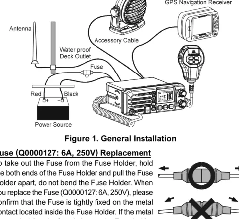
Connect the power cord and antenna to the radio. Antenna and Power Supply connections are as follows (see Figure 1):
1. Mount the antenna at least 1 m away from the radio. At the rear of the radio, connect the antenna cable.
2. Connect the red power wire to a 10.8 VDC ~ 15.6 VDC power source. Connect the black power wire to a negative ground.
3. If an optional remote extension speaker is to be used, refer to next section for connections.
4. It is advisable to have a Certified Marine Technician check the power output and the standing wave ratio of the antenna after installation.
Figure 1. General Installation Fuse (Q0000127: 6A, 250V) Replacement
To take out the Fuse from the Fuse Holder, hold the both ends of the Fuse Holder and pull the Fuse Holder apart, do not bend the Fuse Holder. When you replace the Fuse (Q0000127: 6A, 250V), please confirm that the Fuse is tightly fixed on the metal contact located inside the Fuse Holder. If the metal contact holding the fuse is loose, the Fuse holder may heat up.
GPS Navigation Receiver Accessory Cable Optional Speaker Antenna Fuse Red Power Source Black Water proof Deck Outlet
6.4 ACCESSORY CABLE
When connecting the external speaker or GPS navigation receiver, strip off about 2.5 cm of the specified wire’s insulation, then splice the ends together using proper waterproofing techniques.
• The GPS must have the NMEA Output turned on and set to 4800 Baud in the setup menu. If there is a selection for parity select none.
• For further information on interfacing /setting up your GPS. Please contact the manufacturer of the GPS receiver.
• GX1100E can read NMEA-0183 version 2.0 or higher. • The NMEA supported sentences are:
Input: GLL, GGA, RMC and GNS (RMC sentence is recommended) Output: DSC and DSE
(DSC sentences to Standard Horizon Plotter for Position Polling)
6.5 CHECKING GPS CONNECTIONS
After connections have been made between the GX1100E and the GPS, a small satellite icon will ap-pear on the top right corner of the display, and dis-plays your current location (Latitude/Longitude) on the display.
Wire Color/Description WHITE - External Speaker (+) SHIELD - External Speaker (–) BLUE- NMEA Input (+) GREEN - NMEA Input (–) PURPLE - NMEA Output (+)
Connection Examples
Connect to external 4 Ohm audio speaker Connect to external 4 Ohm audio speaker Connect to NMEA (+) output of GPS Connect to NMEA ground of GPS Connect to NMEA (+) input of GPS
GPS Receiver External Speaker Green Purple Blue Shield White Plotter Connection Radio Wires NMEA OUT NMEA COMMON NMEA IN ( ) ( ) ( )
6.6 CHANGING THE GPS TIME
From the Factory the GX1100E shows GPS satellite time or UTC time. A time offset is needed to show the local time in your area.
1. Press and hold down the [CALL(MENU)] key until “SETUP MENU” appears.
2. Press the [ENT] key, then select “TIME OFFSET” with the [(UP)] / [(DOWN)] keys.
3. Press the [ENT] key.
4. Press the [(UP)] / [(DOWN)] keys to select time offset from UTC. See illustration below to find your offset time from UTC. If “00:00” is assigned, the time is the same as UTC (Universal Time Co-ordinated or GMT Greenwich Mean Time). 5. Press the [ENT] key to store the time offset. 6. Press the [16/9] key to exit the menu mode and
return to radio operation.
6.7 CHANGING THE TIME LOCATION
Sets the radio to show UTC time or Local time with the offset inputted in section 6.6 Changing the GPS Time.
1. Press and hold down the [CALL(MENU)] key until “SETUP MENU” appears.
2. Press the [ENT] key, then select “TIME DISPLAY” with the [(UP)] / [(DOWN)] keys.
3. Press the [ENT] key.
4. Press the [(UP)] / [(DOWN)] to select “UTC” or “LOCAL”.
5. Press the [ENT] key to store the selected setting. 6. Press the [16/9] key to exit the menu mode and
return to radio operation.
In the Local time mode, the display shows the time by the 12-hour system. Meanwhile, the display shows the time by the 24-hour system in the UTC time mode.
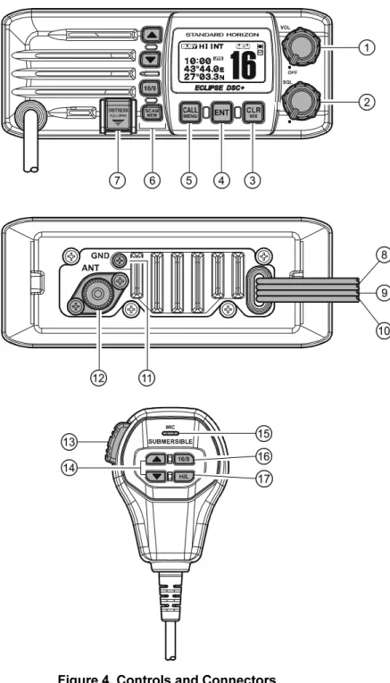
7 CONTROLS AND INDICATORS
NOTE
This section defines each control of the transceiver. See Figure 4 for location of controls. For detailed operating instructions refer to section “8 BASIC OPERATION.”
POWER SWITCH / VOLUME CONTROL (VOL/PWR)
Turns the transceiver on and off as well as adjusts the audio volume. Turn this knob clockwise to turn the radio on and increase the speakers audio volume level.
Turn fully counter-clockwise to turn the radio off. SQUELCH CONTROL (SQL)
Adjusting this control clockwise, sets the point at which random noise on the channel does not activate the audio circuits but a received signal will. This point is called the squelch threshold. Further adjustment of the squelch control will degrade reception of wanted transmissions.
[CLR(WX)] Key
Press the [CLR(WX)] Key to cancel the menu selection.
The secondary function of the [CLR(WX)] Key (WX function) does not work on the GX1100E.
[ENT] Key
Press the [ENT] Key to determine the menu selection. [CALL(MENU)] Key
Press the [CALL(MENU)] key to access the “DSC MENU”. The “INDIVIDUAL CALL”, “GROUP CALL”, “ALL SHIPS CALL”, “POS REQUEST”, “POS REPORT”, “DSC LOG”, and “DSC TEST” functions can be accessed from the “DSC MENU”. NOTE: Before the “DSC MENU” menu can be selected a MMSI must be entered. Refer to section “9.2 MARITIME MOBILE SERVICE IDENTITY (MMSI).”
Secondary use
Press and hold the [CALL(MENU)] key to access the “SETUP MENU”. The “RADIO SETUP” (refer to section “10 RADIO SETUP MODE”), “DSC SETUP”, “POS INPUT”, and “MMSI SETUP” functions can be accessed from the “SETUP MENU”.
KEYPAD
[(UP)] / [(DOWN)] KEYS
The [(UP)] and [(DOWN)] keys are used to select a desired chan-nel and to select items in the DSC OPERATION and SETUP menus. [16/9] Key
Immediately recalls channel 16 from any channel location and auto-matically selects high power. Holding down this key recalls channel 9. Pressing the [16/9] key again reverts to the previous selected working channel.
Secondary use
Press and hold the [16/9] key then press the [CLR] key to switch be-tween the USA, Canadian, and International Channel Groups.
[SCAN(MEM)] Key
Press this key to start and stop the scanning of programmed channels. Refer to section “8.10 SCANNING” for details.
Secondary use
To add a channel into the scan memory, select the channel and press and hold the [SCAN(MEM)] key until “MEM” is shown on the display. To delete a memorised channel from scan memory, select the channel and press and hold the [SCAN(MEM)] key until “MEM” is removed from the display.
[DISTRESS] Key
Used to send a DSC Distress Call. To send the distress call refer to section “9.3.1 (Transmitting A Distress Alert).”
DC INPUT CABLE
Connects the radio to a DC power supply capable of delivering 12V DC. EXTERNAL SPEAKER CONNECTION CABLE
Connects the GX1100E to an external speaker. GPS RECEIVER CONNECTION CABLE Connects the GX1100E to a GPS receiver. GND TERMINAL
Connects the GX1100E to a good ground, for safety and optimum perfor-mance.
Install only the supplied screw or similar size (M3x6, Stainless Steel) screw.
ANTENNA JACK
Connects an antenna to the transceiver. Use a marine VHF antenna with an impedance of 50 ohms.
MICROPHONE
Transmits the voice message with reduction of background noise, using Clear Voice Noise Reduction Technology.
NOTE: Be sure your mouth is about 1.5 cm from the mic hole for best performance.
PTT (Push-To-Talk) SWITCH
Keys the transmitter when the transceiver is in radio mode. [(UP)] / [(DOWN)] KEYS
The [(UP)] and [(DOWN)] keys on the microphone function the same as the [(UP)] and [(DOWN)] keys on the front panel of the transceiver. [16/9] Key
The [16/9] key on the microphone functions the same as the [16/9] key on the front panel of the transceiver.
Immediately recalls channel 16 from any channel location. Holding down this key recalls channel 9. Pressing the [16/9] key again reverts to the pre-vious selected working channel.
[H/L] Key
Press this key to toggle the transmit output power between 25 W (High) and 1 W (Low) power. When the [H/L] key is pressed while the transceiver is on channel 13 or 67, the power will temporarily switch from LO to HI power until the PTT is released.
The [H/L] key does not function on transmit inhibited and low power only channels.
NOTE: 1W low power is indicated by LO on the display, when 25W high power is selected the display do not show an indication.
8 BASIC OPERATION
8.1 RECEPTION
1. After the transceiver has been installed, ensure that the power supply and antenna are properly connected.
2. Turn the VOL/PWR knob clockwise to turn the transceiver on.
3. Turn the SQL knob fully counterclockwise. This state is known as “squelch off”. 4. Turn up the VOL knob until noise or audio from the speaker is at a
comfort-able level.
5. Turn the SQL knob clockwise until the random noise disappears. This state is known as the “squelch threshold.”
6. Press the [(UP)] or [(DOWN)] keys to select the desired channel. Refer to the channel chart on page 61 for available channels.
7. When a message is received, adjust the volume to the desired listening level. The “ ” indicator in the LCD is displayed indicating that the chan-nel is being used.
8.2 TRANSMISSION
1. Perform steps 1 through 6 of RECEPTION.
2. Before transmitting, monitor the channel to ensure it is clear.
3 Press the PTT (push-to-talk) switch. The “ ” indicator in the LCD is displayed.
4. Speak slowly and clearly into the microphone. NOTE
We recommend that the duty cycle (TX:RX) is “1 : 3” or less. 5. When the transmission is finished, release the PTT switch.
NOTE
This is a noise cancelling microphone. The oval slot on the bottom of microphone should be positioned within 1.5 cm from the mouth for opti-mum performance.
8.3 TRANSMIT TIME - OUT TIMER
(
TOT
)
When the PTT switch on the microphone is held down, transmit time is limited to 5 minutes. This limits unintentional transmissions due to a stuck microphone. About 10 seconds before automatic transmitter shutdown, a warning beep will be heard from the speaker(s). The transceiver will automatically go to receive mode, even if the PTT switch is continually held down. Before transmitting again, the PTT switch must first be released and then pressed again.
NOTE
When a transmission was shut down by the TOT, the GX1100E can not transmit afterwards for 10 seconds.
8.4 SIMPLEX/DUPLEX CHANNEL USE
Refer to the VHF MARINE CHANNEL CHART (page 62) for instructions on use of simplex and duplex channels.
NOTE
All channels are factory-programmed in accordance with International, Industry Canada (Canada), and FCC (USA) regulations. Mode of opera-tion cannot be altered from simplex to duplex or vice-versa.
8.5 INTERNATIONAL, USA, AND CANADA MODE
1. To change the modes, hold the [16/9] key and press the [CLR(WX)] key. The mode changes from “International” to “Canadian” to “USA” with each press of the [CLR(WX)] key.
2. “INTL” will be displayed for International mode, “CAN” will be displayed for Canadian mode, and “USA” will be displayed on the LCD for USA mode. 3. Refer to the VHF MARINE CHANNEL CHART (page 62) for allocated channels in each mode.
NOTE
This function does not work depending on the transceiver’s version.
8.6 EMERGENCY
(
CHANNEL 16 USE
)
Channel 16 is known as the Hail and Distress Channel. An emergency is de-fined as a threat to life or property. In such instances, be sure the transceiver is on and set to CHANNEL 16. Then use the following procedure:
1. Press the microphone push-to-talk switch and say “Mayday, Mayday, May-day. This is , , ” (your vessel’s name).
2. Then repeat once: “Mayday, ” (your vessel’s name).
3. Now report your position in latitude/longitude, or by giving a true or mag-netic bearing (state which) to a well-known landmark such as a navigation aid or geographic feature such as an island or harbour entry.
4. Explain the nature of your distress (sinking, collision, aground, fire, heart attack, life-threatening injury, etc.).
5. State the kind of assistance you desire (pumps, medical aid, etc.). 6. Report the number of persons aboard and condition of any injured. 7. Estimate the present seaworthiness and condition of your vessel.
INTERNATIONAL MODE
CANADIAN MODE
8. Give your vessel’s description: length, design (power or sail), colour and other distinguishing marks. The total transmission should not exceed 1 minute. 9. End the message by saying “OVER.” Release the microphone button and
listen.
10. If there is no answer, repeat the above procedure. If there is still no re-sponse, try another channel.
8.7 CALLING ANOTHER VESSEL
(
CHANNEL 16 OR 9
)
Channel 16 may be used for initial contact (hailing) with another vessel. However, its most important use is for emergency messages. This channel must be monitored at all times except when actually using another channel. It is monitored by the European, U.S. and Canadian Coast Guards and by other vessels. Use of channel 16 for hailing must be limited to initial contact only. Calling should not exceed 30 seconds, but may be repeated 3 times at 2-minute intervals. In areas of heavy radio traffic, congestion on channel 16 re-sulting from its use as a hailing channel can be reduced significantly in U.S. waters by using channel 9 as the initial contact (hailing) channel for non-emer-gency communications. Here, also, calling time should not exceed 30 seconds but may be repeated 3 times at 2-minute intervals.
Prior to making contact with another vessel, refer to the channel charts in this manual, and select an appropriate channel for communications after initial con-tact. For example, Channels 68 and 69 are some of the channels available to non-commercial (recreational) boaters. Monitor your desired channel in advance to make sure you will not be interrupting other traffic, and then go back to either channel 16 or 9 for your initial contact.
When the hailing channel (16 or 9) is clear, state the name of the other vessel you wish to call and then “this is” followed by the name of your vessel and your Station License (Call Sign). When the other vessel returns your call, immedi-ately request another channel by saying “go to,” the number of the other chan-nel, and “over.” Then switch to the new channel. When the new channel is not busy, call the other vessel.
After a transmission, say “over,” and release the microphone’s push-to-talk (PTT) switch. When all communication with the other vessel is completed, end the last transmission by stating your Call Sign and the word “out.” Note that it is not necessary to state your Call Sign with each transmission, only at the begin-ning and end of the contact.
Remember to return to Channel 16 when not using another channel. Some radios automatically monitor Channel 16 even when set to other channels or when scanning.
8.8 MAKING TELEPHONE CALLS
To make a radiotelephone call, use a channel designated for this purpose, The fastest way to learn which channels are used for radiotelephone traffic is to ask at a local marina. Channels available for such traffic are designated Public Correspondence channels on the channel charts in this manual. Some ex-amples for USA use are Channels 24, 25, 26, 27, 28, 84, 85, 86, and 87. Call the marine operator and identify yourself by your vessel’s name, The marine operator will then ask you how you will pay for the call (telephone credit card, collect, etc.) and then link your radio transmission to the telephone lines. The marine telephone company managing the VHF channel you are using may charge a link-up fee in addition to the cost of the call.
8.9 OPERATING ON CHANNELS 13 AND 67
Channel 13 is used at docks and bridges and by vessels manoeuvering in port. Messages on this channel must concern navigation only, such as meeting and passing in restricted waters.
Channel 67 is used for navigational traffic between vessels.
By regulation, power is normally limited to 1 Watt on these channels. Your radio is programmed to automatically reduce power to this limit on these channels. However, in certain situations it may be necessary to temporarily use a higher power. See page 17 ([H/L] key) for means to temporarily override the low-power limit on these two channels.
8.10 SCANNING
Allows the user to select the scan type from Memory scan or Priority scan. “Memory scan” scans the channels that were programmed into memory. “Prior-ity scan” scans the channels programmed in memory with the prior“Prior-ity channel.
8.10.1 Selecting the Scan Type
1. Press and hold down the [CALL(MENU)] key until “SETUP MENU” appears.
2. Press the [ENT] key, then select “SCAN TYPE” in the “RADIO SETUP” menu with the [(UP)] / [(DOWN)] keys.
3. Press the [ENT] key.
4. Press the [(UP)] / [(DOWN)] keys to se-lect “PRIORITY SCAN” or “MEMORY SCAN.” 5. Press the [ENT] key to store the selected setting. 6. To exit this menu and return to radio operation
8.10.2 Memory Scanning (M-SCAN)
1. Adjust the SQL knob until background noise disappears.
2. Select a desired channel to be scanned using the [(UP)] / [(DOWN)] keys.
3. Press and hold the [SCAN(MEM)] key for one second, “MEM” will appear on the LCD which indicates the channel has been
programmed into the transceivers memory. 4. Repeat steps 2 and 3 for all the desired channels
to be scanned.
5. To DELETE a channel from the transceiver’s memory, select the channel then press and hold the [SCAN(MEM)] key for one second, “MEM” will disappear in the LCD.
6. To start scanning, just press the [SCAN(MEM)] key momentarily. “M-SCAN” appears on the LCD. Scanning will proceed from
the lowest to the highest programmed channel number and will stop on a channel when a trans-mission is received.
7. The channel number will blink during reception. 8. To stop scanning, press the [16/9] or [CLR(WX)] key.
8.10.3 Priority Scanning (P-SCAN)
In the default setting, Channel 16 is set as the priority channel. You may change the priority channel to another channel from Channel 16 in the Radio Setup Mode, refer to section “10.6 PRIORITY CHANNEL SET.”
1. Adjust the SQL knob until background noise disappears.
2. Select a desired channel to be scanned using the [(UP)] / [(DOWN)] keys.
3. Press and hold the [SCAN(MEM)] key for one second, “MEM” will appear on the display which indicates the channel has
been programmed into the transceivers memory. 4. Repeat step 2 for all the desired channels to be
scanned.
5. To DELETE a channel from the transceiver’s memory, select the channel then press and hold the [SCAN(MEM)] key until “MEM” is removed from the display.
6. To start priority scanning, just press the [SCAN(MEM)] key momentarily. “P-SCAN” appears on the LCD. Scanning will proceed between the memorized channels and the priority channel. The
priority channel will be scanned after each programmed channel. 7. To stop scanning, press the [16/9] or [CLR(WX)] key.
Priority Channel Setting
1. Press and hold down the [CALL(MENU)] key until “SETUP MENU” appears.
2. Press the [ENT] key, then select “PRIORITY CH” in the “RADIO SETUP” menu with the [(UP)] / [(DOWN)] keys.
3. Press the [ENT] key.
4. Press the [(UP)] / [(DOWN)] keys to select the Priority channel.
5. Press the [ENT] key to store the selected setting.
6. Press the [16/9] key to exit the menu mode and return to radio operation.
9 DIGITAL SELECTIVE CALLING
9.1 GENERAL
WARNING
This radio is designed to generate a digital maritime distress and safety call to facilitate search and rescue. To be effective as a safety device, this equipment must be used only within communication range of a shore-based VHF marine channel 70 distress and safety watch system. The range of signal may vary but under normal conditions should be approxi-mately 20 nautical miles.
Digital Selective Calling is a semi-automated method of establishing a radio call, it has been designated by the International Maritime Organization (IMO) as an international standard for establishing VHF, MF, and HF radio calls. It has also been designated as part of the Global Maritime Distress and Safety Sys-tem (GMDSS). It is planned that DSC will eventually replace aural watches on distress frequencies and will be used to announce routine and urgent maritime safety information broadcasts.
This new system allows mariners to instantly send a distress call with GPS posi-tion (when connected to the transceiver) to the Coast Guard and other vessels within range of the transmission. DSC will also allow mariners to initiate or receive Distress, Urgency, Safety, Routine, POSITION REQUEST, POSITION SEND, and Group calls to or from another vessel equipped with a DSC transceiver.
9.2 MARITIME MOBILE SERVICE IDENTITY
(
MMSI
)
9.2.1 What is an MMSI?An MMSI is a nine digit number used on Marine Transceivers capable of using Digital Selective Calling (DSC). This number is used like a telephone number to selectively call other vessels.
THIS NUMBER MUST BE PROGRAMMED INTO THE RADIO TO OPERATE THE GX1100E DSC FUNCTIONS.
How can I obtain an MMSI assignment?
Please contact the Radio Licensing Authority for your country for information on how to obtain an MMSI number.
9.2.2 Programming the MMSI
WARNING
A User MMSI can be input only once. Therefore, please be careful not to input the incorrect MMSI number. If the user needs to change the MMSI number after it has been entered, the radio will have to be returned to Factory Service. Refer to the section “11.2. FACTORY SER-VICE.”
1. Press and hold down the [CALL(MENU)] key until the “SETUP MENU” appears. 2. Press the [(DOWN)] key repeatedly until
the “MMSI SETUP” menu appears.
3. Press the [ENT] key. The display will show a se-ries of dashes.
4. Press the [(UP)] / [(DOWN)] keys to se-lect the first number of your MMSI, then press the [ENT] key to step to the next num-ber.
5. Repeat step 4 to set your MMSI (up to nine digits).
6. When finished programming the number, press and hold the [ENT] key. A confirma-tion message appears on the display. Set your MMSI again, then press and hold the [ENT] key.
7. Press the [ENT] key to store the number in memory and return to radio operation mode.
9.3 DISTRESS ALERT
The GX1100E is capable of transmitting and receiving DSC Distress messages to all DSC radios. The GX1100E may be connected to a GPS to also transmit the Latitude and Longitude of the vessel.
9.3.1 Transmitting a Distress Alert
NOTE
To be able to transmit a Distress Alert an MMSI number must be pro-grammed, refer to section “9.2.2 Programming the MMSI.”
In order for your vessels location to be transmitted either connect a GPS to the GX1100E (refer to section “6.4 ACCESSORY CABLE”) or manually input your postion (refer to section “9.11 MANUAL INPUTTING OF THE GPS LOCA-TION”).
1. Lift the red spring loaded DISTRESS cover, then press and hold the [DISTRESS] key. The “ DIS-TRESS” menu will appear on the LCD and the ra-dios display will count down (3S 2S 1S) and then transmit the Distress Alert. The backlight of the LCD and keypad flashes while the radios dis-play is countdown.
2. The transceiver will watch for a DSC acknowledg-ment transmission on CH70 and also receive calls on CH16.
3. If an acknowledgement is received, select chan-nel 16 and advise your distress situation.
4. If no acknowledgment is received, the Distress Alert is repeated at approximately 4 minute inter-vals until a DSC acknowledgment is received. 5. When a DSC Distress acknowledgment is
re-ceived, a DSC Distress Alarm sounds and channel 16 is automatically se-lected. The LCD shows the MMSI of the ship responding to your distress. RECEIVED ACK: acknowledgment signal is received.
RECEIVED RLY ACK: relay acknowledgment signal is received from another vessel or coast station.
Transmitting a Distress Alert with Nature of Distress
The GX1100E is capable of transmitting a Distress Alert with the following “Na-ture of Distress” categories:
Undesignated, Fire, Flooding, Collision, Grounding, Capsizing, Sinking, Adrift, Abandoning, Piracy, Mob
1. Lift the red spring loaded DISTRESS cover and press the [DISTRESS] key. The “DISTRESS” menu will appear on the LCD.
2. Press the [ENT] key.
3. Press the [(UP)] / [(DOWN)] keys to select the desired nature of distress category, then press the [ENT] key.
4. Press and hold the [DISTRESS] key. The radios display will count down (3S 2S 1S) and then transmit the Distress Alert. The backlight of the LCD and keypad flashes while the radios display is countdown.
5. The transceiver will watch for a DSC acknowledg-ment transmission on CH70 and also receive calls on CH16.
6. If an acknowledgement is received, select chan-nel 16 and advise your distress situation.
7. If no acknowledgment is received, the Distress Alert is repeated in 4 minute intervals until a DSC acknowledgment is received.
8. When a DSC Distress acknowledgment is re-ceived, a distress alarm sounds and channel 16 is automatically selected. The LCD shows the MMSI of the ship responding to your distress.
RECEIVED ACK: acknowledgment signal is received.
RECEIVED RLY ACK: relay acknowledgment signal is received from another vessel or coast station.
9. To cancel the DSC distress alarm signal from the speaker, press any key.
Cancel a Distress Alert
In order to cancel the repeat call function of the DSC, press the [CLR(WX)] key, then press the [ENT] key.
9.3.2 Receiving a Distress Alert
1. When a Distress Alert is received, an emergency alarm sounds. The display will show the MMSI (or name) of the
vessel transmitting the Distress and the radio au-tomatically switches to channel 16.
2. Press any key to stop the alarm.
3. Press the [(DOWN)] key to change the display to show the “Nature of Distress” and position of the vessel.
4. If the position of the vessel distress data does not include position, the LCD will show “NO POSITION”.
NOTE
When there is an unread Distress Alert, the “DSC” icon will blink. You may review the unread Distress Alert from the DSC Log, refer to section “9.6.2 Reviewing Received Calls Logged into the Call Waiting Di-rectory.”
NOTE
You must continue monitoring channel 16 as a coast station may require assistance in the rescue attempt.
9.4 ALL SHIPS CALL
The All Ships Call function allows contact to be established with other vessel stations without having their ID in the individual calling directory. Also, priority for the call can be designated as Urgency or Safety.
URGENCY Call: This type of call is used when a vessel may not truly be in distress, but have a potential problem that may lead to a dis-tress situation. This call is the same as saying PAN PAN PAN on channel 16.
SAFETY Call: Used to transmit boating safety information to other vessels. This message usually contains information about an overdue boat, debris in the water, loss of a navigation aid or an impor-tant meteorological message. This call is the same as saying Securite, Securite, Securite.”
9.4.1 Transmitting an All Ships Call
1. Press the [CALL(MENU)] key. The “DSC MENU” will appear.
2. Press the [(UP)] / [(DOWN)] keys to se-lect “ALL SHIPS.”
3. Press the [ENT] key. (To cancel, press the [CLR] key)
4. Press the [(UP)] / [(DOWN)] keys to se-lect the call (“SAFETY” or “URGENY”), then press the [ENT] key.
5. Press the [(UP)] / [(DOWN)] keys to se-lect the operating channel you want to com-municate on, then press the [ENT] key. 6. Press the [ENT] key again to transmit the
selected call type of ALL SHIPS CALL. 7. After the ALL SHIPS CALL is transmitted,
the transceiver will switch to the channel which is selected on step 5 above (but, the display will not change. To change the dis-play, press the [CLR(WX)] key).
8. Listen to the channel to make sure it is not busy, then key the microphone and say PAN PAN PAN or “Securite, Securite, Securite” depend-ing on the priority of the call. Say your call sign and announce the channel you wish to switch to for communications.
9.4.2 Receiving an All Ships Call
1. When an All Ships Call is received, an emergency alarm sounds. The display will show the MMSI (or name) of the
vessel transmitting the All Ships Call and the radio automatically switches to the requested channel (but, the display will not change).
2. Press any key to stop the alarm.
3. Press the [(DOWN)] key to display the “Nature of Call”.
4. Press the [CLR(WX)] key to display the operating channel number of the requested channel. 5. Press the PTT switch on the microphone and talk
9.5 INDIVIDUAL CALL
This feature allows the GX1100E to contact another vessel with a DSC VHF radio and automatically switch the receiving radio to a desired communications channel. This feature is similar to calling a vessel on CH16 and requesting to go to another channel (switching to the channel is private between the two stations).
9.5.1 Setting up the Individual / Position Call Directory
The GX1100E has a DSC directory that allows you to store a vessel or person’s name and the MMSI number associated with vessels you wish to transmit Indi-vidual calls, Position Requests and Position Send transmissions.
To transmit an Individual call you must program this directory with the informa-tion of the persons you wish to call, similar to a cellular phones directory. 1. Press and hold down the [CALL(MENU)] key until
“SETUP MENU” appears.
2. Press the [(UP)] / [(DOWN)] keys to select “DSC SETUP” menu.
3. Press the [ENT] key, then select “INDIV DIR” with the [(UP)] / [(DOWN)] keys.
4. Press the [ENT] key, then select “ADD” with the [(UP)] / [(DOWN)] keys.
5. Press the [ENT] key.
6. Press the [(UP)] / [(DOWN)] keys to scroll to the first letter of the name of the vessel or person you want to list in the directory.
7. Press the [ENT] key to store the first letter of the name and step to the next letter to the right. 8. Repeat step 6 and 7 until the name is complete.
The name can consist of up to eleven characters, if you do not use all eleven characters press the [ENT] key to move to the next space. This method can also be used to enter a blank space in the name. To clear the previous letter, press the [CLR(WX)] key.
9. After the eleventh letter or space has been entered, press and hold the [ENT] key to advance to the MMSI number (Maritime Mobile Service Identity Number) entry.
10. Press the [(UP)] / [(DOWN)] keys to scroll through numbers, 0-9. To enter the desired
num-ber and move one space to the right press the [ENT] key. Repeat this proce-dure until all nine spaces of the MMSI number are entered.
11. If a mistake was made entering in the name or the MMSI number repeat pressing the microphone’s [H/L] key until the wrong character is selected, then press the [(UP)] / [(DOWN)] keys to correct the entry.
12. To store the data entered, press and hold the [ENT] key.
13. To enter another individual address, repeat steps 4 through 12.
14. To exit this menu and return to radio operation mode press the [16/9] key.
9.5.2 Setting up Individual Reply
Allows setting up the radio to automatically (default setting) or manually re-spond to a DSC Individual call requesting you to switch to a working channel for voice communications. When Manual is selected the MMSI of the calling ves-sel is shown allowing you to see who is calling. This function is similar to caller id on a cellular phone.
1. Press and hold down the [CALL(MENU)] key until “SETUP MENU” appears.
2. Press the [(UP)] / [(DOWN)] keys to se-lect “DSC SETUP” menu.
3. Press the [ENT] key, then select “INDIV RE-PLY” with the [(UP)] / [(DOWN)] keys. 4. Press the [ENT]key.
5. Turn the [(UP)] / [(DOWN)] keys to se-lect “AUTO” or “MANUAL.”
6. Press the [ENT] key to store the selected setting.
7. To exit this menu and return to radio operation mode press the [16/9] key.
9.5.3 Setting up the Individual/Group Call Ringer
When a Individual Call or Group Call is received the radio will produce a ringing tone for 3 minutes. This selection allows the Individual Call ringer time to be changed.
1. Press and hold down the [CALL(MENU)] key until “SETUP MENU” appears.
2. Press the [(UP)] / [(DOWN)] keys to se-lect “DSC SETUP” menu.
3. Press the [ENT] key, then select “INDIV RING” with the [(UP)] / [(DOWN)] keys. 4. Press the [ENT] key.
5. Press the [(UP)] / [(DOWN)] keys to se-lect ringing time of a Individual Call.
6. Press the [ENT] key to store the selected setting. 7. To exit this menu and return to radio operation
mode press the [16/9] key.
The GX1100E has the capability to turn off the Individual call ringer. 1. Press and hold down the [CALL(MENU)]
key until “SETUP MENU” appears.
2. Press the [(UP)] / [(DOWN)] keys to select “DSC SETUP” menu.
3. Press the [ENT] key, then select “DSC BEEP” with the [(UP)] / [(DOWN)] keys. 4. Press the [ENT] key.
5. Press the [(UP)] / [(DOWN)] keys to select “INDIVIDUAL” if you wish to disable the Individual Call ringer, or “GROUP” if you wish to disable the Group Call ringer and press the [ENT] key.
6. Press the [(UP)] / [(DOWN)] keys to select “OFF.”
7. Press the [ENT] key to store the selected setting. 8. To exit this menu and return to radio operation
mode press the [16/9] key.
If you wish to return to enabling the ringer tone, just repeat the above proce-dure, pressing the [(UP)] / [(DOWN)] keys to select “ON” in step “6” above.
9.5.4 Transmitting an Individual Call
This feature allows the user to contact another vessel with a DSC radio. This feature is similar to calling a vessel on CH16 and requesting to go to another channel.
Pre-Programmable Calling
1. Press the [CALL(MENU)] key. The “DSC MENU” will appear.
2. Press the [(UP)] / [(DOWN)] keys to select “INDIVIDUAL”. (To cancel, press the [16/9] or [CLR] key.)
3. Press the [ENT] key. The transceiver will beep, and the “Individual directory” will appear.
4. Press the [(UP)] / [(DOWN)] keys to select the “Individual” you want to contact.
5. Press the [ENT] key, then press the [(UP)] / [(DOWN)] keys to select the operating channel you want to communicate on and press the [ENT] key.
6. Press the [ENT] key again to transmit the individual DSC signal.
7. After INDIVIDUAL CALL is transmitted, if the reply signal is not received, “WAIT FOR ACK” notation will show on the display. To send the call again, press the [(DOWN)] key followed by the [ENT] key.
8. When an individual call acknowledgment is re-ceived, the established channel is automatically changed to the channel which is selected on step 5 above and a ringing tone sounds.
9. Press the [CLR(WX)] key to listen to the channel to make sure it is not busy, then key the micro-phone and call the other vessel you desire to com-municate with.
Manual Calling
You may enter an MMSI number manually to contact without storing it in the Individual Directory.
1. Press the [CALL(MENU)] key. The “DSC MENU” will appear.
2. Press the [(UP)] / [(DOWN)] keys to select “INDIVIDUAL”. (To cancel, press the [16/9] or [CLR(WX)] key.)
3. Press the [ENT] key. The transceiver will beep, and the “Individual directory” will appear.
4. Press the [(UP)] / [(DOWN)] keys to select “MANUAL”, then press the [ENT] key.
5. Press the [(UP)] / [(DOWN)] keys to scroll through numbers, 0-9. To enter the desired num-ber and move one space to the right, press the [ENT] key. Repeat this procedure until all nine spaces of the MMSI number which you want to contact are entered.
6. If a mistake was made entering in the MMSI num-ber repeat pressing the microphone’s [H/L] key until the wrong number is selected, then move the chan-nel knob to correct the entry.
7. When finished entering the MMSI number, press and hold the [ENT] key.
8. Press the [ENT] key, then press the [(UP)] / [(DOWN)] keys to select the operating channel you want to communicate on and press the [ENT] key. 9. Press the [ENT] key again to transmit the individual
DSC signal.
10. After INDIVIDUAL CALL is transmitted, if the reply signal is not received, “WAIT FOR ACK” notation will show on the display. To send the call again, press the [(DOWN)] key followed by the [ENT] key. 11. When an individual call acknowledgment is
re-ceived, the established channel is automatically changed to the channel which is selected on step 8 above and a ringing tone sounds.
12. Press the [CLR(WX)] key to listen to the channel to make sure it is not busy, then key the
9.5.5 Receiving an Individual Call
When receiving an individual call, an acknowledgment must be sent back to the calling station. The GX1100E default setting is Automatic, but has a selection that allows you to manually send a reply before the radio will switch to the requested calling channel. This selection is useful if you want to see who is calling and requesting you to switch to a channel for communications, similar to caller id on a cellular phone.
1. When an individual call is received, an individual call ringing alarm sounds. The display will show the MMSI (or name) of the
vessel transmitting the Individual Call and the ra-dio automatically switches to the requested chan-nel.
2. Press any key to stop the alarm.
3. Press the [CLR(WX)] key to show the display to the operating channel number of the requested channel.
9.6 CALL WAITING DIRECTORY
The GX1100E logs received Distress Calls and Individual Calls into the Call Waiting Directory for review at a later time. The DSC Call Waiting feature is similar to an answer machine where calls are recorded
for review. When a call is logged while the radio is set on the DSC Standby function, a “ ” icon will appear on the display. The GX1100E can memorise up to the latest 20 Distress and up to the latest 38 DSC Calls.
9.6.1 Enabling/Disabling the Call Waiting Feature
Follow the steps below to enable or disable the Call Waiting feature. 1. Press and hold down the [CALL(MENU)]
key until “SETUP MENU” menu appears. 2. Press the [(UP)] / [(DOWN)] keys to
se-lect “DSC SETUP” menu.
3. Press the [ENT] key, then select “INDIV ACK” with the [(UP)] / [(DOWN)] keys. 4. Press the [ENT] key.
5. Press the [(UP)] / [(DOWN)] keys to se-lect “ABLE” or “UNABLE”.
6. Press the [ENT] key to store the selected setting. 7. To exit this menu and return to radio operation
mode press the [16/9] key.
9.6.2 Reviewing Received Calls Logged into the Call Waiting Directory
1. Press the [CALL(MENU)] key. The “DSC MENU” will appear.
2. Press the [(UP)] / [(DOWN)] keys to se-lect “DSC LOG” menu.
3. Press the [ENT] key, then press the [(UP)] / [(DOWN)] keys to select the category (“ DIS-TRESS” or “DSC CALL”) you want to review and/or call back.
4. Press the [ENT] key, then press the [(UP)] / [(DOWN)] keys to select the category (DIS-TRESS or DIST CANCEL: for “DISTRESS”) or sta-tion (name or MMSI number: for “DSC CALL”) you want to review and/or call back.
[(DOWN)] keys to review details for the selected category or station.
6. If you review the DSC Call, press the [ENT] key again, to call the selected station if de-sired.
7. To exit Call Waiting Directory and return to radio operation mode press the [CLR] key.
NOTE
When there is an unread received call, the “” icon will appear behind the unread category (“DISTRESS” or “DSC CALL”) and station name (or MMSI number).
9.6.3 To Delete the Received Log from the “DSC Log” Directory
1. Press the [CALL(MENU)] key. The “DSC MENU” will appear.
2. Press the [(UP)] / [(DOWN)] keys to select “DSC LOG” menu.
3. Press the [ENT] key, then press the [(UP)] / [(DOWN)] keys to select “LOG DELETE”.
4. Press the [ENT] key, then press the [(UP)] / [(DOWN)] keys to select the category (“ DIS-TRESS” or “DSC CALL”) to be deleted.
5. Press the [ENT] key, then press the [(UP)] / [(DOWN)] keys to select the category (DIS-TRESS or DIST CANCEL: for “DISTRESS”) or sta-tion (name or MMSI number: for “DSC CALL”) to be deleted.
6. Press and hold the [ENT] key until the category or station (name or MMSI number) is removed from the display.
9.7 GROUP CALL
This feature allows the user to contact a group of specific vessels (example members of a yacht club) with a group MMSI number using the Group call function to automatically switch to a desired channel for voice communications.
9.7.1 Setting up a Group Call
For this function to operate the same Group MMSI must be programmed into all the DSC VHF radios within the group of vessels that will be using this fea-ture. The group MMSI is a 9 digit (first digit permanently set to “0”) number that will allow other radios to call your vessel along with others to automatically switch to a working channel for voice communications. This function is very useful for yacht clubs and vessels traveling together that want to collectively make announcements on a predetermined channel.
1. Press and hold down the [CALL(MENU)] key until “SETUP MENU” menu appears.
2. Press the [(UP)] / [(DOWN)] keys to select “DSC SETUP” menu.
3. Press the [ENT] key, then select “GROUP DIR” with the [(UP)] / [(DOWN)] keys.
4. Press the [ENT] key, then select “ADD” with the [(UP)] / [(DOWN)] keys.
5. Press the [CALL(MENU)] key.
6. Press the [(UP)] / [(DOWN)] keys to scroll through the first letter of the group name you want to reference in the directory.
7. Press the [ENT] key to store the first letter in the name and step to the next letter to the right. 8. Repeat step 6 and 7 until the name is complete.
The name can consist of up to eleven characters, if you do not use all eleven characters press the [ENT] key to move to the next space. This method can also be used to enter a blank space in the name. To clear the previous letter, press the [CLR(WX)] key.
9. After the eleventh letter or space has been entered, press and hold the [ENT] key to advance to the MMSI number (Maritime Mobile Service Identity Number) entry.
10. Press the [(UP)] / [(DOWN)] keys to scroll through numbers, 0-9. To enter the desired number and move one space to the right press the [ENT]
key. Repeat this procedure until all nine space of the MMSI number are entered.
11. If a mistake was made entering in the name or the MMSI number repeat pressing the microphone’s [H/L] key until the wrong character is selected, then move the channel knob to correct the entry.
12. To store the data entered, press and hold the [ENT] key.
13. To enter another individual address, repeat steps 4 through 12.
14. To exit this menu and return to radio operation mode press the [16/9] key.
9.7.2 Transmitting a Group Call
Pre-Programmable Calling
1. Press the [CALL(MENU)] key. The “DSC MENU” will appear.
2. Press the [(UP)] / [(DOWN)] keys to se-lect “GROUP”. (To cancel, press the [16/9] key or [CLR] key.)
3. Press the [ENT] key. The transceiver will beep, and the “Group Directory” will appear. 4. Press the [(UP)] / [(DOWN)] keys to
select the “Group” you want to contact. 5. Press the [ENT] key, then press the [(UP)]
/ [(DOWN)] keys to select the operating channel you want to communicate on and press the [ENT] key.
6. Press the [ENT] key again to transmit the Group Call signal.
7. After the GROUP CALL is transmitted, all the radios in the group will switch to the channel which is selected on step 5 above (but, the display will not change).
8. Press the [CLR(WX)] key to return to radio opera-tion mode.
9. Listen to the channel to make sure it is not busy, then key the microphone and call the other ves-sels you desire to communicate with.
Manual Calling
You may enter an MMSI number manually to contact without the Setting up the Group call number.
1. Press the [CALL(MENU)] key. The “DSC MENU” will appear.
2. Press the [(UP)] / [(DOWN)] keys to se-lect “GROUP”. (To cancel, press the [16/9] key or [CLR(WX)] key.)
3. Press the [ENT] key. The transceiver will beep, and the “Group Directory” will appear. 4. Press the [(UP)] / [(DOWN)] keys to select “MANUAL”, then press the [ENT] key. 5. Press the [(UP)] / [(DOWN)] keys to scroll
through numbers, 0-9. To enter the desired num-ber and move one space to the right press the [ENT] key. Repeat this procedure until all nine space of the MMSI number which you want to con-tact are entered.
6. If a mistake was made entering in the MMSI num-ber, repeat pressing the microphone’s [H/L] key until the wrong nunber is selected, then press the [(UP)] / [(DOWN)] keys to correct the entry. 7. When finish the entering the MMSI number, press
and hold the [ENT] key.
8. Press the [ENT] key, then press the [(UP)] / [(DOWN)] keys to select the operating channel you want to communicate on and press the [ENT] key.
9. Press the [ENT] key again to transmit the Group Call signal.
10. After the GROUP CALL is transmitted, all the ra-dios in the group will switch to the channel which is selected on step 5 above (but, the display will not change).
11. Press the [CLR(WX)] key to return to radio opera-tion mod.
12. Listen to the channel to make sure it is not busy, then key the microphone and call the other ves-sels you desire to communicate with.
9.7.3 Receiving a Group Call
1. When a group call is received, the GX1100E will produce a ringing alarm sound.
The display will show the MMSI (or name) of the vessel transmitting the Group Call and the radio automatically switches to the requested channel (but, the display will not change).
2. Press any key to stop the alarm.
3. Press the [(DOWN)] key to display the “Nature of Call”.
4. Press the [CLR(WX)] key to display the operating channel number of the requested channel. 5. Monitor the channel for the person calling the
Group for a message.
6. If you want to respond, monitor the channel to make sure it is clear, then press the PTT on the mic and talk to the calling ship(s).
NOTE
When there is an unread Group Call, the “DSC” icon will blink. You may review the unread Group Call from the DSC Log, refer to section “9.6.2 Reviewing Received Calls Logged into the Call Waiting Directory.”
NOTE
After a Group call is received, the time the call was made and the ships MMSI or vessels name will appear on the LCD.
9.8 POSITION REQUEST
Advancements in DSC have made it possible to poll the location of another vessel and show the position of that vessel on the display of the GX1100E. Standard Horizon has taken this feature one step further, if any Standard Hori-zon GPS is connected to the GX1100E, the polled position of the vessel is shown on the display of the GPS chart plotter making it easy to navigate to the location of the polled vessel. This is a great feature for anyone wanting to know the position of another vessel. For example your friend that is catching fish, or finding the location of a person you are cruising with.
NOTE
The other vessel must have an operating GPS receiver connected to its DSC transceiver and must not have its transceiver set to deny position requests. (Refer the section “9.5.1 Setting up the Individual / Position Call Directory” to enter information into the individual directory).
9.8.1 Setting up Position Reply
The GX1100E can be set up to automatically or manually send your position to another vessel. This selection is important if you are concerned about some-one polling the position of your vessel that you may not want to. In the manual mode you will see the MMSI or persons name shown on the display allowing you to choose to send your position to the requesting vessel.
1. Press and hold down the [CALL(MENU)] key until “SETUP MENU” appear.
2. Press the [(UP)] / [(DOWN)] keys to se-lect “DSC SETUP” menu.
3. Press the [ENT] key, then select “POS RE-PLY” with the [(UP)] / [(DOWN)] keys. 4. Press the [ENT] key.
5. Press the [(UP)] / [(DOWN)] keys to se-lect “AUTO” or “MANUAL”. In “AUTO” mode, after a DSC POS Request is received, the radio will automatically transmit your vessels position. In “MANUAL” mode, the display of the GX1100E will show who is requesting the position.
6. Press the [ENT] key to store the selected setting.
The GX1100E has the capability to turn off the Position Request ringer. 1. Press and hold down the [CALL(MENU)]
key until “SETUP MENU” appears.
2. Press the [(UP)] / [(DOWN)] keys to se-lect “DSC SETUP” menu.
3. Press the [ENT] key, then select “DSC BEEP” with the [(UP)] / [(DOWN)] keys. 4. Press the [ENT] key.
5. Press the [(UP)] / [(DOWN)] keys to se-lect “POS REQUEST”.
6. Press the [ENT] key.
7. Press the [(UP)] / [(DOWN)] keys to select “OFF”.
8. Press the [ENT] key to store the selected setting.
9. To exit this menu and return to radio operation mode press the [16/9] key.
If you wish to return to enabling the ringer tone, just repeat the above proce-dure, pressing the [(UP)] / [(DOWN)] keys to select “ON” in step “7” above.
9.8.2 Transmitting a Position Request to Another Vessel
Pre-Programmable Request
1. Press the [CALL(MENU)] key. The “DSC MENU” will appear in the display.
2. Press the [(UP)] / [(DOWN)] keys to se-lect “POS REQUEST”.
3. Press [ENT] key to show the Position request di-rectory. This directory uses the INDIVIDUAL Di-rectory information.
4. Press the [(UP)] / [(DOWN)] keys to se-lect a name, then press the [ENT] key. 5. Press the [ENT] key to transmit the position
request DSC call.
6. When the GX1100E receives the position from the polled vessel, the GX1100E will produce a ringing alarm sound and the po-sition from the polled vessel transferred to the GPS Chart plotter.
8. Press the [(DOWN)] key to show the position from the polled vessel transferred on the display. 9. If the GX1100E does not receive a reply, the
dis-play will be as shown in the illustration on the right. To send again, press the [ENT] key.
NOTE
If the GX1100E does not receive position data from the polled vessel, the LCD will show “NO POSITION DATA.”
Manual Request
You may enter an MMSI number manually to contact without the Setting up the Individual / Position Call Directory.
1. Press the [CALL(MENU)] key. The “DSC MENU” will appear in the display.
2. Press the [(UP)] / [(DOWN)] keys to select “POS REQUEST”.
3. Press [ENT] key to show the Position request di-rectory. This directory uses the INDIVIDUAL Di-rectory information.
4. Press the [(UP)] / [(DOWN)] keys to select the “MANUAL”, then press the [ENT] key.
5. Press the [(UP)] / [(DOWN)] keys to scroll through numbers, 0-9. To enter the desired num-ber and move one space to the right press the [ENT] key. Repeat this procedure until all nine space of the MMSI number which you want to con-tact are entered.
6. If a mistake was made entering in the MMSI num-ber repeat pressing the microphone’s [H/L] key until the wrong nunber is selected, then press the [(UP)] / [(DOWN)] keys to correct the entry. 7. When finished entering the MMSI number, press
and hold the [ENT] key.
8. Press the [ENT] key to transmit the position re-quest DSC call.
9. When the GX1100E receives the position from the polled vessel, the GX1100E will produce a ringing
alarm sound and the position from the polled vessel transferred to the GPS Chart plotter. 10. Press any key to stop the alarm.
11. Press the [(DOWN)] key to show the po-sition from the polled vessel transferred on the dis-play.
12. If the GX1100E does not receive a reply, the dis-play will be as shown in the illustration on the right. To send again, press the [ENT] key.
9.8.3 Receiving a Position Request
When a position request call is received from another vessel, a ringing alarm will sound and POS REQUEST will be shown in the LCD. Operation and trans-ceiver function differs depending on “POS REPLY” in the “DSC SETUP” menu setting.
Automatically reply:
1. When a position request call is received, a calling alarm sounds 5 times. Then requested position co-ordinates are transmitted automatically to the ves-sel requesting your vesves-sels position.
2. To exit from position request display, press the [CLR] key. Manually reply:
1. When a position request call is received from an-other vessel, the GX1100E will produce a ringing alarm sound and the LCD will be as shown in the illustration at the right.
2. Press any key to stop the alarm.
3. Press the [ENT] key to send your position to the requesting vessel, or press the [CLR(WX)] key.
9.9 POSITION REPORT
The feature is similar to Position Request, however instead of requesting a position of another vessel this function allows you to send your position to an-other vessel. In order to send your position you need to have a GPS receiver connected or to have manually input your position. See section “9.11 MANUAL INPUTTING OF THE GPS LOCATION.”
9.9.1 Setting up a Position Report Ringer
The GX1100E has the capability to turn off the Position Report ringer. 1. Press and hold down the [CALL(MENU)]
key until “SETUP MENU” appears.
2. Press the [(UP)] / [(DOWN)] keys to select “DSC SETUP” menu.
3. Press the [ENT] key, then select “DSC BEEP” with the [(UP)] / [(DOWN)] keys. 4. Press the [ENT] key.
5. Press the [(UP)] / [(DOWN)] keys to select “POSITION REPORT”.
6. Press the [ENT] key.
7. Press the [(UP)] / [(DOWN)] keys to select “OFF”.
8. Press the [ENT] key to store the selected setting. 9. To exit this menu and return to radio operation
mode press the [16/9] key.
If you wish to return to enabling the ringer tone, just repeat the above procedure, pressing the [(UP)] / [(DOWN)] keys to select “ON” in step “7” above.
9.9.2 Transmitting a DSC Position Report Call
Pre-Programmable Calling
1. Press the [CALL(MENU)] key. The “DSC MENU” will appear in the display.
2. Press the [(UP)] / [(DOWN)] keys to se-lect the “POS REPORT”.
3. Press the [ENT] key, then press the [(UP)] / [(DOWN)] keys to select the category (“ROUITINE” or “SAFETY”) for the Position Re-port Call.
4. Press the [ENT] key to show the Position Request Directory. This directory uses the Individual Directory information.
5. Press the [(UP)] / [(DOWN)] keys to se-lect a “Individual” you want to send your po-sition to, then press the [ENT] key.
6. Press the [ENT] key again to send your po-sition to the selected vessel.
7. Press the [CLR(WX)] key to return the display to the radio operation mode display.
Manual Calling
You may enter an MMSI number manually to call without Setting up the Indi-vidual / Position Call Directory.
1. Press the [CALL(MENU)] key. The “DSC MENU” will appear in the display.
2. Press the [(UP)] / [(DOWN)] keys to select the “POS SREPORT”.
3. Press [ENT] key to show the Position Send direc-tory. This directory uses the INDIVIDUAL Di-rectory information.
4. Press the [(UP)] / [(DOWN)] keys to select “MANUAL”, then press the [ENT] key. 5. Enter the MMSI number (nine digits) which
you want to contact.
Press the [(UP)] / [(DOWN)] keys to scroll through numbers, 0-9. To enter the desired
procedure until all nine spaces of the MMSI num-ber which you want to contact are entered. 6. If a mistake was made entering in the MMSI
num-ber repeat pressing the microphone’s [H/L] key until the wrong nunber is selected, then move the chan-nel knob to correct the entry.
7. When finished entering the MMSI number, press and hold the [ENT] key.
8. Press the [ENT] key to send your position to the selected vessel.
9. Press the [CLR(WX)] key to return the display to the radio operation mode display.
9.9.3 Receiving a DSC Position Report Call
When another vessel transmits their location to the GX1100E the following will happen:
1. When the Position Report Call is received, a ring-ing sound will be produced and the display shows received data. Transfer the received data to any Standard Horizon GPS Chart plotter if connected. 2. Press any key to stop ringing.
3. Press the [(UP)] / [(DOWN)] keys to change the display to view the received data.
4. Press the [CLR(WX)] key to return the display to the radio operation mode display.
9.10 DSC TRANSMISSION TEST
1. Press the [CALL(MENU)] key. The “DSC MENU” will appear in the display.
2. Press the [(UP)] / [(DOWN)] keys to select the “DSC TEST”.
3. Press the [ENT] key, then select the station (name or MMSI number) to be sent the test signal with the [(UP)] / [(DOWN)] keys. This directory uses the Individual Directory information.
4. If “Manual” is selected at the previous step, enter the MMSI number (nine digits) which you want to send the test signal. To do this, press the [(UP)] / [(DOWN)] keys to scroll through numbers
“0-9,” then press the [ENT] key to move the entry location to the right. If a mistake was made entering in the MMSI number, repeat pressing the microphone’s [H/L] key until the wrong number is selected, then press the [(UP)] / [(DOWN)] keys to correct the entry. When finished entering the MMSI number, press and hold the [ENT] key.
5. Press the [ENT] key again to transmit the Test sig-nal.
6. After DSC TEST CALL is transmitted, if the reply signal is not received, “WAIT FOR ACK” notition will show on the display.
7. When an acknowledgment is received, a ringing tone sounds and the display shows received data. 8. Press the [CLR(WX)] key to return the display to
9.11 MANUAL INPUTTING OF THE GPS LOCATION
(
LAT/LON
)
You may send the Latitude/Longitude of your vessel manually even if the GX1100E is not connected the GPS receiver unit.
After the position is entered, transmitting a DSC Distress, Position Request, or Position Send will contain the manually entered position.
1. Press and hold down the [CALL(MENU)] key until “SETUP MENU” appears.
2. Press the [(UP)] / [(DOWN)] keys to se-lect “POS INPUT” menu.
3. Press the [ENT] key. The transceiver will beep, and the display will be as shown in the illustration on the right.
4. Enter your local time by the 24-hour system on the UTC time. Use the [ENT] and the microphone’s [H/L] key to navigate to each column of the time, then use the [(UP)] / [(DOWN)] keys to select the desired num-bers in each colum. Repeat for each col-umn, to complete the time.
5. Enter the Latitude/Longitude of your vessel location with the same procedure as de-scription above.
6. To store the data entered, press the [ENT] key. To exit this menu and return to radio mode press the [16/9] key.
10 RADIO SETUP
10.1 LAMP ADJUSTING
Allows adjustment of the backlight intensity or to turn it off. 1. Press and hold down the [CALL(MENU)] key until
“SETUP MENU” appears.
2. Press the [ENT] key