...
AN-92-18-2
THE CAUSES AND CONTROL OF MOLD AND
MILDEW IN HOT AND HUMID CLIMATES
W. Shakun, Ph.D., P.E.
Member ASHRAEABSTRACT
rA
study was conducted to determine the cause of interior moisture damage at selected Florida hotel-motel sites generally identified by (1) peeling of the vinyl wall-covering material,· (2) high moisture content in the gypsum board, resulting in crumbling or material structural failure,· (3) fungal growth with a red, yellow, or black stain,· (4) paint delamination,· (5) cold, clammy, uncom-fortable rooms,· and/or (6) surface mildew on someinterior furnishings..;_)
l-
·
The primary cause of the "condensation problems" is a direct result of warm, humid outdoor air infiltrating into the wall cavities followed by condensation of the water vapor. Since the hotel-motel sites are in the region of high relative humidity and corresponding high tempera-tures during a major portion of the year, air conditioning of the occupancy space is a necessity. The condensation of the moisture in vapor form into a liquid occurs when the temperature of the surrounding surfaces is below the temperature at which water vapor condenses, or the dew-point temperature. With vinyl wall-covering material in the guest rooms acting as a vapor retarder, moisture is trapped inside the wall cavities, resulting in "concealed condensation '' when the wall temperature is below the dew-point temperature.
Moisture migrates from a place of high vapor concen-tration to a place of lower vapor concenconcen-tration by two methods-diffusion through materials and by aiiflow carrying moisture with it. An air conditioner, by lowering the temperature within a guest room, lowers the partial pressure of the water vapor as measured by the vapor pressure. As the vapor pressure is lower in the guest room than the exterior vapor pressure, moisture will flow toward the room interior.
The moisture flowing as a result of diffusion is a function of the difference in vapor pressure between the two sides of the supporting walls, the permeability of the construction materials used in the structure, and the exposed surface area. The amount of moisture accumu-lating as a result of air infiltration is a function of the mass flow rate, the humidity ratio difference between the flow stream and the interior space. In general, air in-filtration will have a greater effect on the deterioration of
the interior materials than vapor diffusion.
INTRODUCTION
A study was conducted to determine the cause of interior moisture damage at selected Florida hotel-motel sites. The primary goal of the test program was to determine the major causes of mold/mildew and asso-ciated interior structural problems. Another goal was to suggest changes in building materials and to evaluate renovations.
A major cause of the "concealed condensation problems" is a direct result of warm, humid outdoor air infiltrating into the wall cavities followed by conden-sation. The water vapor is not able to enter the guest rooms (to be removed by the air conditioner), as the vinyl wall-covering materials act as a vapor barrier. The condensation of the moisture in vapor form into a liquid occurs when the temperature of the surrounding surfaces is below the temperature at which water vapor condenses, or the dew-point temperature. Prolonged exposure under these conditions will result in serious gypsum deteriora-tion and/or failure. Figures 1 through 3 illustrate various locations on an interior wall where mold or mildew has been detected.
The sizing of a room air conditioner should be based on an analysis of both the sensible and latent cooling requirements. The sources of the sensible cooling load are solar gain through windows, heat conduction through construction materials, and intrinsic heat gain from lights, people, and appliances. The sources of the latent cooling load added to the indoor air are from people cooking, bathing, and laundering; from air leaks and doors left open; and from water vapor migration through the building envelope from the outdoors. Since the hotel/mo-tel sites are in the region of high relative humidity and corresponding high temperatures during a considerable portion of the year, proper sizing of the air conditioning is most important.
Negative building pressure caused by exhaust fans can cause many air exchanges per hour, and warm, moist air can come through cracks around windows, under door seals, and through penetrations into the guest room interior.
Air conditioners generally have a sensible cooling output of approximately 65 % to 75 % of the total cooling Btu and a latent output of approximately 25 % to 35 % of
Wallace Shakun is the dean of technology at Clayton State College, Morrow, GA.
TI-US PREPRINT IS FOR DISCUSSION PURPOSES ONLY, FOR INCLUSION IN ASHRAE TRANSACTIONS 1992, V. 98, Pt. 1. Not to be reprinted in whole or in part without written permiasion of the American Society of Heating, Refrigerating, and Air·Conditioning Engineers, Inc., 1791 Tullie Circle, NE, Atlanta. GA 30329. Opinions, findings, concluaiona, or recommendation• expressed in this paper are those of tha euthor(a) and do not neceuerily reflect the view1 of ASHAAE. Written questions and comments regarding this paper should be received at ASHRAE no later than Feb. 7. 1992.
ARBA8 U'l'ECTED BY MOLD DADQB 1 STAINED ARiAOFVINYL
'·
_,,,,... VINYL WALL ",... /r COVERING -Figure 1 Figure 32
',NTA~ / VINYLWAU ;oveA:Nc _ \ \ EXPOSED SURF AC I! OF VINYL AS SEEN 8YROOM OCCUPANT Figure 2 5ENERGY TRANSPER INTO A BUILDING: BEAT GAIN
/
..
•'
ln11ttNlll Heal ...
lly - · LI9htt. Appfo•ncn
HEAT GAIN
=
SOLAR + CONDUCTANCE + LEAKAGE + INTERNALFigure 4
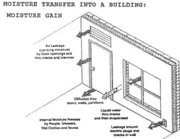
the total cooling Btu. Figure 4 illustrates the energy transfer into a guest room, resulting in a net heat gain. Figure 5 illustrates the moisture transfer modes into a guest room, resulting in a net latent heat gain.
Moisture migrates from a place of high concentration to a place of lower concentration by two methods-diffu-sion through materials and by airflow (infiltration) carrying moisture with it. An air conditioner, by lowering the temperature within the guest room, lowers the partial pressure of moisture as measured by the vapor pressure. Since the vapor pressure is lower in the guest room than the exterior, vapor pressure moisture will flow by dif-fusion toward the room's interior.
The moisture flowing as a result of diffusion is a function of the difference in vapor pressure between the two sides of the supporting walls, the permeability of the construction materials, and the exposed surface area.
The amount of moisture accumulating as a result of airflow is a function of the mass flow rate and the humidity ratio difference of the flow stream and the interior space. In general, air infiltration will have a greater effect on the deterioration of the interior materials than vapor diffusion. The interior space can be the guest room or the wall cavity between the gypsum drywall and the exterior/interior walls.
WALL CAVITIES
The problems associated with "concealed conden-sation" are displayed typically when the gypsum drywall becomes soft and crumbles. This is accompanied by fungal growth, either red, yellow, or black in appearance. There are four ingredients for mold/mildew growth. (1)
Spores, the seed or start of mildew growth, are airborne and everywhere. (2) Food spores feed on a variety of substances, including cellulose, adhesives for wall cover-ings, and vinyl. (3) Temperature spores grow in the same
temperature comfort range as humans. (4) Moisture spores thrive in 70 % to 93 % relative humidity. Below 60 % relative humidity, growth of mildew is greatly retarded.
When moisture is trapped in the wall cavities and condensation takes place, the insulation (if present) deteriorates, the gypsum wall becomes saturated, and crumbling or softening results. There are generally two mechanisms by which water vapor enters the wall cavi-ties. The first mechanism is diffusion of the water vapor resulting from a vapor pressure differential and the "vapor retarder's" permeability. The second mode is by air infiltration resulting from cracks, penetrations for utilities, the effects of bathroom fans when operating, and poor se.als between the through-the-wall air conditioner ' and the surrounding structure.
The amount of water vapor introduced into the wall cavities is the sum of both modes of moisture migration. In general, air infiltration will be the dominant mode for moist air to enter the wall cavities.
In conjunction with the wall cavities and the guest areas, if the building is under negative pressure, openings to the exterior will result in accelerated flow of hot and
?u~d outside air durin~ the summer into the building
mtenor. The result of this inflow of warm air into wall cavities will be saturated insulation and gypsum drywall deterioration. The use of vinyl (which acts as a vapor retarder) on the interior face of the guest room walls can result in serious wall cavity problems. The net result of these deficiencies will be damaged gypsum drywall and mildew.
GUEST ROOMS
The ind~or air comfort envelope (ASHRAE 1989, pp.
8.13-8.16) 1s defined by a range of temperature and
MOISTURE TRANSFER INTO A BUILDING: MOISTURE GAIN
.··
Alfl..e11iuqe (carryu19 moiah.ll'W) by Ooot opeNOg• and
tnruCf'acil.aand~
~
-'*"'"-
cndlainwllll.·
·
MOISTURE GAIN = LEAKAGE + DIFFUSION + INTERNALhumidity levels, which also includes the region associated with mildew growth. Unfortunately, there is some overlap between temperature-humidity levels for mildew growth and for human comfort. Some moisture in the air is necessary for human comfort. Generally, temperature and humidity levels of about 75°F and 40% to 60% in the summer and 70°F and 30% to 50% in winter are recom-mended for human comfort.
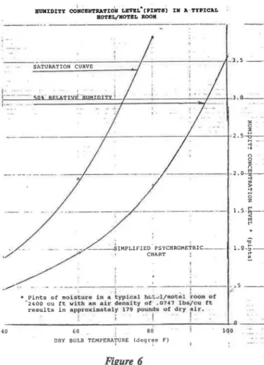
Figure 6 illustrates the humidity concentration level in a typical hotel/motel room. Table 1 illustrates the moisture levels and vapor pressure in a typical hotel/motel room as a fwu:liuu uf th~ ruum's dew-point temperature. Problems that are associated with high humidity levels are (1) corrosion that shows up as rust on iron or steel, (2) odors that linger, (3) moist sheets and drapes, (4) mold growth on exposed surfaces, and (5) associated health issues.
Negative building pressure caused by exhaust (bath-room) fans can cause many air exchanges per hour, and warm, moist air can come through cracks around win-dows, under door seals, and through penetrations (elec-trical, telephone, cable TV) into the guest room's interior and into surrounding wall cavities. Table 2 illustrates typical moisture loads for a hotel/motel room from various activities.
Proper sizing of the air-conditioning unit is essential in order to minimim occupancy discomfort and to mini-mim mold growth. The cooling capacity of an air con-ditioner is the sum of the sensible cooling capabilities and the latent cooling capabilities expressed as Btu/h. The sensible cooling capability is a measure of the air con-ditioner's capability to reduce the dry-bulb temperature. The latent cooling capability is a measure of the air con-ditioner's capability to reduce the moisture (water vapor) from the indoor air. If the air conditioners are shut off during periods of room unoccupancy, moisture buildup in
TABLE 1
Typical Motel Room• Air and Moisture Characteristics at the Saturation Temperature
Saturation Pinta Vapor
Temperature of Moi•ture Pressure
(Of) (in. Hg.I
80 3.84 1.033 75 3.23 .876 70 2.72 .740 65 2.28 .623 60 1.90 .522 55 1.59 .436 50 1.32 .363 45 1.09 .300 40 .90 .248 35 .74 .204 30 .59 .165 25 .47 .130 20 .37 .103 15 .29 .081
"12 ft wide, 25 ft deep, 8 ft high.
•'A typical hotel/motel room of 2.400 ft3 with an air density of .0747
lb/ft3 results in approximately 179 pounds of dry air.
llUllIDITY COHCBllTRATIOlr LEVBL'CPillTSi Ill A TYPICAL BOTEL/KOTBL ROOK
- -
-
-
-·
-
---
-
- -
-
·-
- - - -
-
-
-8 ii . - - -- - -1-2. 0-~..
<:! ::! 0 z··-
-·
--·-·,---
---··--·
.
·--
·
·-
i.s
.
5--I -- - - SIMPLIFIED PSYCHROMETRIC----CHART :..,
...
.;; 1.0-~--.
..
• ...-.. _ - --- -. - - - - - -1 - - - -1:.-.s -40* Pints of molsturo in d yp1c11l ll(.t.J.l/fl\otol. room of "2400 cu ft ~ith an o!r de1U1lty ot .07<7 lbs/cu tt
results in APP[OX1D3taly 179 pound$ oC dty
rlr.
~ i I
60 BO
DRY BULB TEMPERAfURE (degr~e F~
Figure 6
IQD
the room ambient and the furnishings will occur. Re-covery to comfortable room humidity conditions may require an extremely long run time. If the air conditioner is oversimd, the result will be a cold but clammy room. Insufficient run time will result in poor dehumidification performance.
TABLE 2
Typical Motel Room• Interior Moisture Load Maximum Hotel Room Moi•tuTe Loathl:
People
Shower (highest avg. in 4 hours) Misc. (plants/wet clothes/cleaning) Total in room Highest Load in Pints/hour Pints/day .27 (12 h) .20 (4 hi .07 (12 hi .54 3.24 .BO .84 4.88 AveTage Moisture Load (aver 24-hr. period}:
In room
Outside/Exhausted .. Total
0
12 ft wide, 25 ft deep, 8 ft high.
.20 1.58 1.76 Pints/hour 11.4% 88.6% 100.0% 0 0
Good housekeeping can be an important factor in controlling mildew growth. Thorough laundering of the carpets and drapes (to remove entrapped moisture) and cleaning of all surfaces with a fungicide solution on a periodic schedule is important in warm, humid climates.
CONSTRUCTION MOISTURE
Bulle moisture introduced into structural materials during the construction phase or during renovation can result in potential moisture problems. Topping of light-weight concrete over precast floor sections can result in wicking of the water into previously hung drywalls. Under these conditions, if the drywalls are covered with a low-permeance wall covering, mildew may result in a very short period of time.
With the use of stucco-type exterior materials (a relatively breathable construction material), a great deal
of water vapor can be trapped within wall cavities. If the
walls are covered with a low-permeance wall-covering material and condensation occurs, then drywall deteriora-tion can result. Under the influence of the difference in vapor pressure during the cooling season, moisture will migrate toward the room's interior and mildew can form if the interior surfaces are not allowed to "breathe."
During room renovation, the amount of water introduced into resurfacing the drywalls must be allowed to be removed by the latent capacity of the air conditioner or by natural convection (opening the room's windows and doors during low-humidity climatic conditions).
SOLUTIONS
It is accurate to say that no single solution exists for
eliminating or controlling moisture problems in buildings. The dominant mechanism of moisture transport into walls and rooms is usually by air infiltration, and a secondary mechanism is vapor diffusion. Table 3 illustrates the moisture load as a result of air infiltration into a typical
hotel/motel room. It is important to determine the mode
and the amount of moisture migration in order to establish the methods of control. Figures 7 through 9 illustrate, for different wall sections, potential areas where water vapor condensation may result. Figure 10 is a conceptual cross section of a wall designed to minimize water vapor condensation problems.
Based on the test data at the selected Florida sites, the following recommendations or requirements are sug-gested:
In Wall Cavities: Condensation/Deterioration Recommendations or Requirements
• Omit low-permeability wall-covering material from
all interior surfaces (such as vinyl wall covering).
• Exterior building surfaces should have a higher vapor
resistance (low permeability) than interior surfaces.
•
•
•
•
•
•
•
•
•
•
•
•
•
•
•
•
Avoid thermal bridges between the interior (gypsum) walls and the exterior surfaces or the surfaces
en-closing the wall cavities; provide an air space
(mini-mum air infiltration).
Select construction materials and architectural detail-ing with respect to vapor retarder placement and climatic conditions.
Minimize building envelope penetrations from hot, humid outside air, and caulk all penetrations with a material of the proper modulus of elasticity.
Use a vapor retarder on the exterior side of concrete and masonry walls below grade.
Use low-permeability paint or coating on the exterior surface.
Use the highest practical perm-rated paint, avoiding low perm-rated sealants or primers on interior sur-faces.
Provide thermal breaks for metal-framed windows, doors, and furring strips.
Prevent high-humidity air from infiltrating or dif-fusing into all wall cavities.
Circulate conditioned air, not outdoor air, above suspended ceilings.
Avoid foil-backed gypsum board if possible.
In cavity walls with exterior masonry, provide vapor
retarder (sealants) on the warm surface (exterior wall face) in hot and humid climates.
Ensure that air infiltration into the wall cavities is not a function of the operation of bathroom fans, air-conditioning blowers, or related air-circulating systems.
TABLE 3
Typical Motel Room• Interior Moisture Load from Air Infiltration
For a motel room (12 ft wide, 25 ft deep, 8 ft high); Outdoor air 95°F 70% RH (T dp = 84°F) using 1 air change per hour;
Four pints of water will enter the room with the air during the air change;
An air conditioner would have to remove approximately 3
out of the 4 pints of water entering to maintain the room at 75°F with 50% RH ITdp
=
55°F).Air Conditioner Moisture Removal Requirements in Pints per Hour"*
40 cfm outdoor air
Outdoor Dew Point Indoor Dew-point Temperature
90°F 85 80 75 70 65 52 3.95 3.12 2.42 1.82 1.30 0.86 3.72 2.90 2.20 1.59 1.07 0.63
'12 ft wide, 25 ft deep, 8 ft high.
'"AHumes con1tant air density ·.0747 lb/ft3.
3.46 2.64 1.94 1.33 0.82 0.38
HORIZONTAL SECTION OP PARTY WALL TYPICAL GUEST--, ROOM DOOR ..l, METAL DOOR OUTSIDE DECORATIVE FLUTED CONC.BLOCK INSIDE BETWEEN
Cl
POTENTIAL AREAS OF ~OlSTURE CONDENS.\TlON INSIDE Figure 7VERTICAL SECTION OF PLASTER WALL
STUCCO PLAST. ON METAL LATH- - -- -11 OUTSIDE r-- - -3 5/8" METAL STUD 5/8" GYP BOAR 0
VINYL WALL COVER'G
0
0
~ POTE~TIAL AREAS or ~OlSTURE CONDENSHlO~
Figure 9
OUTSIDE
HORIZONTAL SECTION OP MASONRY WALL
r - - - -BRICK
r
3/4" AIR SPACE ,J,r l/2"GYPSUM SHEATHINGINSIDE
~~~YiiiF::::~~f4j:_ BA TT IN SUL AT I ON
?oe::::Jr-111":11'"-3 5/6" METAL STUD
Figure 8
VINYL WALL COVERING 5/B"GYP. BOARD DIRECT GLUED I ! BETWEEN BOARD INSIDE
CONCEPTUAL VERTICAL WALL SECTION POR MINIMUM CONDENSAT!ON
•
•
•
•
Guest room conditions should be controlled to
mini-mize too-low temperatures by introducing limits (mechanical stops or electronic limiters).
Extreme care should be exercised in the selection and installation of piping, ductwork, and insulation in order to isolate cold surfaces from contact with warm, moist air.
There should be seals around conduits, ducting, etc., in order to prevent outdoor air from penetrating into the wall cavity.
Seals should be placed around conductors to prevent
outdoor air from penetrating into the wall cavity.
Inside Guest Rooms: Mold and Mildew Control Recommendations or Requirements Air Infiltration:
•
•
•
•
•
•
•
•
Minimize outside air infiltration by sealing cracks, wall penetrations, and caulking around all exterior seals.
Operate bathroom fans on a demand basis (controlled by the bathroom light switch or on a timer).
Close mechanical damper doors on through-the~wall
air-conditioning units (PT AC); air-conditioning units with automatic dampers should close when the temperature controller is satisfied (a humidistat may
also be required).
Maintain positive indoor pressure relative to ambient conditions in order to minimize outdoor air infiltra-tion into the guest rooms. The soluinfiltra-tion must be compatible with procedures for minimizing smoke spread during fire conditions.
Minimize the time that doors are left open during housekeeping periods.
Condition air in enclosed corridors (halls) that have direct access to guest rooms.
Condition stairways and storage rooms (door louvers) that are adjacent to guest rooms.
Ensure good housekeeping of guest rooms .
Active Temperature and Moisture Control Techniques
•
•
Calculate the sensible and latent cooling loads of the guest rooms, build the rooms according to design, and apply the air-conditioning equipment compatible with these cooling loads (do not oversize). Oversized air conditioning can result in a quick pulldown of the room dry-bulb temperature but with a corresponding high relative humidity.
Operate air conditioners with normal control settings durina the cooling season when the rooms are unoc-cupied or utilize automated room-by-room duty cycling at specific intervals, in combination with high-limit humidistat control.
7--.
.
Evaporator fans should be operated only when theair-conditioning compressor is on.
TEMPERATURE/VAPOR FLOW ANALYSIS
The intermediate temperatures located within a wall assembly can be calculated using steady-state beat transfer methods. The internal wall cavity temperatures are calculated by assuming a linear function dependent upon the thermal resistance (R) (ASHRAE 1989, pp. 22.6-22.9) of the assembly, as well as the overall temperature difference.
In order to minimize condensation within the wall
cavity, the intermediate structural temperatures must remain warmer than the dew-point, or saturation, temper-ature of the outside air. The dew-point tempertemper-ature can be determined based upon the dry-bulb temperature and the
relative humidity. The dew-point temperature can be
highly variable due to daily, as well as hourly, changes in
local climatic conditions. Figure 11 illustrates a cross-sectional view of a typical wall construction considered for analysis.
Determination of the vapor transmission rate
(ASH-RAE 1989, pp. 20.14-20.15) may be determined using a
procedure similar to the heat transmission equations. The vapor flow calculations are less accurate than the heat flow analysis due to the uncertainty associated with the determination of material permeance and the mode of moisture vapor migration. The purpose of a thermal and vapor flow analysis is to determine if condensation of the water vapor introduced by diffusion is possible.
The term ''vapor resistance'' is used to denote the resistance of a material to water vapor transmission and
is expressed mathematically as the reciprocal of
per-meance (M) (ASHRAE 1989, pp. 22.13-22.15). The units
of "perm" are generally expressed as: grains/ft2·h·in.
Hg.
WALL SECTIONAL VIEW FOR ANALYSIS
1/2" GYPSUM DRYWALL
31•"
VF:NEERsic
a
7
(EL,\STO:-tERIC OUTSIDE COATlNGj
8'' CONCRETE BLOCK Figure 11 / Tx,Px - VINYL WALL \""- COVERING 1 \ Tx, Px 1" /\IR SP/\CE 1" POLYSTYRENE
The following environmental data illustrate an average set of conditions during the testin& periods:
Tdb (temperature, dry-bulb) Twb (temperature, wet-bulb)
!_c!E_ (temperature, dew-point) RH (relative humidity) P0 (vapor pressure) Summer 90°F 81°F 78°F 68% .98 in. Hg The following illustrates average interior conditions in a typical guest room:
Summer Tdb 68°F Twb 60°F
~
55°F 63% P, .430 in. HgThe following thermal resistance values (R) and perm (M) are based upon ASHRAE (1989, pp. 22.11-22.14) and from manufacturers' catalogs:
R ft2·h·°F M(Perm)
1
Btu M
Description
Outside Air Film .25 infinite 0 Elastomeric Coating 0 4.4 .23 3/4-in. Stucco Veneer .15 15.0 .07 8-in. Concrete Block .71 2.4 .42 1-in. Polystyrene 3.60 infinite 0 1-in. Air Space (XI .97 infinite 0
Subtotal (Rx) 5.68 (M) .72
1h-in. Gypsum Drywall .45 37.5 .03 Vinyl Wall Covering 0 .5 2.0 Interior Air Film .68 infinite 0 Summation (R,) 6.81 (M,) 2.75 Assume that the plane being considered (X) is at the interface between the gypsum drywall and the 1-in. air gap. The thermal/diffusion drive during the summer would be from the outside toward the inside of the structure. Then where T0 90°F
1j
= 68°F 90 - S.68 (90 - 68)/6.81 TX 71.7°F.Since Tx (71.7°F) is less than Tdp (78°F), there is a potential for condensation at the in~rface between the gypsum drywall and the 1-in. air gap due to the infiltra-tion of warm, moist air. Then
1 p = p - M:c (P -p ) ;c o 1 o I M,
=
.98 - .72 (.98 - .43) 2.1S = .84in. Hg.Since at 71. 7 °F the saturated vapor pressure is approximately . 77 in. Hg, which is lower than the cal-culated pressure at the interface, the lower pressure is
used for the vapor pressure calculations.
The estimated vapor flow to the gypsum drywall is P0 -P:c F,o
=
1 Mx .98- .77 .72 = .29 grains/ft2 •h.
The estimated vapor flow from the gypsum dry wall to the interior is be: F,,_
=
M, Mx F,,._=
.770 - .430 2.75 - .72 = .17 grains/ft2 • h.Water accumulation within the wall assembly would
WO = .29- .17 = .12 grains/ft2 • h .
. The potential rate of water accumulation by diffusion would represent the estimated amount of water vapor available to be condensed within the wall system.
This illustrative analysis indicates that the wall assembly should have a vapor retarder on the warm side of the structure. The vapor retarder must be continuous with all penetrations sealed.
The required vapor resistance can be calculated by letting
x
equal the additional vapor resistance required. Then.12 = .98 - .77.
.12+x
The required x
=
1.03 (permeance) and a resistance (1/x) of . 97, which is equivalent to a gOod polyester film or amulti-layer of elastomeric exterior paint. However, if air infiltrates the wall cavity and the vinyl wall-covering material is in place, mold/mildew may still occur.
It is also possible to reduce the condensation within the wall assembly by removal of the vinyl wall covering, introducing insulation and by increasing the indoor dry-bulb temperature. By removing the vinyl wall covering, the water vapor would be allowed to enter the room to be removed by a running air conditioner.
THE RA TE OF MOISTURE BUILDUP IN GYPSUM DRYWALL CONSTRUCTION DUE TO VAPOR DIFFUSION
The rate of moisture buildup in a gypsum drywall construction can be approximated by assuming a linear moisture buildup. For an initial condition, the represen-tative weight per square foot of gypsum drywall is:
Thickness inches Density lb/ft2 112 5/8 1.8 2.3
The rate of moisture buildup in a gypsum drywall is the difference between the vapor flow rate to the drywall minus the flow from the drywall. From the previous example, the rate of water accumulation is .12 grains/ft2· h, then for a gypsum drywall of 4 ft by 8 ft for 180 days:
.12 x4 x8x24x180
7000
=
2.37 pounds of water.With the assumption that a 112-in.-thick gypsum board has an initial 15 % moisture content, then
1.8 x 4 x 8 x .IS
=
8.64 pounds of water.The final moisture content equals 8.64
+
2.37 = 11.01 lb. The percent increase for 180 days is(11.01 - 8.64) x 100 8.64
=
27.4%.As the drywall accumulates moisture, the structural properties decrease and the growth of molds will become evident. The rate of moisture buildup can increase significantly as a direct result of moist air infiltration. AIR CONDITIONER CHARACTERISTICS
A typical air conditioner can be described as a cold coil located in an air duct. As long as the coil evaporator is cooler than the surrounding air, the coil may satisfy the sensible cooling load. By increasing the size or the
surface area of the coil and/or decreasing the coil temper-ature, the amount of sensible heat removal is increased. To have good moisture removal, the coil temperature must be well below the dew-point temperature of the guest room air, typically 20 to 25°F below the room air temperature. Cold air cannot hold as much moisture as warm air. When air conditioners cool air by moving it over the cooling coils, the refrigerant in the coils can be made cold enough to cause the moisture in the air to condense (tum into a liquid).
The same process occurs when the outside of a drinking glass becomes moist when filled with ice water. The size of a room and the number of people using it help
to determine the air conditioner capacity needed. So do the number, size, and direction of the windows in a room, the wattage of appliances and lights, and the amount of wall insulation.
An air conditioner that has a lower capacity than needed will not keep a room cool. An oversized unit will control the temperature, but it may not remove as much moisture as a correctly sized unit. Such a unit will run only a short time before the temperature falls. It may not even run long enough to remove much moisture from the air.
Air conditioners operate to satisfy the sensible cooling load, not the latent cooling load. The control mechanism is a thermostat that responds to the dry-bulb temperature. The thermostat comes on when the guest room is too
warm, and the air conditioner runs until the indoor temperature is reduced during the cooling cycle.
The amount of latent cooling load removed is depen-dent upon the run time of the air conditioner, the latent cooling capacity of the air conditioner, the evaporator's air temperature, and relative humidity. Figure 12 il-lustrates the latent characteristics of a packaged air conditioner (PTAC). The air conditioner runs until the sensible cooling load is satisfied, but that can still leave an excess latent load. The guest room becomes cooled due to thermostat setting; however, the humidity may still be uncomfortably high.
If an air conditioner is oversized, it will cycle more frequently. Every time it starts, the coil must be cooled below the dew point of the indoor air before it begins to condense water vapor (dehumidify). During start-up, the sensible heat reduction is the greatest; however, dehumidi-fication is the least. With a slightly undersized unit, the system runs a greater percent of the time and dehumidifi-cation may be higher.
ACKNOWLEDGMENT
This project was sponsored by the General Electric Company, Major Appliance Group, Louisville, Kentucky. REFERENCES
"'J.J
8
!:: c8
1.0 f;; "'..
~ ::; .~ "'..
"'
EXPECTED COOLING CHARACTERISTICS OP A •ACllOED 'A/C lJHI'l' AlR COOi.ED .. /C DHU'
RATro C.-001..ltlG CAPACCTY TO COOLINC CAPACl'l'Y AT (EVAPORATOR AIR: eo•r dry bula·~~;,~w£o~c~';.l~ ... )1TlOUS
~ .B'--~~~~-ou_T_oo_oR~DR_Y_B_UL_B_T_EM_P~F.RA_ru~R~~·~~~~~
;:! ~5 15 B ~s 105 115•;
l.O
LATENT CAPACITY Pt:RCt;NT OF TOTAL CAPl\CITY
(OUTDOOR AIR: 95°F dry bul1'. 7~0.f wet bulb)
INDOOR WE'f BULB TEMPERATURE
~,
,,
Figure 12
INOOO~
DRY BULB TEMP
1'1°F
Atlanta: American Society of Heating, Refrigerating, and Air-Conditioning Engineers, Inc.
BIBLIOGRAPHY
1985. Infiltration and air leakage. ASHRAE Transactions 91(2).
ACCA. 1986. Load calculation for residential winter and summer air conditioning. Washington, DC: Air Con-ditioning Contractors of America.
ASHRAE. 1986a. Ventilative cooling in southern residen-ces: A parametric analysis. Thermal Performance of the Exterior Envelope of Buildings Ill. Atlanta: American Society of Heating, Refrigerating, and Air-Conditioning Engineers, Inc.
\:<:.)
ASHRAE. 1986b. Algorithms to predict detailed moisture effects in buildings. Thermal Performance of Exterior Envelopes of Buildings III. Atlanta: American Society of Heating, Refrigerating, and Air-Conditioning Engineers, Inc.
ASHRAE. 1987. Far East Conference on Air Condition-ing in Hot Climates, SCondition-ingapore, September .
ASHRAE/DOE. 1979. Thermal Performance of the Exterior Envelopes of Buildings, Kissimmee, Florida,
December.
ASHRAE/DOE. 1982. Thermal Performance of Exterior Envelopes of Duildings II, Las Vegas, Nevada, December.
ASHRAE/DOE/BTECC. 1985. Thermal Performance of the Exterior Envelopes of Building III, Cleatwater, Florida, December.
CMG. 1987. Dehumidification handbook. Amesbury, MA: Cargocaire Munters Group.
~ndensation potential in high thermal performance walls: Hot/humid/summer climate. United States Depart-ment of Agriculture, Forest Service, Forest Products Laboratory, 1985.
Fairey, P.W., and A.A. Kerestecioglu. 1985. Dynamic modeling of combined thermal and moisture transport in buildings: Effect on cooling loads and space conditions. ASHRAE Transactions 91(2).
FSEC. 1986. Latent and sensible load distributions in conventional and energy efficient residences. January. Cape Canaveral: Florida Solar Energy Center. FSEC. 1988. Whole-building moisture experiments and
data analysis. February. Cape Canaveral: Florida Solar Energy Center.
Moisture conditions in walls and ceilings of a simulated older home during winter. U.S. Department of Agri-culture Fort Service, Forest Products Laboratory, Madison, WI, 1977.
NAHB Research Foundation, Inc. 1979. Insulation manual, home apartments.
NAHB. 1987. Controlling moisture in homes. National Association of Home Builders.
ORNL, UC. 1980. A field study of moisture damage in walls insulated without a vapor barrier. Oak Ridge National Laboratory, Union Carbide, Portland, OR. TROW Inc. 1987. Building science. Brampton, Ontario,