University of Southampton Research Repository
ePrints Soton
Copyright © and Moral Rights for this thesis are retained by the author and/or other copyright owners. A copy can be downloaded for personal non-commercial
research or study, without prior permission or charge. This thesis cannot be
reproduced or quoted extensively from without first obtaining permission in writing from the copyright holder/s. The content must not be changed in any way or sold commercially in any format or medium without the formal permission of the
copyright holders.
When referring to this work, full bibliographic details including the author, title, awarding institution and date of the thesis must be given e.g.
AUTHOR (year of submission) "Full thesis title", University of Southampton, name of the University School or Department, PhD Thesis, pagination
UNIVERSITY OF SOUTHAMPTON
FACULTY OF ENGINEERING AND THE ENVIRONMENT
Aeronautics, Astronautics and Computational Engineering
Plasma Based Jet Actuators for Flow Control
by
Xinfu Luo
Thesis for the degree of Doctor of Philosophy
May 2012
ABSTRACT
A set of plasma based jet actuators were designed for flow control applications. The characteristics of these actuators and their flow control applications were studied experimentally in a low speed wind tunnel.
A dielectric barrier discharge (DBD) based jet actuator is designed, which is made of a covered cavity with two spanwise aligned parallel slots. Two-component particle image velocimetry (PIV) measurements were conducted to determine the effect of actuator in quiescent air and on a canonical zero pressure gradient turbulent boundary layer. It was found that the designed plasma jet actuator produced a transverse jet similar to a continuously blowing jet but with no mass addition into the flow field. The device is different from a traditional alternative blowing-and-suction synthetic jet as the current jet is continuously blown. As such, the DBD based jet actuator is different from either a mass injection blowing jet actuator or a traditional diaphragm based synthetic jet actuator. The impact of the actuation with the designed actuator on the boundary layer characteristics was investigated in detail at different Reynolds numbers.
Circular cylinder wake flow control using a newly designed five-electrode plasma jet actuator is also presented in this thesis. This plasma actuator configuration mounted on the cylinder model can easily produce either a downward or upward jet into the flow around the circular cylinder by simply adjusting the same five electrodes’ electrical circuits. The experiments were performed at Reynolds numbers from 7,000 to 24,000. Wake profile measurements were made to evaluate the modification to the mean and fluctuation velocities in the cylinder wake. The results shown that the cylinder wake flow and the turbulence levels in the wake were modified under the actuations, sectional drag reduction and drag increment were obtained by different actuator actuation directions. The study suggested that this new designed five-electrode actuator can be applied to practical separation suppression or enhancement control by adjusting the plasma actuator electric circuits conveniently.
Contents
Chapter 1 Introduction ... 1
Chapter 2 Literature Review ... 5
2.1 Plasma Actuators ... 5
2.2 Turbulent Boundary Layer Flow and Its Control ... 16
2.3 Flow around Circular Cylinder and Its Control... 22
2.4 Summary ... 25
Chapter 3 Turbulent Boundary Layer Flow Control Using DBD Based Jet Actuators .. 27
3.1 Experimental Apparatus ... 28
3.1.1 Wind Tunnel ... 28
3.1.2 Flat Plate Model ... 31
3.1.3 Plasma Actuator Circuit and Fabrication ... 34
3.1.4 Particle Image Velocimetry ... 36
3.1.5 Error and Uncertainty ... 38
3.2 Results of Jet Blowing from the Downstream Slot ... 39
3.2.1 Jet Actuation without External Flow ... 39
3.2.2 Turbulent Boundary Layer Actuation ... 41
3.3 Results of Jet Blowing from the Upstream Slot ... 50
3.3.1 Jet Actuation without External Flow ... 50
3.3.2 Turbulent Boundary Layer Actuation ... 51
3.4 Summary ... 56
Chapter 4 Circular Cylinder Flow Control Using Plasma Based Jet Actuators... 59
4.1 Experimental Setup ... 59
4.1.1 Wind Tunnel Facility ... 59
4.1.2 PIV Setup ... 60
4.1.3 Error and Uncertainty ... 61
4.1.4 Plasma Based Jet Actuators Design ... 61
4.2 Application of Plasma Based Jet Actuators to a Circular Cylinder Model ... 67
4.3 Experimental Results for Downward Plasma Actuations ... 71
4.3.1 Results of a SD based Downward Actuation ... 71
4.3.2 Results of Plasma Parameter Studies ... 83
4.3.3 Results of an AC+DC Based Downward Actuation ... 87
4.4.1 Results of an Upward AC+DC Actuation ... 89
4.4.2 Results of a SD Based Upward Actuation ... 100
4.5 Summary ... 102
Chapter 5 Conclusion and Future Work ... 103
5.1 Conclusions ... 103
5.2 Recommendations for Future Work ... 105
List of figures
Figure 2.1: A typical classification of flow control actuators . ... 5
Figure 2.2: DC discharge plasma actuator. ... 9
Figure 2.3: A typical DBD actuator. ... 10
Figure 2.4: A S3DBD actuator . ... 11
Figure 2.5: Velocity component of backward flow . ... 11
Figure 2.6: Electric wind velocity for multi-DBD array . ... 12
Figure 2.7: Schematic of a PSJA . ... 13
Figure 2.8: An L-PSJA actuator. ... 13
Figure 2.9: Configuration of a three electrodes plasma actuator. ... 14
Figure 2.10: A three-electrode plasma actuator without DC. ... 14
Figure 2.11: A three-electrode plasma actuator with DC<0. ... 15
Figure 2.12: A three-electrode plasma actuator with DC>0. ... 15
Figure 2.13: A SD plasma actuator configuration. ... 16
Figure 2.14: Jets driven by (a) steady and (b) stroboscopic illumination ... 20
Figure 2.15: A piezoelectric synthetic jet actuator ... 21
Figure 2.16: Flow regimes of a circular cylinder. ... 22
Figure 3.1: Schematic of the wind tunnel general assembly. ... 28
Figure 3.2: Traverse system in the wind tunnel. ... 29
Figure 3.3: Hot-wire measurement system. ... 30
Figure 3.4: A typical hot-wire calibration curve. ... 30
Figure 3.5: Wind tunnel background turbulence level. ... 31
Figure 3.6: Boundary layer development flat plate. ... 32
Figure 3.7: Static pressure distribution along the flat plate. ... 33
Figure 3.8: Characteristics of the flat plate boundary layer. ... 33
Figure 3.9: Plasma power supply circuit. ... 34
Figure 3.10: Photo of a single DBD actuator. ... 35
Figure 3.11: Induced velocity profiles by a DBD in quiescent air... 36
Figure 3.12: A schematic of the PIV system configuration (side view). ... 37
Figure 3.13: Comparison of different measurement methods ( =10m/s). ... 37
Figure 3.14: Boundary layer development flat plate and actuator. ... 39
Figure 3.15: Actuator induced velocity field in ambient air. ... 40
Figure 3.17: PIV measurement at =5 m/s, =18.5 kV. ... 43
Figure 3.18: Boundary layer characteristics at different streamwise positions ( =5 m/s, =18.5 kV). ... 44
Figure 3.19: PIV measurement at =3 m/s, =18.5 kV. ... 45
Figure 3.20: PIV measurement at =10 m/s, =18.5 kV. ... 46
Figure 3.21: Boundary layer characteristics at =3 m/s, =18.5 kV. ... 47
Figure 3.22: Boundary layer characteristics at =5 m/s, =18.5 kV. ... 47
Figure 3.23: Boundary layer characteristics at =10 m/s, =18.5 kV. ... 47
Figure 3.24: Effects of distance between the two slots of the actuator. ... 49
Figure 3.25: Upstream blowing plasma based jet actuator (sketch not to scale). ... 50
Figure 3.26: Upstream blowing actuator induced velocity field in ambient air. ... 51
Figure 3.27: Comparison of mean velocity flow field ( =3 m/s, =18.5 kV). ... 52
Figure 3.28: Comparison of mean vorticity flow field ( =3 m/s, =18.5 kV). ... 52
Figure 3.29: Comparison of mean velocity profiles ( =3 m/s, =18.5 kV). ... 53
Figure 3.30: Comparison of turbulent intensity profiles ( =3 m/s, =18.5 kV). ... 53
Figure 3.31: Effects of upstream slot blowing at =3 m/s. ... 54
Figure 3.32: Effects of upstream slot blowing at =5m/s. ... 55
Figure 3.33: Effects of upstream slot blowing at =10 m/s. ... 55
Figure 3.34: Effects of distance between the two slots of the actuator. ... 56
Figure 4.1: Cylinder model in the wind tunnel. ... 60
Figure 4.2: Arrangement of PIV measurement (top view). ... 60
Figure 4.3: A high DC voltage power supply ... 61
Figure 4.4: An AC+DC plasma actuator. ... 62
Figure 4.5: A SD plasma actuator. ... 63
Figure 4.6: The measurement of a SD plasma actuator induced velocity. ... 64
Figure 4.7: Induced velocity profiles by a single SD actuator in quiescent air. ... 65
Figure 4.8: A five-electrode actuator configuration. ... 66
Figure 4.9: Discharge of a five-electrode actuator. ... 66
Figure 4.10: Induced velocity field in ambient air of a five-electrode actuator. ... 66
Figure 4.11: Schematic of a five-electrode actuator on a cylinder model. ... 67
Figure 4.12: Induced velocity field in ambient air of a downward actuation. ... 68
Figure 4.13: A SD based upward five-electrode actuator configuration. ... 69
Figure 4.15: Velocity field at = 5 m/s (SD, =17.5 kV, DC=-10 kV)... 72
Figure 4.16: Velocity field at = 10 m/s (SD, =17.5 kV, DC=-10 kV). ... 72
Figure 4.17: Turbulence intensity at =3 m/s (SD, =17.5 kV, DC=-10 kV). ... 73
Figure 4.18: Turbulence intensity at =5 m/s (SD, =17.5 kV, DC=-10 kV). ... 73
Figure 4.19: Turbulence intensity at =10 m/s (SD, =17.5 kV, DC=-10 kV). ... 74
Figure 4.20: Wake streamwise mean velocity profiles (X/D=2, =5 m/s). ... 75
Figure 4.21: Wake streamwise mean velocity profiles (X/D=3, =5 m/s). ... 75
Figure 4.22: Wake streamwise mean velocity profiles (X/D=4, =5 m/s). ... 75
Figure 4.23: Wake streamwise turbulence intensity profiles (X/D=2, =5 m/s). ... 76
Figure 4.24: Wake streamwise turbulence intensity profiles (X/D=3, =5 m/s). ... 76
Figure 4.25: Wake streamwise turbulence intensity profiles (X/D=4, =5 m/s). ... 76
Figure 4.26: Wake transverse mean velocity profiles (X/D=2, =5 m/s). ... 77
Figure 4.27: Wake transverse mean velocity profiles (X/D=3, =5 m/s). ... 78
Figure 4.28: Wake transverse mean velocity profiles (X/D=4, =5 m/s). ... 78
Figure 4.29: Wake transverse turbulence intensity profiles (X/D=2, =5 m/s). ... 79
Figure 4.30: Wake transverse turbulence intensity profiles (X/D=3, =5 m/s). ... 79
Figure 4.31: Wake transverse turbulence intensity profiles (X/D=4, =5 m/s). ... 79
Figure 4.32: Comparison of cylinder drag coefficients (SD, =5 m/s). ... 80
Figure 4.33: Wake streamwise velocity profiles at =7,000 (X/D=2.5). ... 81
Figure 4.34: Wake streamwise velocity profiles at =12,000 (X/D=2.5). ... 81
Figure 4.35: Wake streamwise velocity profiles at =24,000 (X/D=2.5). ... 81
Figure 4.36: Wake streamwise turbulence intensity at =7,000 (X/D=2.5). ... 82
Figure 4.37: Wake streamwise turbulence intensity at =12,000 (X/D=2.5). ... 83
Figure 4.38: Wake streamwise turbulence intensity at =24,000 (X/D=2.5). ... 83
Figure 4.39: Comparison of streamwise velocity at different applied AC voltages. ... 84
Figure 4.40: Comparison of transverse velocity at different applied AC voltages. ... 84
Figure 4.41: Comparison of streamwise velocity at different applied DC voltages. ... 85
Figure 4.42: Comparison of transverse velocity at different applied DC. ... 86
Figure 4.43: Schematic of a SD based downward actuator configuration (DC>0). ... 86
Figure 4.44: Comparison of streamwise velocity with different high DC polarity. ... 87
Figure 4.45: Comparison of transverse velocity with different high DC polarity. ... 87
Figure 4.47: Comparison of SD and AC+DC based downward actuations (streamwise
velocities). ... 88
Figure 4.48: Comparison of SD and AC+DC based downward actuations (transverse velocities). ... 89
Figure 4.49: Schematic of an AC+DC based upward actuator configuration. ... 90
Figure 4.50: Velocity field at =3 m/s (AC+DC, =17.5 kV, DC=-10 kV). ... 90
Figure 4.51: Velocity field at =5 m/s (AC+DC, =17.5 kV, DC=-10 kV). ... 91
Figure 4.52: Velocity field at =10 m/s (AC+DC, =17.5 kV, DC=-10 kV). ... 91
Figure 4.53: Turbulence intensity contours at =3 m/s (AC+DC, =17.5 kV, DC =-10 kV). ... 92
Figure 4.54: Turbulence intensity contours at =5 m/s (AC+DC, =17.5 kV, DC =-10 kV). ... 92
Figure 4.55: Turbulence intensity contours at =10 m/s (AC+DC, =17.5 kV, DC =-10 kV). ... 93
Figure 4.56: Wake streamwise velocity profile (AC+DC, X/D=2, =5 m/s). ... 94
Figure 4.57: Wake streamwise velocity profile (AC+DC, X/D=3, =5 m/s). ... 94
Figure 4.58: Wake streamwise velocity profile (AC+DC, X/D=4, =5 m/s). ... 94
Figure 4.59: Wake streamwise turbulence intensity (AC+DC, X/D=2, =5 m/s). ... 95
Figure 4.60: Wake streamwise turbulence intensity (AC+DC, X/D=3, =5 m/s). ... 95
Figure 4.61: Wake streamwise turbulence intensity (AC+DC, X/D=4, =5 m/s). ... 95
Figure 4.62: Wake transverse velocities (AC+DC, X/D=2, =5 m/s). ... 96
Figure 4.63: Wake transverse velocities (AC+DC, X/D=3, =5 m/s). ... 97
Figure 4.64: Wake transverse velocities (AC+DC, X/D=4, =5 m/s). ... 97
Figure 4.65: Comparison of cylinder drag coefficients (AC+DC, =5 m/s)... 98
Figure 4.66: Wake streamwise velocities at =7,000 (AC+DC, X/D=2.5). ... 99
Figure 4.67: Wake streamwise velocities at =12,000 (AC+DC, X/D=2.5). ... 99
Figure 4.68: Wake streamwise velocities at =24,000 (AC+DC, X/D=2.5). ... 100
Figure 4.69: Comparison of AC+DC and SD based upward actuations (streamwise velocities). ... 101
Figure 4.70: Comparison of AC+DC and SD based upward actuations (transverse velocities). ... 101
List of tables
Table 3.1: Boundary layer characteristics at different applied voltages (ΔX=20mm)….42
Table 3.2: Boundary layer characteristics along the flat plate..………...44 Table 3.3: Effects at different Reynolds number……….48 Table 4.1: Experimental matrix ….……….69
DECLARATION OF AUTHORSHIP
I, Xinfu Luodeclare that the thesis entitled
Plasma Based Jet Actuators for Flow Control
and the work presented in the thesis are both my own, and have been generated by me as the result of my own original research. I confirm that:
this work was done wholly or mainly while in candidature for a research degree at
this University;
where any part of this thesis has previously been submitted for a degree or any other
qualification at this University or any other institution, this has been clearly stated;
where I have consulted the published work of others, this is always clearly
attributed;
where I have quoted from the work of others, the source is always given. With the
exception of such quotations, this thesis is entirely my own work;
I have acknowledged all main sources of help;
where the thesis is based on work done by myself jointly with others, I have made
clear exactly what was done by others and what I have contributed myself;
parts of this work have been published as:
Luo, X. and Zhang, X., 2011, “Dielectric barrier discharge based jet actuator for
flow control,” 41st AIAA Fluid Dynamics Conference and Exhibit, AIAA paper
2011-3988.
Zhang, X., Luo, X. and Chen, P., 2011, “Airfoil flow control using plasma
actuation and Coanda effect ,” 29th AIAA Applied Aerodynamics Conference, AIAA
paper 2011-3516.
Peers, E., Huang, X., and Luo, X., 2009, “A numerical model of plasma-actuator
effects in flow-induced noise control,” IEEE transactions on plasma, Vol. 37, No. 11,
pp. 2250-2256.
Signed:
Acknowledgements
There are many individuals that I would like to thank for providing me with support during my period of Ph.D. study. First of all, I would like to express my sincere gratitude to my supervisor, Professor Xin Zhang, for his guidance, encouragement and patience throughout the research period. He has shown me what a scientist should do and how to become a researcher. I would also like to thank my advisor, Dr. Zhiwei Hu, for his support and sharing his knowledge and experience.
I am very grateful to Dr. Xun Huang and Dr. Yong Li for helping me learn experimental techniques and for assisting me with the experiments. I would like to thank all other colleagues in the AFM Group for their warm friendship and support during my Ph.D. study. I would also like to thank my old friends in China, for their constant encouragement through all these years.
I would like to acknowledge that the research leading to these results has received funding from the European Community's Seventh Framework Programme FP7/2007-2013 under Grant Agreement No:234201.
Finally, I would like to show my greatest appreciation to my family and especially to my dear wife, Lan Wei, in particularly for her encouragement and taking care of our lovely young daughter over these years. Without her support and hard work, this work could not have been completed.
Definitions and abbreviations
Nomenclature
b1/2 wake half-width, m
cd drag coefficient
D distance between actuator two slots centerline or cylinder diameter, m
H shape factor
P static pressure, Pa
Patm atmospheric pressure, Pa
ΔP relative static pressure (P-Patm), Pa
Re Reynolds number
Reynolds number based on the cylinder diameter
U mean streamwise velocity, m/s
ΔU streamwise velocity defection, m/s
ΔUmax maximum of velocity reduction, m/s
u streamwise velocity fluctuations, m/s
RMS of streamwise velocity, m/s
freestream velocity, m/s friction velocity, m/s
normalized streamwise mean velocity (U/ uτ)
v vertical velocity fluctuations, m/s
peak-to-peak voltage, V
Vel velocity magnitude, m/s
W mean transverse velocity, m/s
w transverse velocity fluctuations, m/s
RMS of transverse velocity, m/s
X streamwise coordinate, m
ΔX streamwise distance from the actuator downstream slot centerline in, m
Y vertical coordinate, m
normalized wall normal coordinate ⁄
Z transverse coordinate, m
Greek symbols
boundary layer thickness
boundary layer displacement thickness boundary layer momentum thickness
Abbreviations
AC alternative current
DC direct current
AC+DC a plasma actuator configuration combined with AC and DC power supplies
DBD dielectric barrier discharge
IGBT insulated gate bipolar transistor
PIV particle image velocimetry
RMS root mean square
SD sliding discharge
TBL turbulent boundary layer
Chapter 1
Introduction
Plasma actuators are relatively new devices for flow control. A dielectric barrier discharge (DBD) actuator is a commonly used type of plasma actuators. A single DBD actuator consists of two electrodes separated by a dielectric, where the upper electrode is usually exposed to the flow and the lower electrode is insulated. The actuator is driven by a high frequency (hundreds Hz to tens kilo-Hz) AC voltage of several thousand volts. The electrodes can be fabricated from metal tapes or wires, and dielectric can made from Kapton, glass, ceramics, rubber and other materials. The actuators are inherently robust, relatively easy and inexpensive for practical flow control applications [1]. However they also suffer from a lack of control authority.
There are a number of flow control methods using a jet issued into an oncoming stream in the transverse direction (either with a net mass flow or with a zero net mass flux). Zero net mass flux jets (or synthetic jets) are formed from the working fluid of the system in which they are applied, and have been widely used as active flow control devices. These types of devices commonly use an oscillating diaphragm on the floor of a cavity to produce the required jets. The actuator units usually are flush mounted on the aerodynamic surface of interest. The diaphragm is driven periodically and hence the fluid is alternatively ejected from or sucked into the cavity at a certain frequency. A comprehensive review of the synthetic jets was given by Glezer and Amitay [2].
The two active flow control devices mentioned above operate on fundamentally different mechanisms. The work present here aims to investigate a new concept of constructing a flow control device that combines the features of both plasma actuators and synthetic jets. In order to produce a vertical plasma jet just using a single DBD, a normal DBD actuator is installed into a cavity and aligned perpendicular to the
freestream. The jet velocity and actuation frequency can be controlled through the plasma actuation parameter adjustment. In this study, the plasma induced ionic wind injects into the flow field through a spanwise oriented rectangular slot. As the air in the cavity is ionized by the plasma actuation, a constant air supply is needed and to this purpose an air supply slot with the same size is integrated into the system to supply fresh air to the cavity.
In this work, the above mentioned DBD based plasma jet actuator was designed and used to control a ZPG TBL flow. One objective of this research is to investigate the physical mechanism associated with TBL control using the new DBD based plasma jet actuators and discern their applications in other flow control applications such as airfoil, bluff body and others.
On the other hand, bluff body wakes affect the performance of many air vehicles, thus motivating significant research efforts into modifications of the unexpected wake effects. For this reason, another objective of the work presented in this thesis is to develop and implement plasma based jet actuators for the control of a circular cylinder wake. Bluff body wake flow is usually characterized by high level of unsteadiness, large regions of separated flow, and highly fluctuating pressures. Problems resulting from bluff body wakes including high drag, noise emissions, and distorted optimal path of separated shear layers. The high drag penalty due to separated flows is a significant problem for commercial and military vehicles. Another relevant issue is that the aircraft noise can be associated with vortex shedding from landing gear structures and the level could be quite high. The representative shapes on a landing gear are bluff bodies. Those situations require regularization of the separated flow. Several combinations of the designed plasma actuators are implemented in this research.
Many studies have been conducted to control the flow behavior using the downward jet for the main flow at different Reynolds numbers. However, less study has been conducted using an upward jet. With this background, the aim of this study was to investigate the wake characteristics behind a circular cylinder using the downward and upward plasma based jet actuators under different Reynolds number. The downward and upward jets to the main flow direction were induced by changing electrode
arrangements. The flow behaviors of the wake generated by the introduction of the downward and upward plasma based jet actuators were investigated using PIV.
This thesis describes the experimental works performed to control the TBL and circular cylinder flows using plasma based jet actuators. The thesis is structured into several chapters. Chapter 2 provides a review of the fundamental mechanisms of the boundary layer and cylinder flows and the existing methods for their flow control. Relevant plasma actuators were also introduced in this chapter. Chapter 3 is concerned with the experimental results of the TBL flow control by using a newly designed plasma jet actuator. The facilities and the experimental setup used for the research including the design of the wind tunnel model and the plasma actuator system are also presented. Chapter 4 is devoted to the experimental results obtained from wind tunnel testing on circular cylinder flow control using different combination plasma actuators. The baseline flow and wake fields with and without plasma actuations of a circular cylinder are discussed. Conclusions and a discussion on future work are presented in Chapter 5.
Chapter 2
Literature Review
In this chapter, works related to plasma actuators and their applications, TBL flow and its control, circular cylinder flow and its control are reviewed.
2.1 Plasma Actuators
There are various types of actuators for flow control applications, and these can be
classified in a number of ways. Cattafesta III and Sheplak [3] classified them as
illustrated in Figure 2.1, which classified the actuators based on function as fluidic, moving object/surface, plasma and others.
Their review provided a framework for the discussion of actuator specifications, characteristics, selection, design, and classification for aeronautical applications and also highlighted the strengths and inevitable drawbacks of each and potential future research directions. Because the work in this thesis is based on plasma actuators, the relevant topic on plasma actuators is discussed separately here.
Plasma is formed by particles which break down into positive and negative ions under sufficient energy. A simple plasma actuator consists of two electrodes powered by high voltage (AC or/ and DC). When a high enough voltage (kilo-volts) is applied, cold plasma appears between the electrodes. The discharge is based on the mechanism of electron avalanche, and its regime is a function of voltage-current. These discharges can be achieved with high voltage from a few kilo-Volts to several tens of kilo-Volts, frequency from 50 Hz to 50 kHz, and current from a few µA to a few mA.
A detailed discussion of the main characteristics of plasma can be found in Roth’s [4]. Collision ions and neutral molecules in electrode gap form electric wind, corona or/and ionic wind, and flow between the electrodes. An equation for velocity of electric wind is given by:
= √
where is geometrical constant, is the ion mobility, is the time-average current and
is gas density. The velocity of ions is:
= (2.2)
Where is intensity of electric field. The velocity of ions can usually reach hundreds or
thousands meters per second, but the electric wind velocity is about a few meters per
second. A parametric study performed by Forte et al [5] in order to increase the velocity
of the ionic wind induced by DBD actuators. Their results indicated that an optimization of geometrical and electrical parameters can obtain a time-averaged ionic wind velocity up to 8 m/s at 0.5 mm from the wall.
A surface corona discharge basically uses two wire-electrodes embedded on the surface (not covered). The anode diameter is less than the cathode’s. When the electric field strength is greater than the breakdown energy of the surrounding neutral particles, an electrical discharge brought on by the ionization of air surrounding a conductor.
Increasing of onset voltage at a certain gap between the electrodes, the discharge regime will turn from a spot regime to a streamer regime and a thin sheet of blue ionized air will appear between the electrodes. The glow discharge is obtained with higher voltage; there is no thin sheet of blue ionized air between both electrodes but only a set of adjacent luminescent spots around both electrodes. This is usually called a typical corona. When the voltage increases further, filament will then occur. Surface corona discharge is sensitive to humidity, pressure, temperature, electrode geometry and other environmental conditions. The velocity of electric wind increases with applied current.
The measured maximum velocity is at about 1mm above the surface [6].
In order to prevent the transition to corona/sparks, a dielectric barrier is placed between electrodes and AC frequencies from 50 Hz to 500 kHz are applied instead of using DC voltage input. The most typical actuator is surface dielectric barrier discharging (DBD), which was invented by Roth [7] in 1998. A simple DBD actuator consists of a dielectric with two electrodes placed on both sides. One electrode is excited by an AC high voltage and the other is grounded. When the voltage reaches the ignition value, plasma appears on both sides and induces electric wind at the same time. In practical use, the grounded electrode usually is encapsulated. Then there is no electric wind on the bottom side. Many detailed works [8,9,10,11] have been reported on the physics of the plasma. Electrical and mechanical properties are strongly dependent on various parameters such as electrode width, electrode gap, dielectric material and thickness, high voltage value and frequency and so on. Generally speaking, a body force is generated by the collisions of the accelerated ions with the neutral air molecules. Due to the force production mechanism, the force is limited to a small region close to the gap between the anodes and the cathodes. This force acts on the air to accelerate and hence change its velocity. The force will create a wall jet by accelerating the air tangentially to the wall in quiescent medium and leads to a pressure drop above the electrodes. The force depends on the operating voltage of the actuator. The body force is proportional to 3.5 power of the applied high AC voltage [12,13].
Moreau [14] summarized the velocity profiles of their DBD actuators as below:
the velocity induced by the grounded electrode (when it is not encapsulated) is
slightly smaller than the velocity induced by the high voltage electrode;
the air exposed electrode, meaning that the discharge induces a depression towards the wall;
the maximum velocity is always reached at the limit of the plasma extension,
usually placed at the downstream edge of the grounded electrode;
at low frequency (from 300 to 700 Hz), and up to 20 kV, the maximum velocity
which is usually at about 0.5mm above the wall, increases linearly with the applied voltage.
As to the induced net force, the main findings are [14]:
the waveform is of great importance in the net force. In fact, the positive saw
tooth waveform produces the greatest net force for a given input power;
the optimum frequency is 5 kHz (under their conditions);
thicker dielectric configurations are generally able to produce higher maximum
net forces because the dielectric is able to withstand higher currents;
net force is proportional to the applied frequency;
the force induced by a positive pulse is greater than the one induced by a
negative pulse.
Plasma actuators are relatively new devices for flow control that have several obvious advantages but also disadvantages. Some advantages were summarized by Grundmann [15] as following:
No moving parts.
Very short response time. It is in the order of 10 to 100 μs depending on the
operating frequency.
Operable in a wide frequency range. The operating frequency can be increased
up to 100 kHz,
Simple integration into an aerodynamic model. The plasma actuator consists of
just two foil-like electrodes and an insulation film in between.
Low system mass. The actuator itself is very light; the main weight comes from
the power supplies for the actuators.
The main disadvantage is the low efficiency of energy conversion and high voltage application. These actuators may also modify the gas properties near the wall (such as density and temperature). But overall it is a very promising device for flow control
applications. Consequently, plasma actuators are now widely used in flow controls, especially in boundary layer flow control and relevant areas.
Depending on different discharge, many plasma actuators have been developed for practical flow control. Some actuators for flow control application are listed below:
Surface corona discharge actuator. Corona discharge actuators use an anode and a cathode mounted in the working fluid. The anode emits positive ions that travel to and bombard the cathode surface. A typical configuration of DC plasma actuator is shown in Figure 2.2.
Anode Cathode Dielectric
Figure 2.2: DC discharge plasma actuator.
These kinds of actuators have been used for a number of fluid dynamic applications, which showed their abilities for drag reduction [16,17]. Control of low velocity airflow along a flat plate by a DC surface corona discharge was investigated by Moreau et al [18]. A significant drag reduction has been achieved for velocities up to 25 m/s. The maximum drag reduction is about 30% at 1mm downstream of the cathode and 35% at the trailing edge (70mm downstream of the cathode). The drag decreases with the applied current.
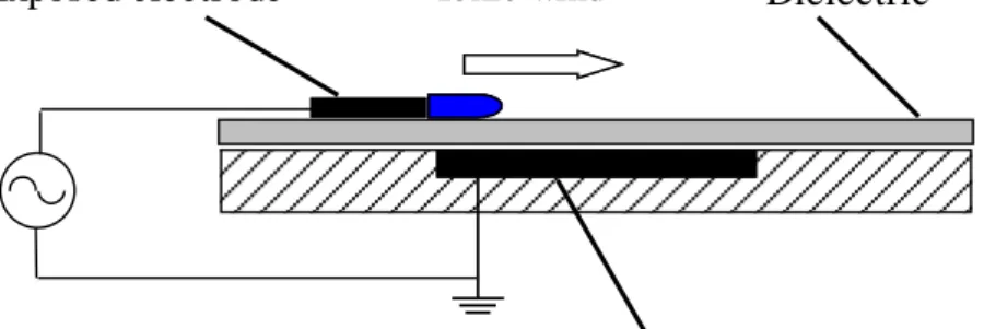
Surface DBD actuators. A single DBD consists of two electrodes separated by a dielectric, while the upper electrode is usually exposed to the flow and the lower electrode is insulated. This type of actuator is the most commonly used plasma actuator, as sketched in Figure 2.3.
Encapsulated electrode
Exposed electrode Ionic wind Dielectric
Figure 2.3: A typical DBD actuator.
This actuator is driven by a high frequency (hundreds Hertz to tens kilo-Hertz) AC-voltage of several thousand volts. The electrodes can be fabricated from metal tape or wire, dielectric can made from Kapton, glass, ceramics, rubber and other materials, making them inherently robust, relatively easy and inexpensive for practical flow control applications. Roth [37] first demonstrated a variety of flow control applications in boundary layers. Streamwise and spanwise oriented actuators were used to alter the velocity profiles of boundary layers at different velocities. Drag reduction and increment were observed on a panel downstream of the actuator, depending on the actuator’s orientation. Investigations for TBL drag reduction were performed by Jukes et al. [19,20], they used opposing pairs of asymmetric surface AC glow discharge plasma electrodes to produce spanwise flow oscillation in the near-wall region of a TBL. In their study, the electrode sheet was affixed to a heat sink flush mounted 1.9m from the leading edge of a 3m long flat plate, over which a TBL was developed. The freestream speed was 1.8m/s and the boundary layer thickness is approximately 70mm at the measurement position. The plasma jet velocity was around 1 m/s and the frequency of the generated velocity oscillation was 21 Hz. A 22% drag reduction was reported. Investigations of different plasma actuators for boundary layer flow control have also been done by others [21,22].
Apart from using a single actuator, actuators can also be implemented as arrays [37]. The actuators in an array can be driven with voltages of the same phase or with a phase shift between them. A phase shift driving causes an electrostatic wave to move along the surface and results in higher wall-jet velocities than with actuators in phase. Roth also invented actuators combine peristaltic and paraelectric effect and the induced
Usually, the plasma induced flow velocity is limited and has an asymptotic behavior
with increasing operating voltage [23], so the applications are normally restricted to
small scale. The above mentioned DBD arrays, energized by zero-phase delayed or phase- shifted high voltages can be used in larger scale. However, the mutual interaction between successive discharges introduces negative effects to the standard multi-DBD actuators as well. Benard et al [24] newly designed an electrode for large-scale flow control applications. It replaces each single two-electrode DBD (S2DBD) by a three-electrode DBD (S3DBD) where the third three-electrode acts as a shield between the two successive DBDs (Figure 2.4).
Figure 2.4: A S3DBD actuator [24].
Figure 2.5: Velocity component of backward flow [24].
Experimental measurements results shown that the S3DBD design can reduce the backward flow by 65% (Figure 2.5).
Because a S3DBD can eliminate the backward flow, it may induce a larger and steadier plasma flow. Their results showed that the interaction between the electrodes, although not fully cancelled, is strongly reduced. This new DBD design conduces to a nearly constant plasma speed over the whole actuation surface (Figure 2.6). From a practical point of view, this design is suitable for large-scale and stable actuation applications.
Figure 2.6: Electric wind velocity for multi-DBD array [24].
Plasma synthetic jet actuators. A plasma actuator design consisting of an annular electrode array, the Plasma Synthetic Jet Actuator (PSJA), was investigated by Santhanakrishnan [25]. This particular plasma induced flow is in the form of a vertical synthetic jet (Figure 2.7). This configuration is basically still a DBD actuator, but its induced flow alignment is perpendicular to the surface compare to a tangential wind of a traditional DBD, we therefore discuss it separately. If the jet is induced by using two rectangular-strip exposed electrodes and one embedded electrode (Figure 2.8), it is usually called a linear plasma synthetic jet actuator (L-PSJA). A PSJA configuration can be easily reversed to act as a suction device by exchange the electrodes.
a) top view and cross section b) Plasma ring created on actuation Figure 2.7: Schematic of a PSJA [22].
Encapsulated electrode (2)
Exposed electrode (1) Ionic wind Exposed electrode (3) Dielectric
Figure 2.8: An L-PSJA actuator.
The two actuators were observed to affect the flat plate boundary layer flow field in different manners. The PSJA was observed to interact with a cross flow in a similar manner as a conventional jet. The interaction of the L-PSJA with a cross flow results in the formation of a cross stream vortex downstream of the plasma region, similar to a single DBD actuator. The effectiveness of the plasma synthetic jet in penetrating the mean flow was found to decrease with increase in Reynolds number.
Three-electrode actuators. More recently, a new group of plasma actuators consisting in three electrodes devices has been developed [26] (Figure 2.9).
Encapsulated electrode (2)
Exposed electrode (1) Exposed electrode (3) Dielectric
Figure 2.9: Configuration of a three electrodes plasma actuator.
Two upper electrodes (1) and (3) are flush mounted on the air-exposed surface, and a lower electrode (2) is placed on the opposite side of the insulating surface. The concept is to utilize the AC DBD to weakly ionize the air, and then to superpose a DC potential that establishes a corona discharge between spatially separated electrodes. The DC component induces the sliding discharge.
With different AC and DC component combination circuits, some special plasma can be induced. If the first upper electrode (1) is at an AC voltage and the electrodes (2) and (3) are grounded, a typical surface dielectric barrier discharge is formed between electrodes (1) and (3), the actuator works like a conventional DBD actuator (Figure 2.10).
Encapsulated electrode (2)
Exposed electrode (1) Ionic wind Exposed electrode (3) Dielectric
Figure 2.10: A three-electrode plasma actuator without DC.
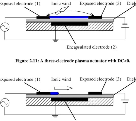
On the other hand when the electrode (1) is at an AC voltage and the electrode (3) is applied to a high enough DC voltage with electrode (2) grounded, different discharges will be induced depending on the polarity of the DC voltage. A plasma sheet which occupies the whole electrode gap is produced when DC < 0. The direction of the
actuator induced electric wind depends on the applied AC voltage. By varying the AC voltage value one can make the global plume like flow direction and span angles almost
lying in the range 0-180o referred to the dielectric surface (Figure 2.11). The discharge
looks like a normal DBD, but with stronger actuation when DC > 0 (Figure 2.12). Both discharges were as stable as the corresponding DBD [27, 28, 29].
Encapsulated electrode (2)
Exposed electrode (1) Ionic wind Exposed electrode (3) Dielectric
Figure 2.11: A three-electrode plasma actuator with DC<0.
Encapsulated electrode (2)
Exposed electrode (1) Ionic wind Exposed electrode (3) Dielectric
Figure 2.12: A three-electrode plasma actuator with DC>0.
The drag reduction in a circular cylinder was explored by Sosa et al [30] using these three-electrode plasma actuators. The results indicated that these actuators can reduce the drag coefficient by up to 25% with respect to the base flow drag coefficient. The three three-electrode plasma configurations mentioned above will be called as AC+DC actuation
Another design was made by Thomas et al [31]. In this case, the electrode (2) is connected to an AC voltage while a DC voltage (either positive or negative) is applied
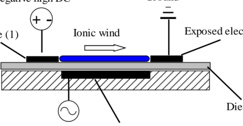
to electrode (1) and the electrode (3) grounded (Figure 2.13). When the actuator is operating only with the AC input on, it works like two DBDs and very weak plasma can be seen near the edges of the two exposed electrodes. However, the addition of the DC induced visible plasma can extend the whole space between electrodes (1) and (3). The induced electric wind direction depends on the polarity of the input DC voltage. Sliding Discharge (SD) will be used to define those kinds of configurations in this thesis.
Ionic wind
High AC Encapsulated electrode (2)
Exposed electrode (1)
Dielectric Exposed electrode (3)
+
-Negative high DC Ground
Figure 2.13: A SD plasma actuator configuration.
Roupassov et al designed a new DBD based actuator driven with repetitive nanosecond-scale pulse signal [32,33,34,35]. The rapid discharge (5–50 ns) promotes rapid gas heating that creates localized shock waves with little discernible electric wind, suggesting that these are no longer cold plasmas. This short-pulse DBD may substantially improve control authority in high-speed flows.
2.2 Turbulent Boundary Layer Flow and Its Control
Because a TBL produces significantly higher skin-friction drag than a laminar boundary layer and at most practical high Reynolds number the boundary layer flow is turbulent, much more efforts have been tried to understand the TBL fluid motions to achieve flow-control objectives[36]. Control of TBLs has been a subject of much interest owing to its fundamental research benefits. Both a thorough understanding of the underlying physics of turbulent flow and an efficient control algorithm are very important for successful flow control.
Turbulence is very difficult to precisely define. Tennekes and Lumley[37] described the characteristics of turbulent flows as below.
Randomness. So the turbulence problems should be approached using statistical
methods.
The diffusivity is an important feature of turbulent flows, which causes the
increasing rates of momentum, heat and mass transfers and exhibits spreading of velocity fluctuations through the surrounding fluid.
Three-dimensional vorticity fluctuations. Turbulence is rotational and three
dimensional and is characterised by high levels of fluctuating vorticity.
Large Reynolds number always accompanies turbulent flows.
Turbulent flows are always dissipative. The turbulence needs a continuous supply
of energy to make up for these viscous losses.
Passive or active flow control can cause a beneficial change in boundary layer, which including drag reduction, flow-induced noise suppression, lift enhancement, mixing augmentation and so on. Active flow control is usually adopted to modify flow field characteristics to achieve a desired aerodynamic performance with combining sensing, actuation, flow physics and control. Compare to passive techniques, such as grooves or riblets, which use geometric shaping to adjust the gradient pressure on a surface to reduce drag, active control manipulates a flow field using a forcing system (addition of energy) to leverage a natural instability of the flow. Active flow control can use a small local energy input to attain a large effect and apply for complex dynamical processes control. Many attempts have been made to control boundary layer flows. These include the modification of the wall surface by installing riblets [38], using a compliant wall [39] or a spanwise oscillating wall [40]. An experimental investigation by Laadhari et al [41] was performed over a flat plate. The responses of a TBL under a local spanwise oscillation at various non-dimensional frequencies of the wall were tested. The study indicated that the three components of the turbulence intensities and the Reynolds stresses decrease along with the increase of the driving frequency. This reduction affects almost the whole boundary layer in a cross section at the middle of the oscillating wall. An extensive study of the near-wall structure of TBL over a spanwise oscillating wall was conducted by Choi and Clayton [42] to understand the turbulent drag reduction mechanisms. Under certain conditions, skin friction coefficient reductions as much as 45% were observed. Recently, by combining computational fluid dynamics (CFD),
control theories, and sensor/actuator technologies, significant progress has been made. Due to Direct numerical simulation (DNS) and large-eddy simulation (LES), the understanding of the physics of TBLs and free-shear flows has been significantly improved over the past two decades[43]. Here we mainly focus on works relevant to boundary layer flow control using blowing/suction and synthetic jet.
Among the control of boundary layer flows, the use of local suction/blowing has been studied in more detailed fashion because it provides a simple and efficient means for locally actuating wall-bounded flow. Moreover, the strength of suction/blowing can also be controlled with relative ease. Both steady and unsteady suction/blowing actuations were studied experimentally and numerically. Sano and Hirayama [44] examined the effect of steady blowing or suction through a spanwise slit in a TBL. They found that steady suction (blowing) increases (decreases) skin friction and decreases (increases) turbulent intensity behind the slot. Antonia et al.[45] measured the local wall-shear stress and Reynolds stresses in a low Reynolds number TBL with concentrated suction applied through a short porous wall strip and quantified the effect of suction on relaminarization and subsequent transition. Relaminarization occurred immediately downstream of the strip with a sufficiently large suction. They also proposed an empirical drag coefficient distribution that groups results obtained at different streamwise stations and different suction rates. Park and Choi [46] studied the effects of uniform blowing and suction on near-wall vortices by DNS. In the case of uniform blowing, the skin friction on the slot decreases rapidly. The near-wall streamwise vortices were lifted up by blowing, and thus the interaction of the vortices with the wall becomes weaker. Accordingly, the lifted vortices became stronger in the downstream direction due to less viscous diffusion (above the slot) and more tilting and stretching (downstream of the slot), resulting in an increase of the turbulence intensities as well as the skin friction downstream of the slot. On the other hand, in the case of uniform suction, the skin friction on the slot increased significantly. The near-wall streamwise vortices were drawn toward the wall by suction, and thus viscous diffusion becomes very effective near the slot, resulting in weaker streamwise vortices downstream of the slot. Therefore, the turbulence intensities as well as the skin friction decrease downstream of the slot. Krogstad and Kourakine [ 47 ] conducted experimental investigations the effect of weak blowing through a porous strip on a TBL. Kim et al.
[48] examined the effect of blowing velocity on the characteristics of the TBL through direct numerical simulations. Three different values of the blowing velocity under conditions of constant mass flow rate through the slot were assessed.
In contrast to the studies using steady blowing, Tardu [49] carried out experimental studies to compare the actuations of a periodically blowing system and a steady-blowing system. He found that both types of blowing led to a reduction in the skin friction. When the blowing frequency is larger than a critical value, the blowing induces a positive wall vorticity layer that subsequently rolls up into a coherent spanwise vortex. Further downstream, a negative vorticity layer rolls up. Experimental investigations were conducted by Park et al [50] to probe the effects of periodic blowing and suction through a spanwise slot on a TBL. Their results showed that the turbulent structures of boundary layer experience larger changes with higher forcing frequency. The skin friction reduced with increasing forcing frequency. Rhee and Sung [51] compared the experimental results by performing unsteady Reynolds-averaged Navier–Stokes simulations. Other works on the effects of wall suction or blowing were also reported [52,53,54].
Another widely used actuator is a synthetic jet actuator (SJA). A SJA is a jet generator with zero mass input but non-zero momentum output. The basic components of a SJA are a cavity and an oscillating material. A jet is synthesized by oscillatory flow in and out of the cavity via an orifice or a slit in one side of the cavity. The flow is induced by a vibrating membrane located on one wall of the cavity. Flow enters and exits the cavity through the orifice/slit by suction and blowing. Thus, over a single period of oscillation of the diaphragm, a turbulent-like jet that has been synthesized from the coalescence of a train of vortex rings, or vortex pairs, of the ambient fluid. Ingard and Labate [55] used standing waves in an acoustically driven circular tube to induce an oscillating velocity field in the vicinity of an end plate and observed the formation of zero-net mass flux jets from opposing trains of vortex rings on both sides of the orifice (Figure 2.14).
Figure 2.14: Jets driven by (a) steady and (b) stroboscopic illumination [55]
Piezoelectric synthetic jets have been used in numerous flow control applications. A
representative zero-net mass flux device is shown in Figure 2.15. Glezer and Amitay
summarized [56] its Pros include low power input, compact, thousands Hz bandwidth and broad range of length and time scales; Cons include relatively low control authority, resonant frequency response, piezoceramic aging and failure. Other relevant computational and experimental work was also conducted by many researchers [57,58,59]. Compare to traditional devices such as steady [60] and pulsed [61] jets, advantages of using SJA include simple compact structure, low cost and ease of operation. One obvious benefit of employing SJAs as a flow control device is that no air supply is needed and so there is no requirement for piping, connections, and compressors associated with steady jets. The properties of synthetic jets in the absence of cross flow have been investigated experimentally and numerically [62,63].
a) Schematic diagram of the actuator b) Schlieren image of the synthetic jet Figure 2.15: A piezoelectric synthetic jet actuator [56].
Among the many micro-active devices that have been used in flow control, SJAs have demonstrated a potential in modification of aerodynamic lift and drag [64], forebody flow-asymmetry management [65], flow separation control [66], and improvement of aircraft maneuverability [67]. Recent research in the field has emphasized on the need of understanding the SJA’s effect on flow field and in particular its operation in a boundary layer under an adverse pressure gradient. Smith et al [8] demonstrated that significant lift could be generated on a two-dimensional cylinder using synthetic jets. A simulation study on the jet dynamics and its interaction with a flat plate boundary layer under ZPG has been systematically carried out using an incompressible Navier–Stokes solver [68].
The work present in this thesis aims to investigate a new concept of constructing a flow control device that combines the features of both plasma actuators and synthetic jets. In order to produce a vertical plasma jet just using a single DBD, a normal DBD actuator is installed into a cavity and aligned perpendicular to the freestream. The jet velocity and actuation frequency can be controlled through the plasma actuation parameter adjustment.
2.3 Flow around Circular Cylinder and Its Control
Flow over a cylinder is a fundamental fluid mechanics problem of practical importance. It has been studied extensively because of its widespread engineering applications and associated problems of vibration induced by the flow, wake turbulence, acoustic noise, and drag forces on bodies. The characteristics of cylinder flows were reviewed comprehensively by Williamson [69] and Zdravkovich [70].
Figure 2.16: Flow regimes of a circular cylinder [70].
A variety of flow regimes exists in the cylinder flow as shown in Figure 2.16. The flow field over the cylinder is symmetric at low values of Reynolds number. As the Reynolds
number increases, flow begins to separate behind the cylinder causing vortex shedding which is an unsteady phenomenon. The structure of the boundary and shear layers and vortex structure depends strongly on the Reynolds number. Based on boundary layer development and Re, there are three main flow regimes around a cylinder: subcritical,
supercritical and transcritical [71]. Subcritical flow occurs between 300 < Re < 3 × 10⁵
where the flow over the cylinder is completely laminar including laminar flow
separation with a Strouhal number of 0.21. Supercritical flow occurs between 3 × 10⁵ <
Re < 1.5 × 10⁶ where the flow over the cylinder starts laminar and transitions to
turbulent flow between the stagnation and separation points and the vortex shedding
frequency is irregular. Transcritical flow occurs when Re > 4.5 × 10⁶ where the flow
over the cylinder is completely turbulent and the Strouhal number is between 0.25 and 0.3. In all of these flow regimes, the flow separates from the cylinder surface and exhibits unstable, but periodic and alternating, three dimensional vortex shedding.
In this study, the Reynolds number varies from 7,000 to 24,000 which correspond to the subcritical regime. The vortex shedding in the subcritical regime is characterized by the turbulent transition in the shear layers and usually has two distinct stages: formation and shedding. For the formation stage, Prandtl [72] proposed that the vortices are formed behind the cylinder by the spiral roll-up of the free shear layer in an almost-fixed location; the free shear layer feeds the circulation into the growing vortices. Gerrard [73] suggested that, in the shedding stage, when the developing vortex becomes sufficiently strong it draws the other shear layer across the wake. The interaction of the oppositely-signed vorticity from the other shear layer cuts off the circulation and stops the growth of the vortex; this causes the vortex to shed into the wake. The vortex street is formed by the alternate shedding of the fully-grown vortices.
Many researches have been conducted on the control of flow over cylinders in order to reduce drag, increase lift, suppress noise, decrease vibration, and increase mixing or heat transfer. The method of control depends on the objective as well as the Reynolds number of the flow. Cylinder flow controls can be classified into three groups, passive control, open-loop active control and closed-loop active control, for cases of actuator(s) without power input, actuator(s) with power input but no sensor, and sensor(s) and actuator(s) with power input, respectively [74].
Flow control using passive flow control devices has been investigated by a number of researchers. Those devices including surface modifications with roughness [75], small secondary control cylinder [ 76 , 77 , 78 ], dimple[ 79 ], helical wire [ 80 ],splitter plate[81,82,83,84] and longitudinal groove[85]. Many open-loop active control methods have been also applied to circular cylinder flow, such as synthetic jet [86]; streamwise and spanwise cylinder oscillations [87,88,89]; steady and unsteady blowing/suction [90,91,92,93,94]; inflow oscillation[95]; electromagnetic forcing [96,97] and distributed forcing [ 98 ]. Among them Tokumaru & Dimotakis [ 99 ] experimentally obtained
approximately 80% drag reduction at Re = 15,000 by using rotary oscillation has
attracted many intensive experimental and numerical studies for bluff body drag reduction.
Recently, many work have involved in circular cylinder flow controls by using plasma actuators. Thomas et al [100] carried out experimental study of a circular cylinder by using steady and unsteady DBD plasma actuators at a Reynolds number of 3,3000. Their testing results showed that the turbulent intensities in the wake decreased, and the sound pressure levels also decreased. They also found that the actuation frequency of 1 is most effective for unsteady plasma actuators. Gregory et al [101] used 3D actuation based on combining DBD plasma actuator configurations for a circular cylinder flow control. Both tangential and perpendicular jets of plasma actuators were studied experimentally at a Reynolds number of 6,500. The measured drag coefficient decreased from 0.89 to 0.29 for tangential blowing. However drag coefficient for perpendicular blowing increased from 0.94 to 1.44 by using these DBD plasma actuators.
Juke et al [102] measured the changes of dynamic lift and drag forces by pulse DBD plasma actuations at a Reynolds number of 15,000. The lift over the circular cylinder could be increased by up to 300% using a single and short-duration pulse of DBD plasma actuators.
2.4 Summary
A review on plasma actuators, TBL flow and its control and flow around circular cylinder and its control has been presented. The literature review in the preceding sections gives the relative research into plasma actuators, boundary layer flows and circular cylinder flow. In particular the review highlights the work on their flow mechanisms and the various control methods applied to their flow control. The advantages of plasma actuators are also outlined. Current literature has shown that the majority of plasma actuator research and development has been applied to flow control applications. The design of plasma based jet actuator for flow control is still attractive for many researchers. The specific aims of the research are to:
Develop plasma based jet actuator for flow control applications by applying it to
the ZPG TBL.
Develop combined three-electrode plasma actuators for circular cylinder flow
control.
To explore and analyse the major physics of flow control using the designed
plasma based jet actuator on the TBL flow field and circular cylinder wake flow.
Analyse the governing performance parameters of the new developed plasma jet
Chapter 3
Turbulent Boundary Layer Flow Control Using
DBD Based Jet Actuators
In this chapter, a DBD based plasma actuator was designed and used to control a ZPG TBL flow. The objective of this part of the research is to investigate the physics associated with TBL control using the DBD based plasma vertical jets and discern its applications in other flow control applications such as airfoil, bluff body and so on.
A new massless plasma actuator consisting of a normal DBD actuator set in a two slots cavity unit was investigated experimentally. This new actuator produces a vertical plasma jet into the operating flow field. There is no net mass exchange in the working fluid of the system, so the jet can be regarded as a zero-net mass flux jet. Wind tunnel experiments were conducted to assess the performance of the actuator for a TBL flow control.
3.1 Experimental Apparatus
3.1.1 Wind Tunnel
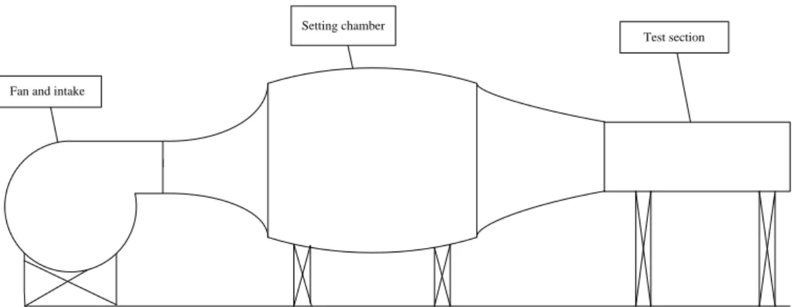
All the experimental research works were conducted in a low speed wind tunnel at the University of Southampton [103] (Figure 3.1).
Setting chamber
Test section
Fan and intake
Figure 3.1: Schematic of the wind tunnel general assembly.
The wind tunnel was designed with a contraction ratio of 4:1 from the settling chamber to the main test section. An axial Halifax fan with 12 blades is driven by a 4 kW three-phase electric motor, providing a maximum fan speed of 1500 rpm. The maximum flow speed attainable in the test section is 25m/s (±0.04m/s). The original test section is 850mm×250mm×350mm in length, height and width, respectively. In this study, the wind tunnel was reassembled in another lab. In order to get enough length for the developing of the required TBL flow, we extended the test section length from 850mm to 1400mm. Subsequently, a new test section was made for the proposed research. Both of the side walls and the ceiling of the new designed test section are fitted with Perspex boards for the access of laser and camera used in the PIV measurements.
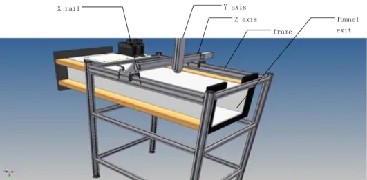
Because the wind tunnel was modified for inducing the required TBL flow, it is necessary to consider the turbulence level in the test section of the wind tunnel and keep its value at a reasonable level. The turbulence level was measured using hot-wire anemometry with a single wire probe. A newly developed traverse system was used to
position the hot-wire (Figure 3.2). frame Z axis Y axis X rail Tunnel exit
Figure 3.2: Traverse system in the wind tunnel.
The traverse system is mounted on a frame cross the wind tunnel ceiling. The two axes (vertical-horizontal) are combined with an Oriental Motor’s motorized cylinder (EZAM4E030MC) mounted on the table of a motorized slide (EZSM4E050MC). The drive motor adopts the closed-loop α stepping motor that eliminates misstep and hunting which can achieve greater convenience and performance in positioning. The accuracy of either cylinder or slide is 0.01mm which provides enough resolution for the flow field measurement. The combination axes are mounted on the slide rail of the frame and can move in the longitudinal direction manually. Two Oriental Motor’s Limo ESMC-C2 linear motion controllers were connected to a PC that operated the traverse system with the provided editing software.
The wire probe was calibrated in the empty wind tunnel with a pitot tube. The hot-wire and pitot tube were located at the centre of the test section but separated by 50 mm in the vertical direction to avoid flow measurement interference. The hot-wire system used for the experimental work employed a Dantec 5μm single component probe connected to a Mini CTA (54T30). The output signal from the bridge unit was fed into an analogue-to-digital converter in a PXI chassis. The data acquisition and processing was described in Figure 3.3.
Figure 3.3: Hot-wire measurement system.
The calibration of the hot-wire anemometry system usually use a King’s Law:
=
Where E is the voltage across the wire, is the velocity of the flow normal to the wire
and A, B, and n are constants, usually n = 0.45. It is common for hot-wire probe
calibration that A and B are found by measuring the voltage, E, obtained for a number
of known flow velocities and performing a least squares fit for the values of A and B
which produce the best fit to the data. The values of A and B depend on the settings of
the anemometer circuitry, the resistance of the wire used, the air temperature, and, to a lesser extent, the relative humidity of the air.
The selected hot-wire was calibrated in a range of freestream velocities. A typical calibration result was shown in Figure 3.4.
Figure 3.4: A typical hot-wire calibration curve.
U(m/s) E (V ) 0 5 10 15 20 25 3.6 3.8 4.0 4.2 4.4 4.6 4.8 5.0 E=8.992+3.718U0.45
The turbulence intensity in the streamwise direction measured by the calibrated hot-wire was presented in Figure 3.5.
Figure 3.5: Wind tunnel background turbulence level.
The results showed that the empty wind tunnel freestream turbulence intensity is about 0.2% which is at a reasonable level for flow control study.
3.1.2 Flat Plate Model
A flat plate was installed 50 mm above the bottom wall of the test section (Figure 3.6). The plate was designed to develop a TBL. The flat plate is 1390mm in length with a 50mm long trailing edge adjustable flap to form a ZPG TBL. The boundary layer was tripped using a combination of a trip wire of diameter 1.5 mm and a roughness strip of length 30 mm. The trip wire is located 20 mm downstream the plate leading edge and the roughness strip is placed 50 mm downstream the trip wire. This combination ensured a self-preserving TBL upstream of the local plasma jet actuator.
A Scanivalve pressure scanner with 48 ports was employed to measure the static pressure distribution along the flat plate floor for adjusting the required ZPG boundary. Because the static pressures along the flat plate floor are very low, a high accuracy Setra 239 transducer was used in the scanner instead of using the original transducer of the
Scanivalve system. The Setra 239 has a range of 0 to 1 inch H2O (249 Pa) with an
accuracy of ±0.14%. The measured relative static pressure ∆p distributions along the
U(m/s) T u rb u le n c e In te n s it y (% ) 5 10 15 20 0.10 0.15 0.20 0.25 0.30
flat plate floor for freestream velocities of 3 m/s, 5 m/s and 10 m/s were shown in Figure 3.7. The results indicate that the required ZPG boundary layer has been formed successfully. 50 flap 1390 100 Top view Side view roughness strip trip wire 50 U X 0
a) Schematic of the flat plate (sketch not to scale).
b) The flat plate in the wind tunnel.
![Figure 2.1: A typical classification of flow control actuators [3].](https://thumb-us.123doks.com/thumbv2/123dok_us/1875143.2773822/26.892.263.736.666.1048/figure-typical-classification-flow-control-actuators.webp)
![Figure 2.5: Velocity component of backward flow [24].](https://thumb-us.123doks.com/thumbv2/123dok_us/1875143.2773822/32.892.320.668.713.1010/figure-velocity-component-backward-flow.webp)
![Figure 2.6: Electric wind velocity for multi-DBD array [24].](https://thumb-us.123doks.com/thumbv2/123dok_us/1875143.2773822/33.892.96.716.368.621/figure-electric-wind-velocity-multi-dbd-array.webp)
![Figure 2.14: Jets driven by (a) steady and (b) stroboscopic illumination [55]](https://thumb-us.123doks.com/thumbv2/123dok_us/1875143.2773822/41.892.147.666.113.502/figure-jets-driven-steady-b-stroboscopic-illumination.webp)
![Figure 2.16: Flow regimes of a circular cylinder [70].](https://thumb-us.123doks.com/thumbv2/123dok_us/1875143.2773822/43.892.183.624.385.998/figure-flow-regimes-circular-cylinder.webp)