High Speed Atomic Force Microscopy of Biomolecules by
Image Tracking
S. John T. van Noort, Kees O. van der Werf, Bart G. de Grooth, and Jan Greve Department of Applied Physics, University of Twente, 7500 AE Enschede, The Netherlands
ABSTRACT An image-tracking procedure for atomic force microscopy is proposed and tested, which allows repeated imaging of the same area without suffering from lateral drift. The drift correction procedure is based on on-line cross-correlation of succeeding images. Using the image-tracking procedure allows zooming in on a small scan area over a long period and thus increases the frame rate inversely proportional to the scan area. Application of the procedure is demonstrated for diffusion of 5.4-kb DNA plasmids. With a scan area of 500p500 nm2, a single plasmid can be imaged for more than 30 min at 4 s per frame, with a drift less than 10 nm. The high temporal resolution allows detailed analysis of the diffusion of DNA molecules. A diffusion coefficient of 30 nm2/s is found for most DNA molecules, though many molecules are temporally pinned to the mica surface, restricting diffusion.
INTRODUCTION
The possibility of operating an atomic force microscope (AFM) in physiological buffers allows visualization of in-dividual biological molecules in their natural environment (Han and Lindsay, 1997; Hansma, 1995). It is this feature that makes the AFM a unique tool to study both the dynam-ics of single molecules and the interactions between indi-vidual molecules (Guthold et al., 1994; (Van Noort et al., 1998). Visualization of molecular processes requires a time resolution at least comparable with the time constant of the process. The acquisition time of a single AFM image of soft biological material, however, is in the order of one minute, which is much slower than most biological processes. To increase the frame rate, the scan velocity can be increased, but this generally results in higher interaction forces that may cause damage to the sample. Another way to increase the frame rate is to reduce the scan area (Lal and John, 1994). If the scan velocity is kept constant, zooming in allows an increase of the frame rate inversely proportional to the scan area.
To get sufficient accuracy of the stochastic movement of individual molecules, it may be necessary to follow the molecules of interest over a long period. Thermal drift of the piezo scanner is then a major problem because it causes the scanner to move away from the original field of view. Performing such an AFM experiment therefore requires a correction of the lateral drift during data acquisition. Such a drift correction procedure should then be flexible, that is, applicable independent of the shape of the sample, reliable, and not time consuming. In this study, we present a general approach for drift compensation based on on-line
cross-correlation of succeeding images. This allows an optimiza-tion of the frame rate by zooming in, while avoiding the problem that drift causes molecules to disappear out of the scanned field of view.
In this paper, we will apply the image-tracking procedure to zoom in on an individual DNA plasmid. Although, for AFM imaging, molecules are usually immobilized on a surface, lateral diffusion of biomolecules only loosely at-tached to the surface and the assembly of protein DNA complexes have been imaged by AFM (Guthold et al., 1999). A complicating factor in visualizing the movement of such loosely attached molecules is the interaction of the scanning tip with the molecules (Hansma and Laney, 1994). Using a high time resolution in combination with an accu-rate drift correction, it should be possible to analyze diffu-sion-related processes of individual molecules in more de-tail. In this analysis, it should be possible to distinguish the influences of the scanning tip from molecular movement by diffusion.
THEORY
Maximum scan velocity
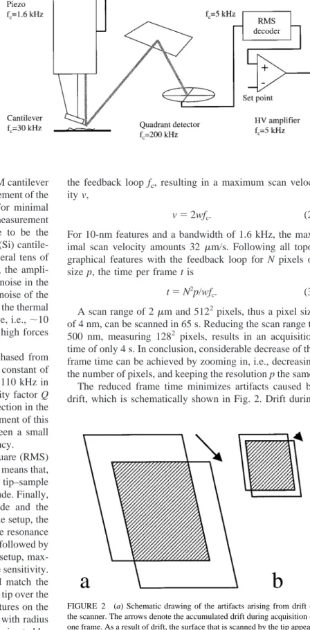
Tapping mode AFM is most often used for imaging biolog-ical samples because of the absence of friction forces (Put-man et al., 1994). Keeping the oscillation amplitude con-stant in a feedback loop controls the tip–sample interaction. The maximal scan velocity of the tip, and thus the maximal frame rate, is limited by the bandwidth of the feedback loop, schematically drawn in Fig. 1.
To achieve maximal scan rate, all components of the feedback loop need to be optimized. The first element in the setup is the force sensor, the cantilever itself. The cantilever behaves as a second-order damped harmonic oscillator and is driven at its resonance frequency. The stiffer the cantile-ver, the higher its resonance frequency and thus the higher the allowed scan velocity. However, stiff cantilevers put high demands on the force detection. The fundamental
Received for publication 19 April 1999 and in final form 28 June 1999.
Address reprint requests to Dr. Bart G. de Grooth, Dept. of Applied Physics, University of Twente, P.O. Box 217, 7500 AE Enschede, The Netherlands. Tel.: 131-53-489-3157; Fax: 131-53-489-1105; E-mail: [email protected].
© 1999 by the Biophysical Society 0006-3495/99/10/2295/09 $2.00
lower limit to the force that is applied by an AFM cantilever is the force that is generated by the thermal movement of the cantilever itself (Gittes and Schmidt, 1998). For minimal damage to occur, the cantilever deflection measurement should be sensitive enough for thermal noise to be the dominant noise source. For this reason, silicon (Si) cantile-vers, with a spring constant in the order of several tens of N/m can be discarded. Using these cantilevers, the ampli-tude of thermal fluctuations is smaller than the noise in the beam deflection scheme that is limited by shot noise of the laser diode. Though the amplitude is very small, the thermal fluctuations in terms of forces can be quite large, i.e.,;10 nN, because of the high spring constant. Such high forces may cause severe damage to the sample.
In this study, we use Si3N4 cantilevers purchased from Park Scientific (Sunnyvale, CA), with a spring constant of 0.5 N/m. The resonance frequency drops from 110 kHz in air to 38 kHz immersed in buffer, and the quality factor Q reduces to;2. The sensitivity of the beam deflection in the setup is just sufficient to measure thermal movement of this cantilever. Thus, a compromise is found between a small spring constant and maximal resonance frequency.
For amplitude detection, a true root mean square (RMS) decoder with a bandwidth of 5 kHz is used. This means that, for a tapping frequency of 30 kHz, only 6 tip–sample contacts are used to measure the tapping amplitude. Finally, the amplified difference between the amplitude and the amplitude set point is applied to the piezo. In the setup, the bandwidth of the feedback loop is limited by the resonance frequency of the piezo, which amounts 1.6 kHz, followed by the bandwidth of the RMS decoder. Using this setup, max-imum bandwidth is combined with optimal force sensitivity. The bandwidth of the feedback loop should match the spatial frequencies that occur while scanning the tip over the surface. The apparent width w of molecular features on the surface is determined by convolution of the tip with radius R and the sample with radius r and can be approximated by w<
Î
rR . (1) For a tip radius of 50 nm, a molecule with a radius of 2 nm results in an image feature of 10 nm. The spatial frequencies of the features in the image should match the bandwidth ofthe feedback loop fc, resulting in a maximum scan veloc-ity v,
v52wfc. (2)
For 10-nm features and a bandwidth of 1.6 kHz, the max-imal scan velocity amounts 32 mm/s. Following all topo-graphical features with the feedback loop for N pixels of size p, the time per frame t is
t5N2p/wf
c. (3)
A scan range of 2mm and 5122pixels, thus a pixel size of 4 nm, can be scanned in 65 s. Reducing the scan range to 500 nm, measuring 1282 pixels, results in an acquisition time of only 4 s. In conclusion, considerable decrease of the frame time can be achieved by zooming in, i.e., decreasing the number of pixels, and keeping the resolution p the same. The reduced frame time minimizes artifacts caused by drift, which is schematically shown in Fig. 2. Drift during
FIGURE 1 Schematic drawing of the AFM setup. The bandwidth is given for each component. In this case, the piezo tube is the rate-limiting factor for tapping-mode AFM.
FIGURE 2 (a) Schematic drawing of the artifacts arising from drift of the scanner. The arrows denote the accumulated drift during acquisition of one frame. As a result of drift, the surface that is scanned by the tip appears stretched and skewed, compared to the movement of the tip. Furthermore, in a succeeding scan, only part of the scanned area, the shaded region, coincides with the area scanned in the previous scan. (b) When the scan area is reduced while maintaining the same pixel resolution and scan velocity, the time per frame decreases proportional to the scan area, and, as a result, both the shift of the scan area and the skewed shape distortion of the scan area caused by drift are reduced.
imaging results in a skewed shape distortion and stretching of the scanned area. Also, as the image range decreases, sequential frames have a relatively larger area in common. The latter effect is counterintuitive because, generally, one uses a larger scan area to prevent features of interest from drifting out of the field of view.
Cross-correlation image tracking
Although zooming in can considerably increase the number of frames that are measured of a single molecule, in prac-tice, the duration of an AFM experiment is still limited. During imaging, thermal drift of the scanner may accumu-late to displacements greater than the scan range, and may cause the molecules to move out of the field of view of the scanner. Thomson et al. (1996) presented a way of solving this problem: by continuously determining the position of a protein under investigation relative to the tip position and repositioning the tip accordingly, proteins could be tracked for more than 1 h. The position of a molecule was measured by cross-wise scanning over the molecule. Using this method, all image information is lost, which, yet, is essen-tial for the determination of the conformation of a molecule or the relative displacement of interacting molecules.
For drift compensation, we propose a very general method based on cross-correlation of succeeding images. The cross-correlation between frames i1and i2is defined as Corr~i1, i2! ;
E
2` `E
2` ` i1~x2sx, y2sy!i2~x2sx, y2sy!dsxdsy, (4)where sx and sydenote the shift of the image in x and y direction. In our implementation, we make use of the dis-crete correlation theorem (Press et al., 1986):
Corr~i1, i2!NI1I*2, (5) where I1and I2represent the Fast Fourier Transform (FFT) of the images i1and i2and the asterisk denotes the complex conjugation. Thus, the product of FFT(i1) and the complex conjugate of FFT(i2) is inversely transformed, resulting in the cross-correlation of the images. Drift between two frames is measured from the position at which the maxi-mum in the cross-correlation occurs. In the succeeding scan, a negative offset that compensates for the measured drift is applied to the scanner. In this way, drift is compensated on-line. The method is limited to nonperiodic features, because, in periodic structures, multiple peaks will appear in the correlation image. If enough common features appear in succeeding frames, the image-tracking procedure provides a stable method to compensate for lateral drift of the scanner.
Surface diffusion of DNA molecules
In this paper, we use diffusion theory, commonly used for single particle tracking (Qian et al., 1991), to quantify
diffusion of a single DNA molecule. A sequence of nf digitized frames is obtained showing the detailed position and conformation of DNA molecules in time. For diffusion analysis, the position of the center of mass of a single DNA plasmid is followed in time. For all NDNApixels that rep-resent one DNA molecule, the center of mass cmis calcu-lated as cm,x5 1 NDNA
O
i NDNA xi cm,y5 1 NDNAO
i NDNA yi. (6)To follow the movement of the plasmid, the mean square displacement (MSD) of the center of mass is calculated. The MSD can be expressed in terms of n times the acquisition time of a single frame t as
MSDx~nt!5
O
i50 nf2n @cm,x~i1n!2cm,x~i!#2 nf2n11 , MSDy~nt!5O
i50 nf2n @cm,y~i1n!2cm,y~i!#2 nf2n11 . (7)In the case of simple diffusion, the MSD should be propor-tional with time,
MSD54Dnt (8)
using a diffusion coefficient D.
A plot of the MSD versus time should be linear if the movement of the molecule is characterized by diffusion only. Due to the stochastic movement of the molecule, however, the trajectory of the center of mass of a single molecule will show statistical variations around such a linear behavior. Only by averaging sufficient data points can the MSD be measured accurately. The standard deviation
sMSDof the MSD can be expressed in terms of the number of data points and the time resolution of the measurement as (Qian et al., 1991)
sMSD2 5
2n211 3n@nf2n11# ~
4Dnt!2. (9) Therefore, an accurate determination of the diffusion char-acteristics benefits from a high frame rate and a long time range over which the molecule is followed.
MATERIALS AFM setup
For the experiments, a home-built stand-alone AFM was used, as described elsewhere (Van der Werf et al. 1993). Triangular Si3N4cantilevers (Park
Scientific, Sunnyvale, CA) with a spring constant of 0.5 N/m were used for tapping mode in liquid, at a frequency of 30 kHz, a free-oscillation amplitude of 10 nm, and an amplitude setpoint of 8 nm. The data acqui-sition and image-tracking procedure was implemented in a LABView (National Instruments, Austin, TX) programming environment using an AT-MIO-16E data acquisition board (National Instruments). For scanning, software-generated scan arrays are applied to the piezo tube. After acqui-sition of the second frame, the cross-correlation with the previous frame is
calculated, and the scan arrays are adjusted to compensate for the measured drift, before automatic acquisition of the next frame. On a Pentium II 350 MHz PC, the cross-correlation algorithm typically takes less than 1% of the frame time; thus the frame-acquisition rate is not significantly reduced by the procedure.
Sample preparation
Five microliters of a solution containing 1 ng/mL 5.4 kb plasmid (pcDNA3), 5 mM MgCl2, 10 mM Hepes pH 7, and 20 mM KCl was
pipetted onto a freshly cleaved mica disk. After approximately 30 s, the AFM was mounted onto the sample, and 200mL, 5 mM MgCl2, 10 mM
Hepes pH 7, and 20 mM KCl buffer was added to the liquid cell. In this way, dehydration of the DNA was avoided. Immediately after mounting the AFM, it was possible to start the experiment; it was not necessary to wait for thermal equilibrium of the scanner.
Data analysis
Off-line data processing and analysis was implemented in interactive data language (IDL) (Research Systems, Boulder, CO). Image processing con-sisted of line subtraction, by fitting a second-order polynome to each line, and subtraction of this fit. For off-line cross-correlation, the drift was measured between two frames, and the second frame was shifted accord-ingly to correct for drift. For determination of the center of mass of DNA
plasmids, all pixels with a height of 0.5 nm or higher were used, except obvious pollution particles, which were manually discarded.
RESULTS
Cross-correlation of AFM images
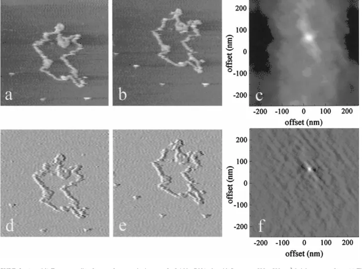
Two typical unprocessed topography images of a 5.4-kbp DNA plasmid are shown in Fig. 3, a and b. The apparent width of the DNA strand is 20 nm, allowing a frame time of approximately 4 s with a scan range of 500 nm. The DNA molecules are loosely attached to the surface and, though parts of the molecules remain at the same position, other parts have moved between acquisition of frames a and b. Despite the very weak attachment to the surface, DNA molecules are not swept away by the scanning tip. The cross-correlation image of Fig. 3, a and b is plotted in Fig. 3 c. A maximum is observed at a displacement of 30 nm in the x direction and 70 nm in the y direction. Image artifacts, like tilt of the surface or drift of the scanner perpendicular to the surface, sometimes dominate the topography image over real topographical features. An elegant way to avoid
FIGURE 3 (a and b) Two succeeding frames of topography images of a 5.4-kbp DNA plasmid. Scan area, 500p500 nm2, height range55 nm. (c) The
corresponding cross-correlation image. (d and e) The simultaneously acquired error-mode images, and (f) their cross-correlation. At a displacement of 30 (x), 70 (y) nm, a maximum in the cross-correlation image occurs that corresponds to the drift between imaging the two frames.
low-frequency artifacts is by using the error-mode image for image tracking. The error-mode, which is the amplitude signal in the case of tapping mode AFM, produces differ-entiated topography images, especially sensitive for edges (Putman et al. 1992). The error-mode images corresponding to Fig. 3, a and b are plotted in Fig. 3, d and e. The amplitude signal can be regarded as the band-pass-filtered topography image, with a lower cutoff frequency deter-mined by the bandwidth of the feedback loop, and an upper cutoff frequency determined by the bandwidth of the RMS amplitude detector. Thus, only features that occur with a frequency between 1.6 and 5.0 kHz contribute to the error-mode image. The edges of topographical features, like the molecules under investigation, are included in this band-width, but tilt and vertical drift of the scanner generally have a much lower frequency and do not contribute to the error-mode image. The cross-correlation of Fig. 3, d and e is shown in Fig. 3 f and shows a sharper, more distinct peak than that of the unprocessed topography image. Using the error-mode for cross-correlation image tracking proved to be much more reliable than using topography images.
Drift compensation by image tracking
The cross-correlation algorithm was implemented in the data acquisition software, and, before acquisition of the next frame, the measured drift between two previous frames is fed back to the piezo scanner to compensate for it. In this measurement, a firmly bound DNA molecule that hardly showed any motion during the measurement, was followed in time. During the acquisition of a sequence of frames, the voltage necessary for the drift compensation is recorded. In Fig. 4 a, the accumulation of drift of a typical experiment is plotted as a function of time. The scan range was 500 nm measuring 1282pixels, at a frame time of 4 s. During the measurement, the average drift amounted 0.1 nm/s in the x direction and 0.2 nm/s in the y direction. At the end of the experiment, the total drift accumulated to more than 200 and 400 nm in the x and y directions, respectively. Without image tracking, after 40 min, only 12% of the area scanned in the first frame would still be in the field of view of the last frame.
To check the accuracy and reliability of the on-line im-age-tracking algorithm, we measured the residual drift of the images by a similar off-line cross-correlation algorithm. However, instead of the previously acquired frame, we used the first frame of the sequence as a reference to prevent accumulation of errors in the drift measurement. This pro-cedure was applied to the topography images that were corrected for tilt and vertical drift by line subtraction of a second-order polynome. The resulting drift is plotted in Fig. 4 b. The error in the image-tracking procedure amounted only 663 nm, and never exceeded 10 nm. Small errors in the drift compensation do not accumulate, because, during 40 min, the residual drift does not show a systematic in-crease. Thus, on-line image tracking provides a reliable and accurate way to correct for drift.
Mobility of DNA plasmids
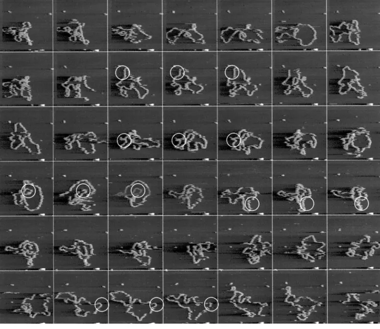
Although the image-tracking procedure is very reliable for stationary features, it can also be used to compensate for drift when imaging moving features. We used the image-tracking algorithm to keep track of a 5.4 kb DNA plasmid that was only loosely bound to the surface. In Fig. 5, part of a sequence of images measured at a frame rate of 4 s per frame is shown. To be able to follow this molecule, image tracking was necessary as drift exceeded several hundreds of nanometers during the experiment. Because at least some parts of the molecule do not move between succeeding frames, cross-correlation of the images still results in an accurate drift measurement. Pollution particles that are also present in the image remain at the same location during the sequence of images, confirming accurate drift compensation.
The DNA mobility of this plasmid is not the representa-tive for all molecules. We observed a large variation in the mobility of DNA molecules that is also expressed in the quality with which the topography image can be measured. In Fig. 6, c and e, two typical frames of other, similar DNA plasmids in the same buffer are plotted. In the case of Fig.
FIGURE 4 (a) Lateral drift as measured by on-line image tracking as a function of time. Drift amounted to 0.2 nm/s in the x direction and 0.3 nm/s in the y direction. (b) Residual error calculated off-line. The error was obtained by using the cross-correlation algorithm, but now each frame was compared with the first frame of the sequence instead of the previous one. The error in the drift compensation is less than 10 nm.
6 e the mobility of the plasmid is so high that the topogra-phy image shows apparently uncorrelated features that can-not be reconstructed to the shape of the DNA plasmid. However, based on the height of these features, and the size of the area in which these features are clustered, we con-clude that they represent a very fast-moving DNA plasmid. However, to get a clear image of this plasmid, an even much better time resolution would be necessary. Even when the topography signal recording the scanning a single line is compared with the topography signal that is recorded on the linescan back, which has a delay of only 15 ms, a very faint correlation is measured. The time resolution is, in this case, at least one order of magnitude too small for an accurate measurement of the conformation of the molecule. How-ever, the cross-correlation procedure still works, which was confirmed by qualitative evaluation of the peak in the
cross-correlation image. In all cross-cross-correlation images, a distinct peak occurred (data not shown), which is necessary for reliable measurement of the drift.
Diffusion analysis of DNA plasmids
An important issue that needs to be addressed when imaging very loosely immobilized molecules with AFM is the effect of the scanning tip on the mobility of these molecules (Van Noort et al. 1998; Guthold et al. 1999). By using the theory of diffusion analysis as discussed in the theory section, the influence of the scan direction and scan velocity can be studied quantitatively, despite the fact that only very small movements of the plasmid are measured. Although the conformation of a DNA plasmid can sometimes not be
FIGURE 5 Sequence of consecutive topography images of a single 5.4-kb DNA plasmid on mica followed in time. Scan area, 500 p500 nm2,
corresponding to 1282pixels; height range55 nm; frame rate 0.25 Hz. Pollution particles form convenient position markers and show negligible drift
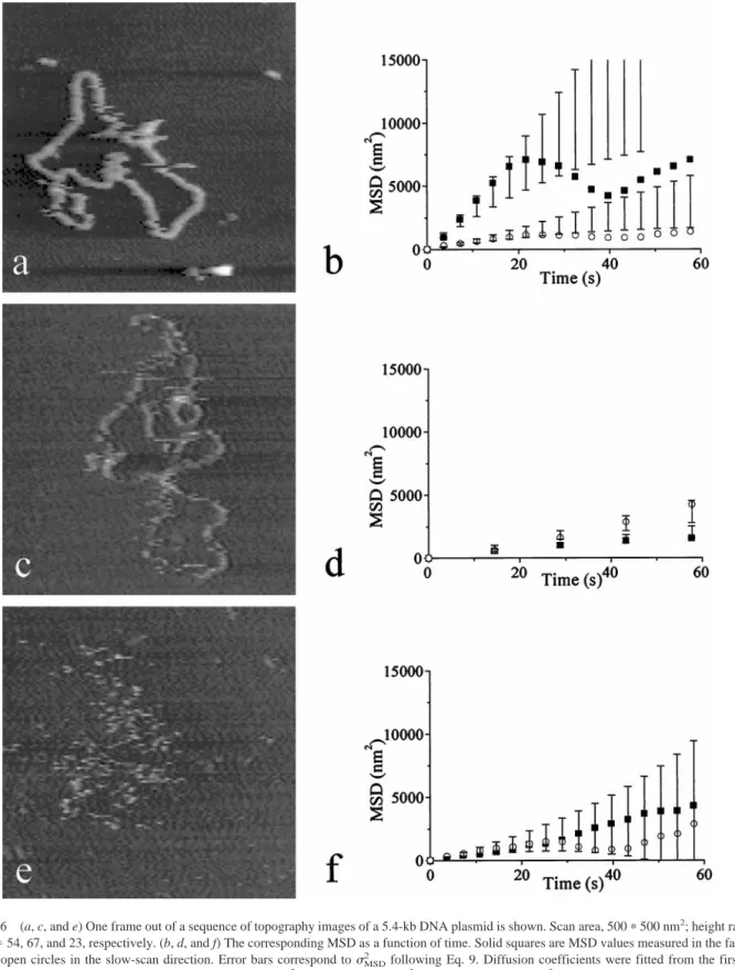
reconstructed from the topography image, its center of mass can still be calculated fairly accurately, though it is averaged over the frame time. In Fig. 6, b, d, and f, the MSD trajectory of the molecules in Fig. 6, a, c, and e is plotted for the scan direction and perpendicular to the scan direction.
The standard deviation of the MSD measurement as calcu-lated by Eq. 9 is plotted as error bars in Fig. 6, b, d, and f. Although the slope of the MSD plot, and thus the diffusion coefficient, should be direction independent, in Fig. 6, b and d, a significant difference is observed between the diffusion
FIGURE 6 (a, c, and e) One frame out of a sequence of topography images of a 5.4-kb DNA plasmid is shown. Scan area, 500p500 nm2; height range5
5 nm; nf554, 67, and 23, respectively. (b, d, and f) The corresponding MSD as a function of time. Solid squares are MSD values measured in the fast-scan
direction, open circles in the slow-scan direction. Error bars correspond tosMSD2 following Eq. 9. Diffusion coefficients were fitted from the first three
points, resulting in diffusion coefficients of (b) 158 and 33 nm2/s, (d) 18 and 27 nm2/s, and (f) 31 and 28 nm2/s, in the fast- and slow-scan directions,
coefficient in the fast-scan direction (horizontal) and the slow-scan direction (vertical).
In the case of the plasmids shown in Fig. 6, a and c, this observed difference in slope, and thus the difference in diffusion coefficient, exceeds the expected statistical varia-tion of the MSD. The difference however, cannot be attrib-uted to the scanning tip. This is evident because, in Fig. 6 d, diffusion in the fast-scan direction has a higher diffusion coefficient, whereas in Fig. 6 b, diffusion in the fast-scan direction has a lower diffusion coefficient. If the scanning tip was influencing the movement of the DNA, the observed diffusion coefficient should also vary with the scan velocity. Except for the diffusion observed in the slow-scan direction in Fig. 6 a, all the measured diffusion coefficients have the same magnitude of approximately 30 nm2/s. Figure 6 c, however, was imaged at a frame rate 4 times less than the frame rate in Fig. 6, a and e, which apparently did not influence the measured diffusion coefficient. Thus, differ-ences in mobility of the center of mass of the DNA plasmids are not likely to originate from tip-induced distortions, in contrast to previous reports where the mobility of photol-yase protein was studied (Van Noort et al. 1998).
The MSD trajectory shown in Fig. 6 b is typical for a molecule that is locally pinned to the surface. In Fig. 5, some parts of the molecule that remain fixed during at least three images are denoted with a circle. However, the regions of DNA that are pinned to the surface do not remain fixed during the entire series of frames, which can be seen in Fig. 5. Temporary fixation of the plasmid does have a major influence on the dynamics of the molecule as shown in both the MSD trajectory and the topography image. In a few instances, a streak or a sudden change in conformation appears. This may well be tip-induced: by tapping on the molecule, it may come loose from the surface. By introduc-ing a dwell time between acquisition of successive images, this effect can be studied.
The plasmid shown in Fig. 6 e shows unrestricted diffu-sion. The MSD increases linearly in time, and the slope of the MSD is equal for both scan directions. Deviations from a linear fit fall well within the expected standard deviation of the MSD versus time plot. As a result of unrestricted diffusion, the movement of the DNA plasmid is too fast for imaging by AFM. Using the image-tracking procedure ther-mal drift of the scanner did not limit the duration of the imaging experiment. The experiments were stopped when part of the molecule itself diffused out of the scan area. Although the image-tracking procedure still works when molecules are only partly in the scan area, the center of mass cannot be determined accurately, which would affect the diffusion analysis.
DISCUSSION AND CONCLUSION
The scan velocity of tapping mode AFM is limited by the hardware of the setup. Custom-made cantilevers with a high resonance frequency may help to increase the scan velocity
(Walters et al., 1996), but these cantilevers are not easily available and they would require additional modifications of the existing AFM hardware as well.
Zooming in allows an increase of the frame rate, without extra damaging of the sample. Thus, images of 500p500 nm2of a single DNA molecule can be measured at only 4 s/frame for more than 200 frames without visible damage. To prevent drift that causes the molecules to move out of the scanned area, we have described a simple and reliable method to correct for thermal drift. An image-tracking al-gorithm allows zooming in on a small area over a long period. Because the error-mode image contains only fea-tures with spatial frequencies that correspond to small to-pographical features and excludes image artifacts like tilt or drift of the scanner, for on-line applications, using the error-mode image as input for the algorithm yields a more reliable result than using the topography image. The proce-dure can be applied independent of the sample shape, pro-vided that succeeding frames have enough nonperiodical features in common. Using the image-tracking algorithm, we measured in the setup a drift of typically 0.2 nm/s, comparable with values reported in literature (Thomson et al., 1996). Off-line application of the cross-correlation pro-cedure may be used additionally to correct for residual drift. By using the image-tracking procedure, the positions of fixed pollution particles, which form convenient position markers, on mica remain stable for at least 80 min, despite a significant drift of the scanner.
The high frame rates and the large number of frames allow single-particle tracking analysis, which is commonly used in studies on single molecules. DNA plasmids on a mica surface show a linear dependence of the MSD on time. Although only relatively small movements are observed, compared to the size of the molecule, displacement of the center of mass represents intramolecular movements rather than displacement of the entire molecule. The diffusion analysis, however, is still very useful to assess the influence of a scanning tip on the mobility of the molecule. Different values are sometimes obtained for directions parallel and perpendicular to the scan direction. Although this direc-tional dependence points at disturbance of free diffusion by the tip, the effect seems not to be related to scan velocity. Local pinning of the DNA plasmids on mica can account for the observed behavior. Temporary immobilization of parts of the plasmids restricts diffusion and will decrease the MSD at long time intervals. This explains why the deviation from a linear dependence of the MSD on time is greater than that expected from the measurement inaccuracy.
The mechanism of the interaction between DNA and mica in MgCl2buffer has been the subject of discussion in several papers (Hansma and Laney, 1996; Rivetti et al., 1996). Differences in the composition of mica are presum-ably responsible for the poor reproducibility of these exper-iments. Guthold et al. (1999) report free two-dimensional diffusion of DNA fragments on Mg-treated mica. In a previous study, we have shown that immobilization of DNA on mica can be located at distinct points on the mica surface
(Van Noort et al., 1998). In the present study, we observed a large variation in the mobility of DNA plasmids and, despite the reproducibility of the measured diffusion coef-ficient of the center of mass of the plasmid, the appearance of the DNA molecule varied a lot.
The measured diffusion coefficients of the center of mass in this paper are one order of magnitude higher than those observed in a study by Guthold et al. (1999). Different batches of mica and different buffer solutions may account for this, but the poor reproducibility of the mobility of DNA makes it hard to evaluate these effects. The high mobility of the DNA may facilitate studies of protein DNA interactions because less hindrance by the surface can be expected when DNA is only loosely bound to the surface (Keller, 1998).
A frame rate one order of magnitude higher than gener-ally achieved with an AFM allowed visualization and de-tailed analysis of the diffusion of these relatively mobile molecules. Application of the image-tracking procedure will simplify future experiments, visualizing single mole-cules with an AFM at a high temporal resolution, and will increase the accuracy of relative displacement determina-tion of these molecules.
This work was supported by the Dutch Stichting voor Fundamenteel Onderzoek der Materie grant 94BR1231.
REFERENCES
Gittes, F., and C. F. Schmidt. 1998. Thermal noise limitations on micro-mechanical experiments. Eur. Biophys. J. 27:75– 81.
Guthold, M., M. Bezanilla, D. A. Erie, B. Jenkins, H. G. Hansma, and C. Bustamante. 1994. Following the assembly of RNA polymerase-DNA complexes in aqueous solutions with the scanning force microscope.
Proc. Natl. Acad. Sci. USA. 91:12927–12931.
Guthold, M., X. Zhu, C. Rivetti, G. Yang, N. H. Thomson, S. Kasas, H. G. Hansma, B. Smith, P. K. Hansma, and C. Bustamante. 1999. Real-time imaging of one-dimensional diffusion and transcription by Escherichia
coli RNA polymerase. Biophys. J. In press.
Han, W., and S. M. Lindsay. 1997. Kinked DNA. Nature. 386:563. Hansma, H. G. 1995. Atomic force microscopy of biomolecules. J. Vac.
Sci. Technol. B 14:1390 –1395.
Hansma, H. G., and D. E. Laney. 1994. Motion and enzymatic degradation of DNA in the atomic force microscope. Biophys. J. 67:245–249. Hansma, H. G., and D. E. Laney. 1995. Applications for atomic force
microscopy of DNA. Biophys. J. 68:1672–1677.
Hansma, H. G., and D. E. Laney. 1996. DNA binding correlates with cationic radius: assay by atomic force microscopy. Biophys. J. 70: 1933–1939.
Keller, D. 1998. Making movies of molecular motions. Biophys. J. 74: 2743–2744.
Lal, R., and S. A. John. 1994. Biological applications of atomic force microscopy. Am. J. Physiol. 266 (Cell Physiol. 35):C1–C21
Press, W. H., B. P. Flannery, S. A. Teukolsky, and W. T. Vetterling. 1986. Numerical Recipies. Cambridge Press, New York.
Putman, C. A., K. O. van der Werf, B. G. de Grooth, N. F. van Hulst, J. Greve, an P. K. Hansma. 1992. A new imaging mode in atomic force microscopy dase on error signal. SPIE Scanning Probe Microsc. 1693: 198 –204.
Putman, C. A., K. O. van der Werf, B. G. de Grooth, N. F. van Hulst, and J. Greve. 1994. Tapping mode atomic force microscopy in liquid. Appl.
Phys. Lett. 64:2454 –2456.
Qian, H., M. P. Sheetz, and E. L. Elson. 1991. Single particle tracking, analysis of diffusion, and flow in two-dimensional systems. Biophys. J. 60:610 – 621.
Rivetti, C., M. Guthold, and C. Bustamante. 1996. Scanning force micros-copy of DNA deposited onto mica: equilibration versus kinetic trapping studied by statistical polymer chain analysis. J. Mol. Biol. 264:919 –932. Thomson, N. H., M. Fritz, M. Radmacher, J. P. Cleveland, C. F. Schmidt, and P. K. Hansma. 1996. Protein tracking and detection of protein motion using atomic force microscopy. Biophys. J. 70:2421–2431. van der Werf, K. O., C. A. Putman, B. G. de Grooth, F. B. Segerink, E. H.
Schipper, N. F. van Hulst, and J. Greve. 1993. Compact stand-alone atomic force microscope. Rev. Sci. Instr. 64:2892–2897.
Van Noort, S. J. T., K. O. van der Werf, A. P. M. Eker, C. Wyman, B. G. de Grooth, N. F. van Hulst, and J. Greve. 1998. Direct visualization of dynamic protein–DNA interactions with a dedicated atomic force mi-croscope. Biophys. J. 74:2840 –2849.
Walters, D. A., J. P. Cleveland, N. H. Thomson, and P. K. Hansma. 1996. Short cantilevers for atomic force microscopy. Rev. Sci. Instr. 67: 3583–3590.