Improving the Configuration Management of
Large Network Security Systems
Jo˜ao Porto de Albuquerque1,2?, Holger Isenberg2, Heiko Krumm2, and Paulo L´ıcio de Geus1
1 Institute of Computing, State University of Campinas, 13083-970
Campinas/SP Brazil{jporto,paulo}@ic.unicamp.br
2 FB Informatik, University of Dortmund, 44221 Dortmund Germany
{joao.porto,heiko.krumm,holger.isenberg}@udo.edu
Abstract. The security mechanisms employed in today’s networked en-vironments are increasingly complex and their configuration manage-ment has an important role for the protection of these environmanage-ments. Especially in large scale networks, security administrators are faced with the challenge of designing, deploying, maintaining, and monitoring a huge number of mechanisms, most of which have complicated and heteroge-neous configuration syntaxes. This work offers an approach for improving the configuration management of network security systems in large-scale environments. We present a configuration process supported by a mod-elling technique that uniformly handles different mechanisms and by a graphical editor for the system design. The editor incorporates focus and context concepts for improving model visualisation and navigation.
1
Introduction
In today’s large networked environments security is a major concern. A great variety of security technologies and mechanisms are employed in these environ-ments in order to offer protection against network-based attacks. Whilst signifi-cant progress has been made on improving network security technology in recent years, only quite modest attention has been given to its configuration interface. In practice, a security administrator must deal with a variety of complex and heterogeneous configuration syntaxes, most of which are unintuitive and in some cases even misleading.
The situation is especially dramatic in large-scale environments where it is very hard to have a global view of the numerous security mechanisms that have to be put into harmonic cooperation. In these situations, a single maladjustment be-tween two mechanisms can leave the whole system vulnerable. Approaches that offer proper abstraction, integration and tool support for managing the configu-ration of security mechanisms are thus key factors for making the configuconfigu-ration process less error-prone and more effective.
Four basic tasks of the network security configuration management can be distinguished: i) the design of the security system, including the definition of
technologies and mechanisms to be employed, as well as the placement of the diverse security components over the network; ii) the deployment of the de-signed configuration; ii) configuration maintenance, enabling the introduction of changes to achieve adaptability in face of new requirements; iv) monitoring of the system during run-time to assure compliance with expected behaviour.
This paper addresses the three first phases of the configuration management process. To support the design phase, we use a modelling technique that allows the design of the security system to be managed in a modular fashion, by means of an object-oriented system model [8]. This model is segmented into logical units (so-calledAbstract Subsystems) that enclose a group of security mechanisms and other relevant system entities, and also offer a more abstract representation of them. In this manner, the system administrator is able to design a security system—including its different mechanism types and their mutual relations—by means of an abstract and uniform modelling technique.
A software tool supports the modelling, providing a graphical editor. This editor incorporates the concept of focus & context—that originated from re-search on information visualisation—through the techniques of fisheye-view [11] and semantic zooming [3, 7]. Furthermore, our work builds upon the policy hi-erarchy [6] and model-based management [5] approaches in order to assist the above-mentioned configuration management phases of deployment and main-tenance. A system model organised in different abstraction layers thus affords a step-wise, tool-assisted system modelling, along with an automated policy re-finement that culminates in the generation of low-level configuration parameters. While this guided derivation of parameters contemplates the deployment of the security configuration, its maintenance is supported by the possibility of editing the models and repeating the automated generation process.
The rest of the paper is organised as follows: Sect. 2 presents the main el-ements of our modelling technique, and Sect. 3 describes the focus & context techniques incorporated into the support tool. Subsequently, Sect. 4 presents a case study that exemplifies the practicality of these approaches within a typical large-scale networked environment. In Sect. 5 our results are compared to related work. Finally, Sect. 6 casts conclusions for this paper.
2
Modelling Technique
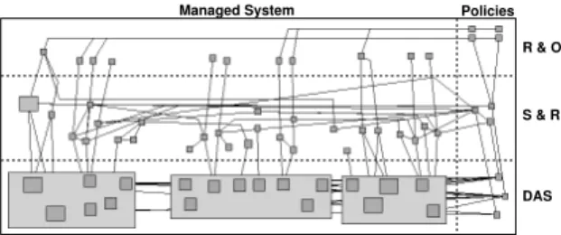
Our modelling builds upon the Model-based Management approach [5] and em-ploys a three-layered model whose structure is shown in Fig. 1. The horizontal dashed lines of the figure delimit the abstraction levels of the model: Roles & Objects(RO),Subjects & Resources(SR), andDiagram of Abstract Subsystems (DAS). Each of these levels is a refinement of the superior one in the sense of a “policy hierarchy” [6]; i.e. as we go down from one layer to another, the abstract system’s view contained in the upper level is complemented by the lower-level system representation, which is more detailed and closer to the real system. As for the vertical subdivision, it differentiates between the model of the actual managed system and the security policies that regulate this system.
DAS S & R R & O
Managed System Policies
Fig. 1.Model Overview
As the lowest level of the model (DAS) is the focus of the present work, it is explained in detail in the next section. The two uppermost levels (RO and SR) have been adopted from previous work on model-based management, and thus will be presented briefly.
The RO level is based on concepts from Role-Based Access Control (RBAC) [10]. The main classes in this level are:Rolesin which people who are working in the modeled environment act;Objects of the modeled environment that should be subject to access control; andAccessModes; i.e. the ways of accessing objects. The class AccessPermission expresses a security policy, allowing the performer of a Roleto access a particularObjectin the way defined byAccessMode.
The second level (SR in Fig. 1) offers a system view defined on the basis of the services that will be provided, and it thus consists of a more complex set of classes. Objects of these classes represent: (a) people working in the modeled environment (User); (b) subjects acting on the user’s behalf (SubjectTypes); (c) services in the network that are used to access resources (Services); (d) the dependency of a service on other services (ServiceDependency); and lastly (e) Resources in the network.
2.1 Diagram of Abstract Subsystems
The main objective of the Diagram of Abstract Subsystems (DAS) is to describe theoverall structure of the system in a modular fashion; i.e. to cast the system into its building blocks and to indicate their interconnections. As such, a DAS is, formally speaking, a graph comprised of Abstract Subsystems (ASs) as nodes and edges that represent the possibility of bi-directional communication between two ASs. An AS, in turn, contains an abstract view of a certain system segment; i.e. a simplified representation of a given group of system components that may rely on the following types of elements:
Actors: groups of individuals which have an activebehaviour in a system; i.e. they initiate communication and execute mandatory operations according to obligation policies.
Mediators: elements that intermediate communication, in that they receive
requests, inspect traffic, filter and/or transform the data flow according to theauthorisation policies; they can also perform mandatory operations based onobligation policies, such as registering information about data flows.
Targets: passive elements; they contain relevant information, which is accessed byactors.
Connectors: represent the interfaces of one AS with another; i.e. they allow information to flow from, and to, an AS.
Each element of the typesActors,MediatorsorTargets represents a group of system elements that have a relevant behaviour for a global, policy-oriented view of the system. As for theConnectors, they are related to the physical interfaces of an AS (for a detailed explanation on the modelling of abstract subsystems we refer to [8]). In this manner, a DAS supports the reasoning about the structure of the systemvis-`a-visthe executable security policies, thus making explicit the distribution of the different participants of these policies over the system.
Furthermore, in order to model the security policies themselves, another ob-ject type is also present in a DAS: ATPathPermissions (ATPP). An ATPP is associated with a path (p) in a DAS that connects an Actor (A) to a Target (T), possibly containing a number ofMediators andConnectors along the way. It expresses the permission for pto be used by A in order to accessT. In this manner, each ATPP models an authorisation policy. The ATPP objects in the system are not defined by the modeller, but rather derived automatically in a process that is explained later in Sect. 4.4.
Additionally, each AS in a DAS is also associated with a detailed view of the system’s actual mechanisms. This expanded view encompasses objects that represent hosts, processes, protocols and network interfaces of the system (this detailed view is related to the level PH of the works on model-based manage-ment [5]) and supports the process of automated generation of configuration parameters (Sect. 4.4).
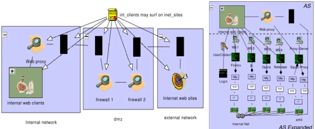
Example of DAS. An example of DAS is shown in Fig. 2. This diagram
corresponds to a simple network environment with three ASs: “internal network”, “dmz” (demilitarised zone) and “external network”. In the “internal network”, the object “internal web clients” is anActor representing a group of processes that are authorised to access the processes mapped by theTarget “internet web sites” (in the “external network”) through the Mediator “Web proxy”, by the ATPP “int clients may surf on inet sites”.
Figure 3 shows both the abstract and the expanded view for the AS “internal network” (leftmost of Fig. 2). Each object in the abstract view of the AS is then related to the elements that model the corresponding real entities of the system; for instance, the Actor “internal web clients” is associated with its respective Process-typed objects. This double representation of an AS provides the designer with a flexible model of the system that offers not only a more abstract, concise and understandable description of the system’s structure, but also a detailed view of its mechanisms. It also constitutes the basis for applying the techniques presented in the next section.
external network Internet web sites
Internal network internal web clients
Web proxy
dmz firewall 1 firewall 2
int_clients may surf on inet_sites
internal web clients
Squid−Proxy eth0 Netscape WS 4 Internal Net Proxy−Server UserCredential Login Web proxy WS 1 WS 2 WS 3 Firefox IE Opera AS Expanded AS
Fig. 2.Example of DAS Fig. 3.Expanded AS
3
Focus & Context
The term focus & context refers to techniques that allow a user to centre his view on a part of the model that is displayed in full detail (focus), while at the same time perceiving the wider model surroundings in a less detailed manner (context). The major advantage of using these techniques is the improved space-time efficiency for the user; i.e. the information displayed per unit screen area is more useful and, consequently, the time required to find an item of interest is reduced as it is more likely to be already displayed [7]. We employ thefocus & context concept within two different methods, described in the next sections in turn.
3.1 Semantic Zooming
The concept ofsemantic zooming [7, 3] is based on the ability to display model objects in different abstraction levels, depending on their distance from the fo-cus. Thus, objects inside the focused region of a diagram are exhibited in their full detailed form, whereas objects located at the borders are shown in the most simplified way. The regions between these two extremes are displayed with inter-mediary levels of detail. In this manner, the presented information is selectively reduced by adjusting the level of detail in each region to the user’s interest in this region.
In our context, there are two classes of compounded objects to which semantic zooming is applied:typed folders andAbstract Subsystems. A typed folder is an object that aggregates a group of objects of same class (or type), for the sake of the representation conciseness. On the other hand,Abstract Subsystems contain objects of various classes (Sect. 2.1) and may also enclosetyped folders. In both cases, the level of detail shown can be changed by the selective display of internal objects.
In the simplest situation, two different representations of typed folders are available: a closed (all internal objects are hidden) and an open folder view. As
for the ASs, three different levels of abstraction are used: i) a full detailed view that includes all the internal objects (as in Fig. 3); ii) an abstract representation encompassing only the objects of the abstract view (as in Fig. 2); and iii) a “closed” view in which none of the internal objects are displayed.
3.2 Fisheye View
The term fisheye view is used for the type of projection created by a fisheye lens used in photography. This type of lenses achieves a 180◦ field of view and
is uncorrected. It results in an optical enlargement of objects near the centre in relation to those at the borders. This feature emulates the human visual perception, which by the effect of the eye movements has a clear focused area and a gradual loss of visual resolution in the direction of the peripheral regions. A fisheye view combines thereby a complete image overview with a gradual degradation of detail that increases with the distance from the focus—and it is thus well suited to implement the concept offocus & context. In contrast to semantic zooming, the fisheye view manipulates the displayed size of the objects in order to change the amount of information shown.
We build upon the practical application of fisheye views for graph visuali-sation offered by Sarkar and Brown [11]. In our tool, the focus area can also be freely moved by the user throughout the model. In this way, objects within the focused area are displayed in an enlarged scale whereas the others become gradually smaller as they are approach the model borders.
4
Configuration Design and Deployment Process
To illustrate the practical application of the previously described concepts, in this section we analyse a paradigmatic case study. The considered scenario is that of an enterprise network, composed of a main office and branch office, that is connected to the Internet. Our main goal is to assist the security administrator in the task of designing the configuration for the security mechanisms that are required to enable and control web-surfing and e-mail facilities for the company’s office employees.
Therefore, the highest-level security policies for this environment can be stated as follows:P1: The employees may surf on the Internet from the comput-ers in the main and branch offices; P2: The employees may read their internal e-mails from the main and branch offices, and from home; P3: The employees may send e-mail to external and internal addresses;P4: Internet users may ac-cess the corporate web server; P5: Internet users may send e-mail to internal mail addresses.
Having as input the above abstract policy statements and previously de-scribed scenario, we apply our modelling technique by providing in the next sections a step-by-step description of the configuration design process, passing through the different abstraction layers.
Internal Users WWW proxy service @main office LDAP directory remote access @branch office WebPages WWW service Internet webservice Internet webpages @Internet Anonymous Communication−encryption service Service dependency association Incoming e−mail
Company’s Worker
Internal e−mail fetching
sending to the Internet
Internet WWW surfing
Anonymous Internet user
Website acessing
allow sending e−mail
sending to the Company
Internet e−mail
Internal mail service
Internal message storage Radius service
Mail−forwarding service incoming mail Mail−forwarding service outgoing mail
Internet mail−service
Internet message storage Ldap service
Service dep.assoc. incoming radius
permit receiving e−mail allow internet surfing
allow fetching internal mail permit access to company’s web
ServiceDependencyAssociation outgoing Web
ServiceDependencyAssociation outgoing Mail
RO level SR level
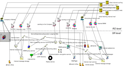
Fig. 4.Model of the levels RO and SR
4.1 Modelling of the RO level
Since the highest level in our model is based on RBAC concepts (Sect. 2), the designer starts the development process by mapping the abstract policies, ex-pressed in natural language, to the more formal syntax of RBAC. The top of Fig. 4 shows the resulting model at the RO level for our considered scenario. The basic objects are: theRoles “Company’s Worker” and “Anonymous Inter-net User”, and theObjects “Internal e-mail”, “Website”, “Internet e-mail” and “Internet WWW”. These objects are associated toAccesModes by means of five AccessPermissions (at the top, on the right of Fig. 4), each of the latter corre-sponding to one of the abstract policy statements of the previous section. Thus, for instance, the AccessPermission “allow Internet surfing” models the policy statement P1, associating the role “Company’s Worker” to “surfing” and “In-ternet WWW”. The other policy statements are analogously modeled by the remainingAccessPermissions.
4.2 Modelling of Users, Services and Resources
The second step in the design process consists of the definition of the services that the system must provide, the resources they need, and the users who may take advantage of them. In our example, theUser“Anonymous” and the Subject-Type “@Internet” are defined in association with the role “Anonymous Internet User”. For the role “Company’s Worker”, several User objects are grouped in the TypedFolder (Sect. 3.1) “Internal Users”, and three SubjectTypes are de-fined: “@main office”, “@branch office” and “@remote access” (at the bottom of Fig. 4). These objects map the three types of session that can be established by an employee in the considered scenario, depending on his physical location.
As for the modelling of services and resources, aService object will be ba-sically defined for each AccessMode in the RO level, whereas RO Objects will be mapped to SR Resources. In case where more than one service is needed to provide access to a resource, this fact is expressed by a ServiceDependency. This is what happens in our example model, for instance, with theAccessMode “sending to the company” that is related to theService“Mail-forwarding service incoming mail”. This service must rely on the “Internal mail service” in order to provide access to the resource “Internal message store” (which is associated with the ROObject “Internal e-mail”).
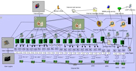
4.3 Modelling of Abstract Subsystems
In order to produce a Diagram of Abstract Subsystems, the designer shall start with the identification of the major segments in which the system is subdivided. Considering our example and also accounting consolidated network security tech-niques, a structural subdivision into five blocks can be defined: the internal net-work, the demilitarised zone (dmz), the branch office netnet-work, the remote access points and the remaining external network (the Internet). Therefore, the DAS for this example has an AS for each one of these segments.
Afterwards, the modeller must define, for each subsystem, the security mech-anisms and other relevant network elements with respect to the security policies; i.e. to model the expanded view of each AS (Sect. 2.1). The bottom of Fig. 5 shows the expanded AS “internal network”. It has objects that represent pro-cesses running on seven workstations, one mail server, one web proxy and one LDAP server. Each one of these processes is connected through the adequate protocol stack—modeled by a series of interconnected corresponding protocol objects—to their network interfaces.
Subsequently, the abstract view of each AS must be defined by the creation of objects forActors,Mediators,Targets andConnectors, and their associations to the objects of the SR level must be established. This is accomplished by classifying the behaviour of the elements of the expanded view into one of these classes (the mapping of the abstract view in ASs is further elaborated in [8]).
TheActors “internal mail clients” and “internal web clients” (see Fig. 5) are created in the “internal network” to map the processes of this subsystem with active behaviour in our example. They are also both connected to the objects in the SR level that map the same behaviour: “Internal Users” and “@main office”. Due to their intermediary or supporting functions, theMediators “Web proxy” and “LDAP Server” are created and connected to the corresponding processes in the expanded view; they also connect these processes with the appropriate services in the SR level. Proceeding in an analogous manner for all of the re-maining ASs in our example, a complete DAS is achieved and the whole system model is complete.
Internal Users
User Credentials
User Logins
internal web clients
internal mail clients Internal mail server Web proxy LDAP server Squid−Proxy eth0 eth0 Netscape Exchange−Server eth0 10.1.1.8 Mail−Server Outlook
Internal Mail Files
Internal Net
Proxy−Server LDAP−Server
eth0 LDAP−Prozess
Ldap Pages FirefoxThunderbird IEThunderbirdOperaK−Mail
Firefox IE Outlook IEThunderbird KMail
10.1.2.* 10.1.20.* 10.2.1.* 10.2.4.* 10.2.3.* 10.2.7.*
10.1.1.80 10.1.1.7 10.4.5.*
WWW proxy service
@main office LDAP directory
Internal mail service
Internal message storage Ldap service
Fig. 5.Extract of a DAS and its relation to the SR level
4.4 Policy Refinement and Configuration Generation
After inputting all model levels, the system design phase is complete and the security administrator can take advantage of our support tool to deploy the con-figuration parameters for the security mechanisms modeled. This is accomplished by an automated building of a policy hierarchy, starting from the abstract se-curity policy defined by the designer in the RO level (Sect. 4.1) and deriving lower-level policies on the basis of the model entities of the levels SR and DAS. Thus, the support tool first derives each one of the given AccessPermis-sions through a series of intermediary objects, ultimately generating a set of ATPathPermissions (Sect. 2.1). Finally, for the last step of the configuration deployment, a series of back-end modules are executed, where each module cor-responds to a special security service product (e.g. Kerberos, FreeS/WAN, Linux IP tables etc.). These back-end functions evaluate theATPathPermissions and the expanded views of the ASs in order to automatically generate the adequate configuration files for each of the security mechanisms (an extensive explanation on the policy refinement process is beyond the scope of this paper and can be found in [9, 5]).
4.5 Model Editing, Navigation and Visualisation
During the model editing needed to accomplish the tasks described in the pre-vious sections, in order to edit specific parts of large models (such as the one used for our case study), a designer must rely on model cutout enlargement tech-niques; i.e. on zooming. However, with the standard method of zooming that is based on linear enlargement of a fixed-size model cutout, the model navigation and visualisation are problematic. Consider, for instance, the simple design task
of connecting an object in the model area that is currently edited to another one that is located at the opposite extreme of a large model. In this case, “large” means that the whole model does not fit into the screen when scaled to a size that makes its editing possible. With the standard zooming method one needs to perform the following steps: 1) scale down, in order to be able to see the entire model; 2) estimate the locations of the target and source objects in the out-zoomed view, and the angle of the edge needed to connect them; 3) enlarge the area around the source object, in order to be able to select it; 4) select the source; 5) drag a new edge from the source into the direction of the previously estimated angle (the enlarged region of the model moves automatically following the mouse); 6) stop the dragging once the target can be seen on the screen; 7) drop the edge on the target object.
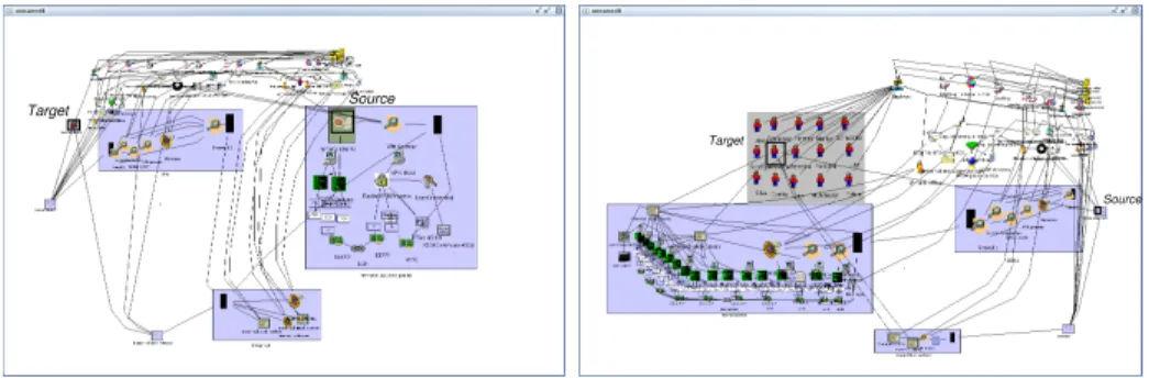
On the other hand, with the use of a fisheye view only the following steps are needed: 1) activate the fisheye view mode; 2) select the source object, which is displayed inside the enlarged focus area (as in the left hand picture of Fig. 6); 3) drag a new edge from the source into the direction of the target, whose location can be simultaneously seen in the down-scaled surroundings; (the focus follows the mouse during this process, so that the target can eventually be seen in detail, as in the right hand picture of Fig. 6); 4) drop the edge on the target object.
Target Source
Target
Source
Fig. 6.Fisheye view with focus centred at the source and target nodes
Therefore, using a fisheye view reduces the number of steps needed by almost half. Furthermore, the usage is immediately intuitive, since the designer never loses of sight the full context of the model, and the non-linear adaptive scaling seems “natural” in contrast to the sharp border between linear enlarged cutouts and their surroundings.
Combined Focus & Context. Since the two techniques introduced in Sect. 3 operate on orthogonal subjects—namely, fisheye view on graphics and semantic zooming on structure—they can be combined. We accomplish this by using the scale factor resulting from the fisheye transformation function to adjust the abstraction level which is used to display compound elements.
The result of this is that as the distance between the focus and a certain ob-ject increases, this obob-ject is gradually presented in a more abstract view—which per sehas a smaller graphical representation—and also graphically miniaturised by the fisheye function. Thus, a larger focused area is made possible even if the context is still visible, which leads to an optimisation of the screen space.
In Fig. 6, the effect of this combined use can be seen. In the left hand picture, the AS “remote access point” (that encloses the source node) has the focus: it is thus displayed in a higher scale and in its full level of details, allowing editing. The ASs “dmz” and “Internet” pertain to a close context and are shown in their abstract representation, gradually smaller in size; whereas the miniaturised and “closed” views of the remaining ASs save screen space while still enabling the user to perceive their existence.
5
Related Work
Though there are several applications offocus & contexttechniques for improving the usability of generic graph editors (including the recent applications to UML in [7] and the more generic approach in [3]), as far as we know, they have not yet been used in the context of model visualisation and navigation for network security system design.
In a wider context, Damianouet al.[2] present a set of tools for the specifica-tion, deployment and management of policies specified in the Ponder language. The tool prototype includes a domain browser that uses fisheye views to handle large structures. While centring the approach in the policies, this work does not provide a representation of the architecture of the system to be managed, mak-ing it hard for the system designer to associate the policies with his/her mental model of the system. A further work by these authors offers an approach to the implementation and validation of Ponder policies for Differentiated Services us-ing CIM to model network elements [4]. CIM concentrates on the modellus-ing of management information (e.g. device’s capabilities and state) while our model represents the whole relevant structure of the managed system together with the management components.
The graphical tool Firmato [1] seems to be the closest approach to ours, since it supports the interactive policy design by means of diagrams and automatically derives the corresponding configurations for mechanisms. However, since the abstraction levels of policy definitions and configuration parameters are relatively near to each other, its support is restricted to an abstraction level that is close to the mechanisms.
6
Conclusion
This paper has presented an approach for the configuration management of large network security systems that builds upon and extends previous work on Model-based Management [5] and on the Diagram of Abstract Subsystems [8, 9]. We add to these works by proposing a general design process that is centred around the
system administrator and encompasses four steps that range from the abstract policy modelling to the generation of low-level configurations. In this manner, the abstract policy representation is gradually brought into a more concrete sys-tem view, bridging the gap between high-level security policies and real syssys-tem implementation.
We also combine the use of a modelling technique specially conceived to achieve scalability with focus and context techniques, thereby allowing the de-signer to define in detail a certain model part without losing sight of the system as a whole. Therefore, we expect our methodology to contribute to making the configuration management of security technologies in large-scale network envi-ronments more effective and closer to the security administrator. Current work concentrates on the representation of policies at the lower model levels, in order to enhance their handling.
References
1. Y. Bartal, A. J. Mayer, K. Nissim, and A. Wool. Firmato: A novel firewall
man-agement toolkit.ACM Transactions on Computer Systems, 22(4), November 2004.
2. N. Damianou, N. Dulay, E. Lupu, M. Sloman, and T. Tonouchi. Tools for
domain-based policy management of distributed systems. In IEEE/IFIP Network
Opera-tions and Management Symposium (NOMS2002), Florence, Italy, 2002.
3. O. K¨oth and M. Minas. Structure, abstraction, and direct manipulation in
dia-gram editors. InDiagrammatic Representation and Inference, Second International
Conference (Diagrams 2002), volume 2317 ofLecture Notes in Computer Science, Callaway Gardens, GA, USA, 2002. Springer.
4. L. Lymberopoulos, E. Lupu, and M. Sloman. Ponder policy implementation and
validation in a CIM and differentiated services framework. InIFIP/IEEE Network
Operations and Management Symposium (NOMS 2004), Seoul, Korea, April 2004.
5. I. L¨uck, S. V¨ogel, and H. Krumm. Model-based configuration of VPNs. InProc.
8th IEEE/IFIP Network Operations and Management Symposium NOMS 2002, pages 589–602, Florence, Italy, 2002. IEEE.
6. J. D. Moffett and M. S. Sloman. Policy hierarchies for distributed system
man-agement. IEEE JSAC Special Issue on Network Management, 11(9), 11 1993.
7. B. Musial and T. Jacobs. Application of focus + context to UML. InAustralian
Symposium on Information Visualisation, volume 24 of Conferences in Research and Practice in Information Technology, Adelaide, Australia, 2003. ACS.
8. J. Porto de Albuquerque, H. Krumm, and P. L. de Geus. On scalability and
modularisation in the modelling of security systems. In10th European Symposium
on Research in Computer Security (ESORICS 05), volume 3679 of LNCS, pages 287–304, Heidelberg, Germany, September 2005. Springer Verlag.
9. J. Porto de Albuquerque, H. Krumm, and P. L. de Geus. Policy modeling and
refinement for network security systems. InPOLICY ’05: Proceedings of the Sixth
IEEE International Workshop on Policies for Distributed Systems and Networks (POLICY’05), pages 24–33, Washington, DC, USA, 2005. IEEE Computer Society. 10. R. S. Sandhu, E. J. Coyne, H. L. Feinstein, and C. E. Youman. Role-based access
control models. IEEE Computer, 29(2):38–47, 1996.
11. M. Sarkar and M. H. Brown. Graphical fisheye views of graphs. InProceedings of
ACM CHI’92 Conference on Human Factors in Computing Systems, Visualizing Objects, Graphs, and Video, pages 83–91, 1992.