Accepted Manuscript
Apparatus: A Framework for Security Analysis in Internet of Things
Systems
Orestis Mavropoulos, Haralambos Mouratidis, Andrew Fish,
Emmanouil Panaousis
PII:
S1570-8705(18)30593-6
DOI:
https://doi.org/10.1016/j.adhoc.2018.08.013
Reference:
ADHOC 1743
To appear in:
Ad Hoc Networks
Received date:
1 December 2017
Revised date:
22 May 2018
Accepted date:
18 August 2018
Please
cite
this
article
as:
Orestis Mavropoulos,
Haralambos Mouratidis,
Andrew Fish,
Emmanouil Panaousis, Apparatus: A Framework for Security Analysis in Internet of Things
Sys-tems,
Ad Hoc Networks
(2018), doi:
https://doi.org/10.1016/j.adhoc.2018.08.013
This is a PDF file of an unedited manuscript that has been accepted for publication. As a service
to our customers we are providing this early version of the manuscript. The manuscript will undergo
copyediting, typesetting, and review of the resulting proof before it is published in its final form. Please
note that during the production process errors may be discovered which could affect the content, and
all legal disclaimers that apply to the journal pertain.
ACCEPTED MANUSCRIPT
Apparatus: A Framework for Security Analysis in
Internet of Things Systems
Orestis Mavropoulos · Haralambos Mouratidis · Andrew Fish · Emmanouil Panaousis
Received: date / Accepted: date
Abstract Internet of Things (IoT) systems are ubiquitous, highly complex and dy-namic event-based systems. These characteristics make their security analysis challeng-ing. Security in IoT requires domain-specific methodologies and tools. The proposed methodologies need to be able to capture information from software and hardware constructs tosecurity andsocial constructs. In this paper, in addition to refining the modeling language of theApparatusFramework, we propose a class-based notation of the modeling language and a structured approach to transition between different mod-els.Apparatusis a security framework developed to facilitate security analysis in IoT systems. We demonstrate the application of the framework by analyzing the security of smart public transport system. The security analysis and visualization of the system are facilitated by a software application that is developed as part of theApparatus
Framework.
Keywords IoT security · security requirements ·smart cities security · Apparatus Framework
1 Introduction
Internet of Things (IoT) is a research area that has attracted considerable attention. One of the fundamental characteristics of IoT systems is their dynamic nature [1–3], O. Mavropoulos
Centre for Secure, Intelligent and Usable Systems University of Brighton
E-mail: [email protected] H. Mouratidis
Centre for Secure, Intelligent and Usable Systems University of Brighton
E-mail: [email protected] A. Fish
Centre for Secure, Intelligent and Usable Systems University of Brighton
E-mail: [email protected] E. Panaousis
Surrey Centre for Cyber Security, University of Surrey E-mail: [email protected]
ACCEPTED MANUSCRIPT
where the state of devices varies during the system’s lifecycle. Devices in an IoT network change their state continuously since they connect and disconnect, sleep and wake up. The resting location, as well as the moving speed of the devices, may change at any time. From a security perspective, this means it is important to ensure security control effectiveness over time in a highly dynamic environment of operation with changing security requirements, threats, and vulnerabilities.
Smart cities are dynamic, complex and large-scale applications of IoT. They include multiple computing paradigms such as Edge and Fog computing along with a large number of stakeholders. Different IoT applications within the same smart city have different security requirements, despite that the security requirements are elicited by the same poll of stakeholders. For example, a smart application of public transport has different security requirements from the same stakeholders than a smart application of a city-wide weather monitor service.
Enabling the security analysis of such large-scale and dynamic systems, such as smart cities is a significant research challenge. Traditional security requirements engineering and network security use a static approach. In a static approach, the majority of security mechanisms are deployed around the external facing nodes of a network. It follows the phrase “We want our network to be like a M&M, with a hard crunchy outside and a soft chewy center”. Static security is becoming less appealing in the modern computing paradigm, where network boundaries are becoming more and more blurred. In a world where more and more devices and services are becoming interconnected, the sophistication and complexity of attacks are increasing. In order to secure an IoT system, we require mechanisms and tools that can interact with their environment to alter their security according to the facing threats.
1.1 Contributions
This paper aims to address is how to perform a security analysis in a smart city public transport application using the Apparatus Framework. Specifically, we extend our previous work [4–6] in theApparatusFramework by refining the following components of the Framework:
1. A conceptual model for expressing an IoT system during the design phase. Design phase models are used to identify high-level security components such as security policies and stakeholders’ requirements.
2. A conceptual model for expressing an IoT system during the implementation phase. To identify and propose low-level security components such as security mechanisms and system vulnerabilities.
3. A step-by-step approach to navigate between the design and implementation phase models.
4. A class-based notation of the modeling language of the Framework.
The paper is structured as follows: Section 2 describes the related work in the fields of IoT modeling and IoT security modeling. Section 3 presents the proposed metamodels for IoT systems and transformation rules. Section 4 describes a security analysis of a smart public transport application using the proposed metamodels. Section 5 concludes this paper and discusses limitations and future extensions of the present work.
ACCEPTED MANUSCRIPT
2 Related Work
The literature has provided us with a number of works that visualize and model specific aspects of IoT systems. Many of those works focus on modeling thesensor aspect of IoT while other works focus on modeling theservices provided by an IoT system.
In their work about Service-Oriented Middleware for the IoT [7, 8], the authors propose an ontology for IoT. Their ontology models three aspects of the real world present in the IoT. The first aspect is the Thing described in a Device Ontology. The second aspect consists of concepts and functionality of “things”, modeled in a Domain Ontology as mathematical formulas, and third is an approximation aspect that describes models to be used to approximate unavailable services and estimate missing information. This work does not take into account the security issues that can be faced in an IoT system and does not provide a way to model the social components of IoT systems.
OntoSensor [9] constructs an ontology-based descriptive specification model for sen-sors by excerpting parts of SensorML [10] descriptions and extending the IEEE Sug-gested Upper Merged Ontology (SUMO). Another ontology that models network sensors is SenaaS [11]. The approach of SenaaS is sensor-as-a-service by realizing the event-driven service-oriented architecture (SOA) in IoT domain. A similar approach is used by De et al. [12] in their work about service modeling of IoT. Their model captures the components of the IoT domain and provides a formal representation of the inter-actions. Their work is based on SENSEI [13]. SENSEI was aimed at realizing ambient intelligence in future networks and service environments by developing a framework of universal service interfaces for wireless sensor and actuator networks (WSANs). The core modeling concept considered in SENSEI is the “resource”, with all sensors, actua-tors, and processors being modeled as resources. All those works have in common the modeling of IoT sensors, IoT services or both. The social aspects of such networks are not taken into account and as such the ontologies do not provide a way to model users and people. Another concept missing is the security aspect of those networks.
An ontology for a security-enabled Internet of Things with a focus on the interop-erability was proposed by Alam et al. [14]. They propose a functional architecture of the IoT framework that incorporates secure access provision. Their work aims to ad-dress how different security attributes and constraints lying in different administrative domains will work together to secure an integrated operation. Their paper highlights an important security issue faced by IoT systems: how the same system is affected by different administrative domains.
Ikram et al. [15] express IoT systems using a chemical computing approach. They argue that the complexity of IoT can be modeled in a similar manner to chemical computing models. Their model can express social components using the User Plane. Laghari et at. [16] use the Cognitive Agent-based Computing (CABC) framework to model a Complex communication network. They can model social constructs with the use of Agent. Both works do not model the security of an IoT system.
The works described were not developed for security analysis or modeling social interactions in IoT systems. Instead, they focused on modeling specific aspects of IoT. While focus only on specific domains can offer valuable insights, it is not helpful when performing security analysis on large-scale systems that are composed of different do-mains. For such environments require a holistic approach to security analysis. Envi-ronments such as smart cities, which have a multitude of applications, devices, and stakeholders. They represent systems with a large attack surface and as well as complex interconnected relationships. The Apparatus Framework aims to provide a holistic approach to facilitate modeling and security analysis in IoT systems. This is done by
ACCEPTED MANUSCRIPT
providing a language with constructs to express the sociotechnical components of a sys-tem, in addition to processes for identifying threats and vulnerabilities of such systems.
3 Modeling language of Apparatus
The modeling language is used to create IoT systems models for security analysis. The modeling language is composed of metamodels that define concepts to express IoT sys-tems in different layers. An IoT system is essentially a network of various devices and for that reason, the initial core concepts of the conceptual model are the device and the network connection [4]. Using the information provided by the architecture of an IoT system along with the requirements of the system’s stakeholders, security require-ments can be elicited. However, security analysis in the architectural level offers both advantages and limitations. The architecture of a system offers valuable information for security analysis, such as the supported protocols of network connections between nodes or the flow of data inside a network. On the other hand, certain aspects of a system are not expressed, such as user interaction or authentication mechanisms. Limitations of a hardware architectural approach can be mitigated by introducing non-hardware architectural concepts along with hardware architectural components. The conceptual model of Apparatusis modular. The concepts of the modeling language are grouped into different modules based on their thematic context, to allow a security engineer to only use the modules that are needed. Since IoT has computer networking components, concepts from computer networks such asnetwork connectionsandnetwork domains as well as concepts from generic modeling languages such asactor, are incorporated in Ap-paratus. The security requirements concepts that are used are modeled after the Secure Tropos security requirements method [17]. Secure Tropos was chosen because it is an established requirements engineering method whose security concepts align with other requirements methods such as work by Haley [18]. It enables security engineers familiar with those methods to quickly get acquainted withApparatussecurity concepts.
We define a security requirement as a “a restriction related to security issues, such as privacy, integrity and availability, which can influence the analysis and design of a multiagent system under development by restricting some alternative design solutions, by conflicting with some of the requirements of the system, or by refining some of the system’s objectives”, an approach used by Secure Tropos concept of security con-straint [19]. A similar definition of security requirements is given by Haley [18]. He defines them as “constraints on the system’s functional requirements, rather than being themselves functional requirements”.
The modeling language is composed of two metamodels. The first metamodel pro-vides concepts and constraints to model an IoT system during the design phase. The second metamodel provides concepts and constraints to model IoT systems during the implementation phase. The distinction is made due to the different requirements and different information engineers have about a system during each phase. During the de-sign phase, an engineer models the idea of the system without being restricted by the hardware or software specifications. For example during the design phase, an engineer may require a system component that will function as an Intrusion Detection (IDS) system. The engineer may not know at the design time whether the IDS will be a hard-ware device or a softhard-ware application. During the implementation phase whether the IDS will be a hardware device or a software application is necessary since it affects both the topology of the network and its security requirements. During the implemen-tation phase engineers have more information about the IoT system, such as versions of software applications, operating network ports, user profiles and external facing nodes.
ACCEPTED MANUSCRIPT
Information about the system’s architecture can be included in the modeling instances of the IoT system to produce more accurate results.
Each phase offers different types of security analysis. During the design phase, an engineer can model the threats and the vulnerabilities of the system. Design phase secu-rity analysis cannot be used to express specific vulnerabilities of the system or secusecu-rity mechanisms that aim to mitigate them. Both the vulnerability and the security mech-anism are concepts of an implemented system since they represent specific weaknesses or improvements on the hardware or software components of a system.
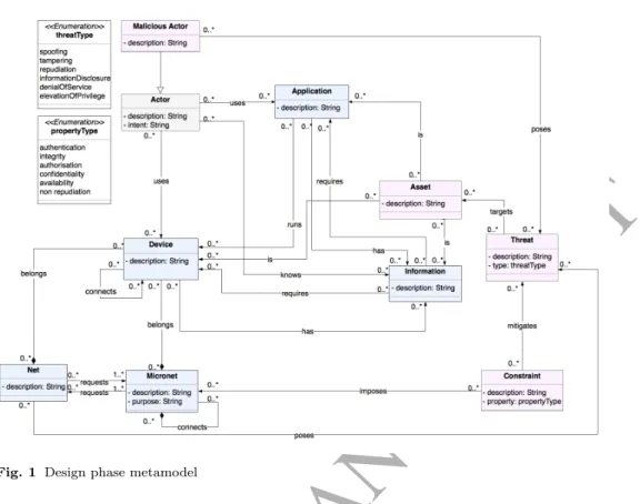
3.1 Design Phase Metamodel
The design phase metamodel provides a set of rules that design phase IoT models must adhere to. The metamodel is defined via a UML class diagram. Each UML class defines a concept that either describes an component of the system or behavior that impacts that system. Concepts are composed by a set of attributes that capture specific infor-mation of the model. Each concept, unless otherwise noted has the propertydescription
which describes the component of the IoT system. The design phase metamodel has the following concepts:
3.1.1 Network module
1. Device: initially named IoT node in [4]. It is an object of the physical world (physical thing) or an object of the virtual world (virtualized thing). It is used to represent either physical components, such as hardware-based actuators and mobiles phones or virtualized components, such as cloud-based devices of an IoT system [1]. 2. Application:is part of the information world (information thing). An Application
represents a software component that is running on a Device.
3. Micronet: is an environment that a security engineer can configure in terms of their security. A Micronet is a managed environment that constitutes a collection of Devices and Applications enable an IoT system to perform a function. Examples of Micronets are a smart home, an agricultural network of sensors or a company’s internal network. The boundaries of the Micronet are defined during the model creation by the engineer. For example, one Micronet can include only the devices that are part of a specific network domain, while another can include all the devices that are in the same room. The same device can belong to both Micronets and each Micronet can impose different security controls on the devices. The property of the Micronet is:
(a) purpose:describes the goal or the function of the Micronet.
4. Net: represents environments that their security configuration is not known and their behavior cannot be configured by the security engineer. While Nets may not be malicious, they represent a level of danger to an IoT system that must taken into account during the model development. Similarly to the Micronet, the boundaries of a Net are defined by the engineer. Examples of the Net are external networks to the IoT system that a security engineer either has little or no knowledge of, such as a third party cloud infrastructure or hostile deployment environments. It is possible, that the same device can be part of Net and a Micronet. For example, an IoT system has a server that hosts a set of virtual machines to its users. While the engineer can configure the server, the usage of the virtualized assets of the servers are configured by the users. Malicious user can try to exploit the virtualized assets in order to compromise the server. As a result, the virtualized assets compose a Net.
ACCEPTED MANUSCRIPT
5. Information: is represents either hard data, such as authentication logs and tem-perature data, or soft data, such as access credentials and user passwords.
3.1.2 Social module
1. Actor: is used to represent people or groups of people that interact with an IoT system [19]. An Actor can be a stakeholder of the system. An Actor may never be malicious. The concept of Actor can be used to represent groups of people with different privileges, such as root users or the administrative personnel of a University. The property of the Actor is the following:
(a) intent: describes what the Actor wants to achieve or gain by interacting with the IoT system.
3.1.3 Security module
1. Asset: any actor, device, application or information of the system that either (1) is considered valuable by the stakeholders and needs to be protected; (2) a mali-cious actor wants; or (3) acts as a stepping stone to further attacks. While assets that are valuable by the stakeholders can be elicited requirements phases, assets that malicious actor wants or can be used for further attacks are not always appar-ent [20]. Examples of assets are the access credappar-entials known by an actor, sensitive information stored in a database or a sensor that has read/write privileges to a server.
2. Threat:a function that can be used maliciously or a system that has the means to exploit a vulnerability of a legitimate system. A threat can only target an asset of the IoT system. The property of the threat is:
(a) threatType: represents the classification of the threat according to the STRIDE acronym [21].
3. Constraint:is “a restriction related to security issues, such as privacy, integrity, and availability, which can influence the analysis and design of a system under develop-ment by restricting some alternative design solutions, by conflicting with some of the requirements of the system, or by refining some of the system’s objectives” [19]. The constraint has the following property:
(a) propertyType:the classification of the constraint according to the extended CIA triad [22].
3.2 Implementation Phase Metamodel
The implementation phase metamodel [4] refines the design phase with additional con-cepts and attributes. The added concon-cepts and attributes represent information that is not known in the design phase and is beneficial for security analysis. A security engineer has more detailed knowledge of an IoT system and better understanding of its security requirements. For example, in the implementation phase, the security engineer knows the type of network protocols that will be used by the system. Moreover, the software versions of the devices that provide services to the system are known. That additional information can be used to elicit security issues that were not apparent in the design phase. We can leverage implementation specific knowledge to either automate or semi-automate certain types of security analysis. For example, the process of vulnerability identification requires hardware and software information. For the majority of the cases,
ACCEPTED MANUSCRIPT
Fig. 1 Design phase metamodel
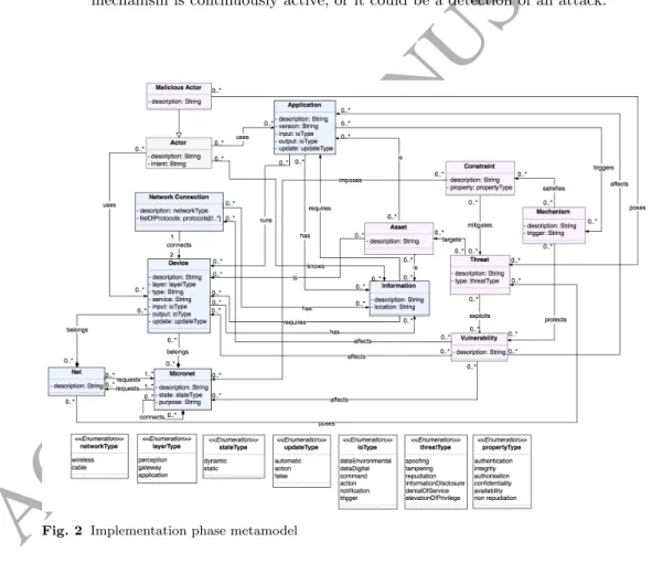
vulnerability identification of a system requires penetration testing. Security engineers will gather information of a system through various means and then use that infor-mation to identify the system’s vulnerabilities. By incorporating that inforinfor-mation into a model, we can perform the process of vulnerability identification without affecting the actual IoT system. An added benefit is that engineers are able to experiment with various models that represent different system configurations to evaluate their attack surface. The proposed metamodel is shown in Fig. 2:
The refined concepts of the implementation phase are the: (1) Device; (2) Applica-tion; (3) Micronet and (4) Information. The added concepts are: (1) Vulnerability and (2) Mechanism.
The modules of the implementation phase metamodel along with their concepts are the following:
3.2.1 Network Module
1. Device: implementation phase concept, refines the design phase Device concept with additional attributes. The added properties of the Device are:
(a) layer: the conceptual layer of the IoT architecture to which the Device belongs.
Apparatususes a three-layer architecture that consists of the Application Layer, Network Layer and the Perception Layer [23,24]. Other works identify other ar-chitectures that provide more levels of abstraction. For example, a Service Ori-ented Architecture based approach identifies five layers, application, service com-position, service management, object abstraction, objects [25]. Another approach by Lu, identifies other layers, that are application, middleware, coordination, backbone network, existed alone network, access layer, edge technology [26]. The
ACCEPTED MANUSCRIPT
proposed architectures for IoT have yet to fuse into a single reference model [27], for that reason we chose the three-layer approach. It provides the necessary prop-erties for reasoning about security while allowing to be extended if more levels of abstraction are introduced into the final reference model of IoT. The layers of IoT architecture should not be confused with the OSI model [28] since the two models try to conceptualize different constructs and concepts. The value of the
layer attribute can be (1) application, (20 gateway or (3) perception;
(b) type: is used to define the kind of the Device. Examples of a Device type are a sensor, a mobile phone or a server;
(c) service: is the type of role or operation that the Device performs for the system. This value may include network services such asssh,ftp, data processing filtering and relaying of data;
(d) input: what is required in order for the node to perform its role or operation. It takes an enumerated value as an input that is dataEnvironmental, dataDigital, command, action, notification, trigger;
(e) output: is the result of the Device operation or role. It may take the same values as theinput property;
(f) update: how the software on the Device is being updated. The updates can be automatic, require a specific action or false.
2. Network Connection: the type of network communication protocol used between the Devices. The properties of the network connection are:
(a) description: the type of connection, it can either be wireless, signifying a con-nection using a wireless protocol orcable, signifying a connection using a wired medium. It takes an enumerated value as an input;
(b) listOfProtocols: is a list of the supported network protocols by the network con-nection. It takes an array of string values as an input, each value in the array represents a supported network protocol.
3. Application: implementation phase concept refines the design phase concept of Application with additional attributes. The properties of the Application are: (a) version: the software’s version type number. For example, if the Application
represents the iOS operating system, the version would be the iOS release version, such as v10.2.3.
(b) update: how the Application is being updated. The updates can be automatic, require a specific action or false.
4. Micronet: implementation phase concept refines the design phase concept with an additional attribute. The property of the Micronet is:
(a) state: the nature of a Micronet in terms of its Device network connectivity gate-way layer. The state can either be dynamic, meaning that the Devices in the network change network domains during their usage orstatic meaning that the Devices in the system do not change network domains. Examples of dynamic IoT systems are networks of vehicular fleets, drones, and other mobile devices since devices in such networks move distances geographically. Examples of static IoT are smart homes and industrial IoT systems since devices in such systems are stationary during their lifecycle.
5. Information: implementation phase concept that extends the design phase concept of Information with an added attribute. The additional attribute of Information is: (a) location: corresponds to the geographical location of the information stored in the device. It can be used to represent if information (data) is physically stored inside a network or are hosted by a third-party service. Moreover different regions have different laws regarding digital information that ultimately affect the overall security of a system and the proposed constraints of the system.
ACCEPTED MANUSCRIPT
3.2.2 Security Module
1. Vulnerability: a software, hardware or usage policy weakness that can be exploited by an adversary toward compromising a system. Hardware and Software Vulnera-bilities can be identified using techniques such as penetration testing. Hardware and software vulnerabilities can be identified from public access vulnerability databases such as CVE 1 and NVD2. Such databases store vulnerabilities using unique IDs.
Vulnerabilities IDs are used by security engineers to exchange information about security incidents.
2. Mechanism: a Mechanism when implemented protects against one or more Vul-nerabilities. If the Vulnerability is publicly identified and stored in a vulnerability database, a security engineer can use the proposed security mechanisms in order to mitigate it. A Mechanism could be applied dynamically when a certain event is detected by the system or they can be a constant process. For example, during the event of DoS attack, a system may enlist additional resources to spread the impact of the attack. Once the attack is mitigated, the system will release the additional resources reduce its operational costs. The property of Mechanism is:
(a) trigger:is used to describe the behavior or event that will cause the application of the Mechanism. For example, a trigger could be a constant, meaning that the mechanism is continuously active, or it could be a detection of an attack.
Fig. 2 Implementation phase metamodel
1 https://cve.mitre.org/cve/ 2 https://nvd.nist.gov/vuln/search
ACCEPTED MANUSCRIPT
Identical constructs, such as fields of sensors, users with the same privileges or software applications that have the same configuration, can be modeled either as a single node or individual nodes. That choice is given to the security engineer that develops the model. An engineer may choose to include all nodes in a model to better assess the attack of the system. To analyze a large system, an engineer can tackle the complexity by using specialized software tools. ASTo has a number of functions that facilitate the analysis of large systems by applying a class-based notation system.
3.3 Notation in theApparatus
Models of theApparatusFramework are represented in the form of graphs. Concepts are represented as graph nodes and the relationships between the nodes are represented as graph edges. Contrary to other modeling languages that use shapes or colors to dis-tinguish concepts in a static manner [19,29,30], theApparatusFramework uses classes. The reasoning behind the class-based approach is the decoupling of the visual represen-tation from its underlying meaning. Visual represenrepresen-tation of Apparatus models can differ, based on the engineers’ preferences and requirements. For example, an engineer may want to use a different shape and color for each concept in a model, while another may believe that the additional visualizations make the model less readable. In Appa-ratus, visual representation corresponds to how we want models to look, while classes correspond to what we want to bring our attention on. Classes are used to add addi-tional attributes, either visual or textual, on elements of the graph. Classes are applied dynamically on the graph, depending on the type of information needs to be displayed. For example, a security engineer wants to validate if all the threats in the model are mitigated. During the validation procedure, the engineer requires specific information of the model. The nodes and edges of interest are the concepts of Threat, Constraints and the relationship Mitigates. The rest of the elements of the graph are not relevant. To facilitate that type of analysis, we want to bring attention to the elements of interest and blur all other elements. By adding different classes to the elements, we add visual and textual cues based on the analysis process the engineer is performing.
Each class has a definition and a description. The definition dictates the information that we want to convey to an engineer at a specific time. The description represents the visual and textual attributes that are being added to the element. While the definition of the classes cannot be changed, the description can be modified. The description of classes refers to the front-end representation of the models and as a result, it can be interchangeable. For example, a set of class description can add visual components to nodes, such as colors or shapes, while another can add textual components such as labels.
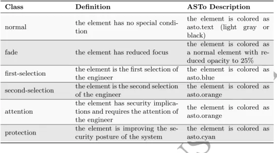
The Apparatus Framework does not impose a specific way of representing models in a visual manner. However, a default front-end representation of Apparatusmodels is used by ASTo along with a defined a set of class descriptions. The visualization of graphs ASTo uses a customizable color palette on the notation classes. Colors values are prefixed withasto.and the name of the color. The notation classes are presented in Tab. 1.
An example of how classes are applied dynamically in ASTo, following the threat validation described above, as an algorithm is the following:
1. The classfade is applied to all elements in the graph. 2. The classattentionis applied to all threat concepts. 3. The classprotectionis applied to all constraint concepts. 4. The classnormal is applied to all mitigate relationships.
ACCEPTED MANUSCRIPT
Table 1 Notation Classes of theApparatusFramework
Class Definition ASTo Description
normal the element has no special condi-tion the element is colored asasto.text (light gray or black)
fade the element has reduced focus the element is colored asa normal element with re-duced opacity to 25% first-selection the element is the first selection ofthe engineer the element is colored asasto.blue second-selection the element is the second selectionof the engineer the element is colored asasto.orange attention the element has security implica-tions and requires the attention of
the engineer
the element is colored as asto.orange
protection the element is improving the se-curity posture of the system the element is colored asasto.cyan
By using that algorithm we focus the attention of the engineer on the elements of the model that are important during the threat validation process.
3.4 Transition rules between the different engineering phases
During the security analysis workflow, a security engineer may have to create models of the same system in both the design phase and the implementation phase. This may be done during the normal development process of a system, from its design to implemen-tation. In such a case an engineer will be able to use an existing design phase model it to transition to the implementation phase. In that way, engineers can reuse existing models to reduce the development process.
While the normal engineering workflow would progress from the design to the im-plementation phase, certain use cases would require for an engineer to transition from the implementation phase to the design phase. An example of such a use case is the development of a redevelopment of an existing IoT system. Redevelopment of a system is more easily made in the design phase, where an engineer can abstract its components. But if there is an existing implementation phase model, the process of transitioning to the design phase may not be considered cost-effective. In theApparatusFramework an engineer can model the existing IoT system as an implementation phase model. Then the implementation to design transition rules can be applied to generate a design phase of the system.
To facilitate the transition process between the two engineering phases, we define a structured approach that can be used to transition between a design phase model and an implementation phase model and vice versa.
3.4.1 Design to Implementation phase transition rules
To transition a model from the design to the implementation phase we perform the following procedure:
ACCEPTED MANUSCRIPT
1. Micronet concepts gain thestate attribute.
2. Device concepts gain thelayer, type, service, input, output, update attributes. 3. Design concept Devices that have theconnect relationship with other Devices,
re-place that connection with the concept of Network Connection. 4. Application concepts gain theversion, update attributes. 5. Information concepts gain thelocationattribute.
6. All other concepts remain the same.
3.4.2 Implementation to Design transition rules
To transition between an implementation phase model to a design phase model, we perform the procedure stated above in reverse:
1. Remove the attributes the attributes from the concepts that have been outlined during the steps above.
2. Remove the concepts of Mechanism. 3. Remove the concepts of Vulnerability.
Both procedures have been implemented in ASTo, where an engineer can perform them in an automated manner.
4 Illustrative example of security analysis using the Apparatus Framework To illustrate how the proposed framework can be used we will perform a concise security analysis on a smart city IoT application. We will model a subset of a smart public transport system. The system in the example does not represent a real-life smart public transport system. It is designed to showcase the certain features of the Apparatus
Framework with the minimum numbers of components in order to provide a precise and clear application.
During the example, we will begin our security analysis from the design phase. The city already has a certain infrastructure for public transport in place. Those components will act as the initial components of the system. The hardware and software components of the system are:
1. A central processing unit that will act as the focal point of processing for the entire smart public system.
2. A microcomputer, such as a raspberry pi, on board the bus. The microcomputer acts as a processing unit for the bus’s internal operations.
3. A router on board the bust. The router will provide a Wi-Fi network to the bus’s passengers and other network connectivity to the bus’s system through an LTE connection.
4. Smart sensors on bus stops. They will exchange traffic and route information between the buses and the central processing unit.
5. The smartphones of passengers that will use the dedicated mobile application of the smart public transport system.
Based on the components of the system, we can create the design phase model using the network and social modules of theApparatusFramework, as shown in Fig. 3.
The stakeholders of the system, in this case, the users of the transportation system. The smart public transport will have the following security requirements that are elicited from the stakeholders:
ACCEPTED MANUSCRIPT
Fig. 3 Design phase network and social system model
1. SR1:passengers should not be able to tamper with bus’s hardware systems. 2. SR2:passengers personal data should not be able to be exposed without
authoriza-tion through the bus’s resources.
The requirements stated above will form the core of our security analysis. We will use them to identify threats, constraints and the assets of the system. While in Fig. 3 we modeled to the whole system, in the interest of space, we are going to limit our security analysis only on the domain of the bus.
The security analysis in Apparatus is asset-centric. The initial step is to identify the assets of the system. Based on SR1 and S2 we identify the following Assets in the system.
1. A1:the physical aspect of the bus’s microcomputer. 2. A2:the personal information of the passengers.
The second step in the security analysis is to model the threats of the system, based on the identified asset. A threat (T1) that impacts the A1 is a Denial of Service (DoS) attack that originates from a passenger with malicious intent. The attacker physically damages the device, thus making its resources unavailable to legitimate users. A threat (T2) that impacts the A2 is social engineering attack aiming to obtain a passenger’s personal data. That attack is originating from external connections. In this case, the Internet. To summarize, the threats on the systems are:
1. T1:physically attack the microcomputer to perform a DoS attack.
2. T2: exploit the smart transport application to obtain passengers’ personal data through social engineering.
ACCEPTED MANUSCRIPT
Once threats have been modeled, the next step of the security analysis is to proposes system Constraints. We propose the following Constraints to mitigate the identified threats T1 and T2.
1. C1:physically protect the microcomputer to mitigate T1.
2. C2: smart transport application must notify the user every time request for his personal information is made from an untrusted source, to mitigate T2.
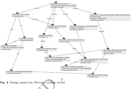
The Fig. 4 presents the Micronet system model of the bus, including the security components.
Fig. 4 Design phase bus Micronet system model
When the design phase security analysis is completed, the next step is to perform a security analysis during the implementation phase. We will apply the Design to Imple-mentation rules of the Apparatus framework. In this particular example, the transfor-mation process is automated using the ASTo software application.
In the implementation phase a number of components, such as the Device, Applica-tion, and Micronet obtain additional attributes, to better represent the more detailed information we have. We can determine those attributes using information provided by the stakeholders of the system. Alternatively, we can apply information gathering tech-niques common in information security in the existing implementation of the system. Such techniques include scanning the existing network range for active devices, active ports, and known services.
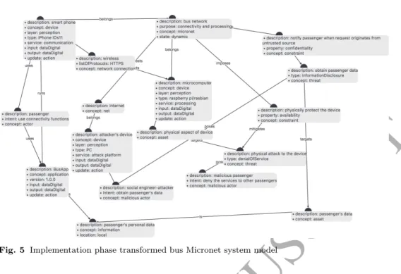
After the transformation rules are applied and the stakeholders provide us with the necessary information we create an implementation phase system model as shown in Fig. 5.
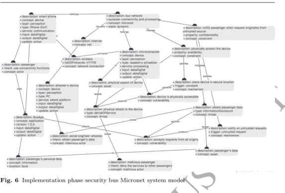
The implementation has two additional components that better illustrate the se-curity posture of a system. Those are the Mechanism and the Vulnerability. T1 is the threat of physically attacking a device. In the case of the smart public transportation, the Vulnerability (V1) is that the device (microcomputer) is physically accessible to
ACCEPTED MANUSCRIPT
Fig. 5 Implementation phase transformed bus Micronet system model
actors and malicious actors alike. To protect the system from V1, we propose that the microcomputer should be located in a secure location. The T2 is the threat of a malicious attacker exploiting the smart transport application to obtain the personal information of the passengers. The application’s version is 1.0.0. The stakeholders inform us that the application does not sanitize requests based on their origin. Meaning that requests are treated the same whether they originated from trusted or untrusted sources. To protect the system, we propose that passengers should be notified and manually accept requests originating from untrusted sources, as a Mechanism (M2).
The implementation system model that includes the final version of the security analysis is shown in Fig. 6.
The example is not an extensive security analysis of the proposed system. It was designed to demonstrate certain aspects of the Framework. Even a small system, such as the one presented, can generate a graph with hundreds of nodes and complex rela-tionships.
A complete security example is out of the scope of this journal, but we will provide some additional examples of security analysis that can be performed based on the exist-ing information encoded in the system models. The software and hardware components of the system have the attributeupdate with the valueaction. Theaction requires that an actor must manually perform the update on the device or application. That means that when a new exploit for the particular component is made discovered, the system is vulnerable until an actor performs the update. Depending on the severity of the ex-ploit, the system could include mechanisms that treat the exploitable components as compromised Devices until they are updated.
Other attributes of the modeling language are used to identify the security posture of the system. For example, the concept of Network connection attribute of Description portrays whether the connection uses a wireless or a wired medium. As a general rule, wireless connections are more susceptible to repudiation and information disclosure attacks, than wired connections. The connections medium will affect the mechanisms that a security engineer will propose.
ACCEPTED MANUSCRIPT
Fig. 6 Implementation phase security bus Micronet system model
The Micronet of the bus in the example above has the value of the State attribute as dynamic. That means that the components of the Micronet are moving in physical space. To retain their connection to the rest, the components frequently change their gateway endpoints. In the instance of the Bus Micronet, the router of the bus provides Internet connectivity to the other components through LTE. The LTE infrastructure is not under the control domain of the security engineer. Dynamic systems require different mechanisms than a static system. In a static system, an engineer can deploy certain perimeter mechanisms such as a back-end firewall or Intrusion Detection system. On the other hand, the same mechanisms are less useful in a dynamic system.
The layer attribute of the Device concept can be used to infer both the conceptual use of the Device and its inhered physical location. Devices that belong to the application layer are usually processing servers that either are located in the cloud or in physically secure location. Devices that belong to the perception layer are usually located in close proximity to actors. They represent sensors and end-point devices. A Constraint that can be proposed in a Micronet, is that all Devices of the system that have thelayer: perception, should be physically protected. Since Devices belonging to the perception layer of IoT offer physical access to both actors and malicious actors. They are vulnerable to threats that require physical access.
5 Conclusion
This paper starts by illustrating the importance of proposing a novel modeling approach to facilitate security analysis and reasoning in IoT systems on smart city applications. Given the dynamic nature of IoT systems and their vast applications, it is expected that their security specifications will need to mitigate their vast attack surface. To enable the security analysis of such systems, we presented a number of components of the Apparatus Framework. The components where a set of modular metamodels to express IoT systems along with security and social constructs. The first metamodel is used to
ACCEPTED MANUSCRIPT
express an IoT system during the design phase, while the second metamodel is used to express an IoT during the implementation phase. To facilitate analysis during the two engineering phases, we proposed transformation rules that can be applied to convert model between them.
To illustrate the use of the proposed modeling approach we performed a small-scale security analysis on a smart city application. The smart city application consisted of a smart public transport system that contained different hardware and software components along with different stakeholders.
The security analysis and visualization of the system were performed using a software application namedASTo that facilitates the security analysis of IoT systems. ASTo is developed to support the Apparatus Framework.
IoT system modeling has certain challenges. Once such challenge is scalability of models that are expected to be composed of thousands of nodes. The concepts of Mi-cronet and Net were developed to reduce “noise” in visual models by grouping together and abstracting systems based on common goals and functionality. Instead of analyzing systems composed of thousands of identical nodes, security engineers can group such nodes into Mirconets and Net. When the security analysis of the individual nodes inside a Micronet or a Net ,needs to take place, an engineer can only view and analyze those nodes.
A limitation of the current state of the Framework, is that it requires domain specific expertise from a variety of the stakeholders in order to create models. The creation of a model requires knowledge of the network architecture of a system, the perceived assets of the system as well as the user-system interaction. Future work aims to introduce a number of automated and semi-automated processes to creating models and deducing security issues. This approach will bring to the attention of a security engineer secu-rity issues based on the current topology of a model and best practices. The aim is to automate certain aspects of security analysis, such as vulnerability identification and model generation, by providing additional information to a security engineer. Model generation can be automated using network capture files or even textual descriptions of existing systems. Using that approach security engineers will be encouraged to ex-periment with different system configurations and their effects on the overall system’s security posture. A future publication aims to present our findings from a large-scale study, where security engineers, not associated with the development of the Framework, apply it to real-life IoT systems.
References
1. ITU: Global standards initiative on internet of things recommendation itu-t y.2060 (2012) 2. Miorandi, D., Sicari, S., Pellegrini, F.D., Chlamtac, I.: Internet of things: Vision, applications
and research challenges. Ad Hoc Networks10(7) (2012) 1497 – 1516
3. Gubbi, J., Buyya, R., Marusic, S., Palaniswami, M.: Internet of things (iot): A vision, architec-tural elements, and future directions. Future Generation Computer Systems29(7) (2013) 1645 – 1660 Including Special sections: Cyber-enabled Distributed Computing for Ubiquitous Cloud and Network Services & Cloud Computing and Scientific Applications — Big Data, Scalable Analytics, and Beyond.
4. Mavropoulos, O., Mouratidis, H., Fish, A., Panaousis, E., Kalloniatis, C.: Apparatus: Reasoning about security requirements in the internet of things. Advanced Information Systems Engineering Workshops249(2016) 219–230
5. Mavropoulos, O., Mouratidis, H., Fish, A., Panaousis, E.: Asto: A tool for security analysis of iot systems. In: Software Engineering Research, Management and Applications (SERA), 2017 IEEE 15th International Conference on, IEEE (2017) 395–400
6. Mavropoulos, O., Mouratidis, H., Fish, A., Panaousis, E., Kalloniatis, C.: Aconceptual model to support security analysis in the internet of things. Computer Science and Information Systems 14(2) (2017) 557–578
ACCEPTED MANUSCRIPT
7. Thiago, T., Sara, H., Issarny, V., Georgantas, N. In: Service Oriented Middleware for the Internet of Things: A Perspective. Springer Berlin Heidelberg, Berlin, Heidelberg (2011) 220–229 8. Hachem, S., Teixeira, T., Issarny, V.: Ontologies for the internet of things. In: Proceedings of
the 8th Middleware Doctoral Symposium. MDS ’11, New York, NY, USA, ACM (2011) 3:1–3:6 9. Russomanno, D.J., Kothari, C., Thomas, O.: Sensor ontologies: from shallow to deep models. In: System Theory, 2005. SSST’05. Proceedings of the Thirty-Seventh Southeastern Symposium on, IEEE (2005) 107–112
10. Botts, M., Robin, A.: Opengis sensor model language (sensorml) implementation specification. OpenGIS Implementation Specification OGC7(000) (2007)
11. Alam, S., Chowdhury, M.M., Noll, J.: Senaas: An event-driven sensor virtualization approach for internet of things cloud. In: Networked Embedded Systems for Enterprise Applications (NESEA), 2010 IEEE International Conference on, IEEE (2010) 1–6
12. De, S., Barnaghi, P., Bauer, M., Meissner, S.: Service modelling for the internet of things. In: Computer Science and Information Systems (FedCSIS), 2011 Federated Conference on, IEEE (2011) 949–955
13. Villalonga, C.: D2. 5 adaptive and scalable context composition and processing. Public SENSEI Deliverable (2010)
14. Alam, S., Chowdhury, M.M., Noll, J.: Interoperability of security-enabled internet of things. Wireless Personal Communications61(3) (2011) 567–586
15. Ikram, A., Anjum, A., Hill, R., Antonopoulos, N., Liu, L., Sotiriadis, S.: Approaching the internet of things (iot): a modelling, analysis and abstraction framework. Concurrency and Computation: Practice and Experience27(8) (2015) 1966–1984
16. Laghari, S., Niazi, M.A.: Modeling the internet of things, self-organizing and other complex adaptive communication networks: a cognitive agent-based computing approach. PloS one11(1) (2016) e0146760
17. Mouratidis, H., Giorgini, P.: Secure tropos: a security-oriented extension of the tropos method-ology. International Journal of Software Engineering and Knowledge Engineering 17(2007) 285–309
18. Haley, C., Laney, R., Moffett, J., Nuseibeh, B.: Security requirements engineering: A framework for representation and analysis. IEEE Transactions on Software Engineering34(1) (2008) 133– 153
19. Giorgini, P., Mouratidis, H.: Secure tropos: A security-oriented extension of the tropos method-ology. International Journal of Software Engineering and Knowledge Engineering17(02) (2011) 285–309
20. Shepherd, C., Petitcolas, F.A., Akram, R.N., Markantonakis, K.: An exploratory analysis of the security risks of the internet of things in finance. In: International Conference on Trust and Privacy in Digital Business, Springer (2017) 164–179
21. Shostack, A.: Threat modeling: Designing for security. John Wiley & Sons, Indianapolis, IN (2014)
22. Andress, J.: The basics of information security: Understanding the fundamentals of Infosec in theory and practice. Syngress Media,U.S., United States (2014)
23. Yang, Z., Yue, Y., Yang, Y., Peng, Y., Wang, X., Liu, W.: Study and application on the architecture and key technologies for iot. In: 2011 International Conference on Multimedia Technology, Hangzhou, Institute of Electrical & Electronics Engineers (IEEE) (2011) 747 – 751 24. Miao, W., Ting-lie, L., Fei-Yang, L., Ling, S., Hui-Ying, D.: Research on the architecture of
internet of things. Volume 5., Chengdu, IEEE (2010) 484–5
25. Atzori, L., Iera, A., Morabito, G.: The internet of things: A survey. Computer Networks54(15) (2010) 2787–2805
26. Lu, T., Neng, W.: Future internet: The internet of things. Volume 5., Chengdu, IEEE (08 2010) 376–5
27. Krco, S., Pokric, B., Carrez, F.: Designing iot architecture(s): A european perspective. In: 2014 IEEE World Forum on Internet of Things (WF-IoT), Seoul, Institute of Electrical & Electronics Engineers (IEEE) (2014) 79 – 84
28. Kurose, J.F., Ross, K.W.: Computer networking: A top-down approach. 6 edn. Addison-Wesley Educational Publishers, Boston (02 2012)
29. Mouratidis, H., Argyropoulos, N., Shei, S.: Security requirements engineering for cloud comput-ing: The secure tropos approach. Domain-Specific Conceptual Modeling (2016) 357–380 30. Vasilevskiy, A., Morin, B., Haugen, O., Evensen, P.: Agile development of home automation
system with thingml. In: 2016 IEEE 14th International Conference on Industrial Informatics (INDIN). (2016)