UNITEC New Zealand
A thesis submitted in partial fulfilment of the requirements for the
degree in Master of Computing
P
Pe
er
rf
fo
o
rm
r
ma
an
nc
ce
e
e
ev
va
al
l
u
u
at
a
t
i
i
o
o
n
n
o
o
f
f
I
IP
P
ve
v
er
rs
si
i
o
o
n
n
4
4
an
a
n
d
d
I
IP
P
v
v
e
e
r
r
s
s
i
i
o
o
n
n
6
6
t
t
r
r
a
a
n
n
s
s
i
i
t
t
i
i
o
o
n
n
m
m
e
e
c
c
h
h
a
a
n
n
i
i
s
s
m
m
s
s
o
o
n
n
v
v
a
a
r
r
i
i
o
o
u
u
s
s
o
o
pe
p
er
ra
at
t
i
i
ng
n
g
s
sy
ys
st
t
em
e
ms
s
Abstract
Internet Protocol version 6 is the Next Generation Internet Protocol developed by Internet Engineering Task Force to substitute the current Internet Protocol version 4. The reason of this substitution is the exhaustion of IPv4 address space. However, it is not possible to migrate from IPv4 to IPv6 in a short period due to the size and complexity of the Internet infrastructure. Thus, IPv4 will coexist with IPv6 for a long time before the entire Internet infrastructure can fully migrate to IPv6. IETF Next Generation Transition Working Group (NGtrans) developed IPv4/IPv6 transition mechanisms that help IPv4 and IPv6 coexist on the Internet during the migration period.
The purpose of this research is to evaluate performance of two tunnelling mechanisms (Configured Tunnel and 6to4 tunnelling mechanisms) operate on four selected operating systems (Windows Server 2003, Windows Server 2008, Ubuntu 9.10, and Fedora Core 11). This performance measurement research examined on two types of transmission protocols namely UDP (User Datagram Protocol) and TCP (Transmission Control Protocol). The result of this research focused on four metrics such as throughput, delay, jitter, and CPU utilization. The experiments conducted using different payload sizes, ranging from 64 bytes to 1536 bytes.
Results of this experimental research indicated that, Configured Tunnel and 6to4 perform differently on Windows Server 2003, Windows Server 2008, Ubuntu 9.10, and Fedora 11. By using TCP as transport protocol, Configured Tunnel on Fedora 11 produced the highest throughput. However, it also produced a very high delay as compared to Ubuntu 9.10, Windows Server 2003, and Windows Server 2008.On the other hand, after measuring UDP traffic, the results indicated that 6to4 on Ubuntu 9.10 produced the highest throughput with the lowest delay, which designate as the best choice for video and voice traffics.
Acknowledgements
I would like to acknowledge for all help and support that I received from postgraduate programmes director Donald Joyce. I would like to acknowledge a special thanks to my supervisors Shaneel Narayan and Hira Sathu for their time, ideas, guidance and support, throughout this research study.
My family is a big part of this achievement. I would like to thank you to all my family members who have given me courage and support throughput the duration of my Master of Computing study and particularly during the period of this research.
Without people mentioned above, I would not have completed my thesis and Master of Computing from Unitec.
Table of Contents
ABSTRACT ... I ACKNOWLEDGEMENTS ... II LIST OF TABLES ... VI LIST OF FIGURES ... VII
1 CHAPTER 1: INTRODUCTION... 1
1.1 STRUCTURE OF THE REPORT ... 2
2 CHAPTER 2: LITERATURE REVIEWS... 3
2.1 INTERNET PROTOCOL VERSION 4(IPV4)... 3
2.1.1 Consequences of the limited IPv4 address space ... 4
2.2 INTERNET PROTOCOL VERSION 6(IPV6)... 5
2.3 COMPARISON OF IPV4 AND IPV6 FEATURES ... 7
2.4 TRANSITION MECHANISMS... 9
2.4.1 Dual Stack ... 9
2.4.2 Configured Tunnel ... 10
2.4.3 6over4 Tunnelling Mechanism... 11
2.4.4 6to4 Tunnelling Mechanism ... 11
2.4.5 Intra-Site Automatic Tunnel Addressing Protocol ... 12
2.4.6 Network Address Translation-Protocol Translation ... 13
2.5 PERFORMANCE METRICS ... 14
2.5.1 Throughput ... 14
2.5.2 Delay ... 14
2.5.3 Jitter ... 14
2.5.4 CPU Utilization... 15
2.6 EVALUATION OF PERFORMANCE MEASUREMENT TOOLS ... 15
2.6.1 iPerf ... 15
2.6.2 Netperf ... 16
2.6.3 IP Traffic ... 17
2.6.4 Distributed Internet Traffic Generator (D-ITG)... 18
2.6.5 Selection of Tool ... 18 2.7 RELATED STUDIES ... 19 2.7.1 Study 1 ... 19 2.7.2 Study 2 ... 22 2.7.3 Study 3 ... 24 2.7.4 Study 4 ... 29 2.7.5 Study 5 ... 31 2.8 IDENTIFIED GAPS ... 34 2.9 LITERATURE MAP ... 36 2.10 CHAPTER SUMMARY ... 37
3 CHAPTER 3: METHODOLOGY ... 38
3.1 HYPOTHESIS ... 38
3.2 METHOD USED FOR STUDY ... 38
3.3 DATA COLLECTION ... 39
3.4 LITERATURE REVIEW PROCESS ... 40
3.5 EXPERIMENTAL DATA GATHERING PROCESS ... 40
3.6 CHAPTER SUMMARY ... 42
4 CHAPTER 4: EXPERIMENTAL DESIGN ... 43
4.1 HARDWARE SPECIFICATIONS ... 43
4.2 SOFTWARE SPECIFICATION ... 44
4.3 NETWORK DESIGN ... 44
4.4 NETWORK SETUP AND CONFIGURATION... 45
4.4.1 Configured Tunnel mechanism on Windows Server 2003 ... 45
4.4.2 6to4 mechanism on Windows Server 2003 ... 47
4.4.3 Configured Tunnel mechanism on Windows Server 2008 ... 48
4.4.4 6to4 mechanism on Windows Server 2008 ... 49
4.4.5 Configured Tunnel mechanism on Ubuntu 9.10... 50
4.4.6 6to4 mechanism on Ubuntu 9.10 ... 51
4.4.7 Configured Tunnel mechanism on Fedora Core 11 ... 52
4.4.8 6to4 mechanism on Fedora Core 11 ... 53
4.5 CHAPTER SUMMARY ... 54
5 CHAPTER 5: DATA ANALYSIS ... 55
5.1 TCPDATA ANALYSIS ... 55
5.1.1 TCP Throughput ... 55
5.1.2 TCP Jitter... 65
5.1.3 TCP Delay... 66
5.1.4 TCP - Router1 CPU Utilization ... 67
5.1.5 TCP - Router2 CPU Utilization ... 69
5.2 UDPDATA ANALYSIS ... 70
5.2.1 UDP Throughput ... 70
5.2.2 UDP Jitter... 76
5.2.3 UDP Delay... 78
5.2.4 UDP Router1 CPU Utilization ... 79
5.2.5 UDP Router2 CPU Utilization ... 80
5.3 COMPARISON OF TCP AND UDP ... 81
5.3.1 UDP and TCP Throughput ... 81
5.3.2 UDP and TCP Jitter ... 83
5.3.3 UDP and TCP Delay ... 84
5.3.4 UDP and TCP Router 1 CPU Utilisation ... 85
5.3.5 UDP and TCP Router 2 CPU Utilisation ... 86
5.4 SUMMARY ... 86
6.1 DISCUSSION OF FINDINGS ... 87
6.1.1 TCP Performance ... 87
6.1.2 UDP Performance ... 89
6.1.3 UDP and TCP Comparison ... 90
6.1.4 Summary of Findings ... 90
6.2 FUTURE STUDY ... 92
7 CHAPTER 7: CONCLUSION ... 93
APPENDICES ... 95
APPENDIX A:TCPTHROUGHPUT RESULTS ... 95
APPENDIX B:TCPJITTER RESULTS ... 96
APPENDIX C:TCPDELAY RESULTS ... 97
APPENDIX D:ROUTER1-TCPCPUUTILISATION RESULTS ... 98
APPENDIX E:ROUTER2-TCPCPUUTILISATION RESULTS ... 99
APPENDIX F:UDPTHROUGHPUT RESULTS ... 100
APPENDIX G:UDPJITTER RESULTS ... 101
APPENDIX H:UDPDELAY RESULTS ... 102
APPENDIX I:ROUTER1-UDPCPUUTILISATION RESULTS... 103
APPENDIX J:ROUTER2-UDPCPUUTILISATION RESULTS ... 104
List of Tables
Table 2-1: Classes of IPv4 ... 3
Table 2-2: Internet host count history ... 4
Table 2-3: Comparison of IPv4 and IPv6 features... 8
Table 2-4: Hardware specifications ... 20
Table 2-5: The differences between BDMS and DSTM ... 23
Table 2-6: Comparisons of tunnel-based mechanisms ... 24
Table 2-7: TCP connection time ... 30
Table 2-8: Web client/Server simulation tests ... 31
Table 2-9: Parameters used in simulation cases ... 32
Table 2-10: Summary of related work... 34
List of Figures
Figure 2-1: Graph of the evolution of the Internet hosts ... 5
Figure 2-2: IPv4 and IPv6 headers (Sailan, Hassan, and Patel, 2009) ... 7
Figure 2-3: Dual IP Stacks ... 9
Figure 2-4: Configured Tunnel Network Infrastructure ... 10
Figure 2-5: 6to4 address architecture ... 11
Figure 2-6: 6to4 Network Infrastructure ... 12
Figure 2-7: NAT-PT Network Infrastructure ... 13
Figure 2-8: IPerf components... 16
Figure 2-9: ISATAP test-bed configuration (Visoottiviseth & Bureenok, 2008) ... 20
Figure 2-10: Configured Tunnel test-bed (Chen et al., 2004) ... 25
Figure 2-11: 6to4 Tunnel test-bed ... 26
Figure 2-12: Tunnel Broker test-bed (Chen et al., 2004) ... 26
Figure 2-13: Perfmon CPU performance monitoring tool... 28
Figure 2-14: Network Setup (Raicu & Zeadally, 2003) ... 29
Figure 2-15: Network Model ... 32
Figure 3-1: Sample D-ITG total result ... 41
Figure 3-2: Sample Line Chart ... 41
Figure 4-1: Network design ... 44
Figure 5-1: Configured Tunnel and 6to4 on Windows Server 2008 – TCP Throughput ... 55
Figure 5-2: Configured Tunnel and 6to4 on Windows Server 2003 – TCP Throughput ... 57
Figure 5-3: Configured Tunnel and 6to4 on Ubuntu 9.10 – TCP Throughput ... 58
Figure 5-4: Configured Tunnel and 6to4 on Fedora 11 – TCP Throughput ... 60
Figure 5-5: TCP Throughput (Mbps) ... 61
Figure 5-6: TCP Throughput from packet size 64 bytes to 128 bytes ... 62
Figure 5-7: TCP Throughput from packet size 128 bytes to 768 bytes... 62
Figure 5-8: TCP Throughput from packet size 768 bytes to 1536 bytes ... 64
Figure 5-9: TCP Jitter ... 65
Figure 5-10: TCP Delay ... 67
Figure 5-11: Router 1 - CPU Utilisation of TCP performance ... 68
Figure 5-12: Router 2 - CPU Utilisation of TCP performance ... 69
Figure 5-13: Configured Tunnel and 6to4 on Windows Server 2008 – UDP Throughput ... 71
Figure 5-14: Configured Tunnel and 6to4 on Windows Server 2003 - UDP Throughput ... 72
Figure 5-15: Configured Tunnel and 6to4 on Ubuntu - UDP Throughput ... 73
Figure 5-16: Configured Tunnel and 6to4 on Fedora 11 – UDP Throughput ... 74
Figure 5-17: UDP Throughput Result ... 75
Figure 5-18: UDP Jitter Result ... 77
Figure 5-19: UDP Average Delay Result ... 78
Figure 5-20: Router 1 – CPU Utilisation of TCP performance... 79
Figure 5-21: Router 2 – CPU Utilisation of TCP performance... 80
Figure 5-22: UDP and TCP Throughput Result... 81
Figure 5-23: UDP and TCP Jitter ... 83
Figure 5-24: UDP and TCP Delay ... 84
Figure 5-25: TCP and UDP Router 1 CPU Utilisation... 85
List of Abbreviation
ALG Application Layer Gateway ATM Asynchronous Transfer Mode BDMS Bi-Directional Mapping System BSD (Tools)
CLI Command Line Interface CPU Central Processing Unit
D-ITG Distributed Internet Traffic Generator DLPI (Tools)
DSTM Dual Stack Tunnelling Mechanism EED End-to-End Delay
IEEE Institute of Electrical and Electronic Engineer IETF Internet Engineering Task Force
IP Internet Protocol
IPv4 Internet Protocol Version 4 IPv6 Internet Protocol Version 6
ISATAP Intra-Site Automatic Tunnel Addressing Protocol ISDN Integrated Services Digital Network
LAN Local Area Network Mbps Megabit per second
MLD Multicast listener Discovery ms Millisecond
MTU Maximum Transmission Unit NAT Network Address Translation
NAT-PT Network Address Translation – Protocol Translator NGtrans Next Generation Transition Working Group
NIC Network Interface Card pps Packet per second RFC Request For Comment RTT Round Trip Time
TCP Transmission Control Protocol UDP User Datagram Protocol WAN Wide Area Network
1 Chapter 1: Introduction
This research focuses on the differences in network performance of various IP version 4 and IP version 6 transition mechanisms used over various Operating Systems.TCP/IP is a protocol suite that allow the Internet operate across geographical areas. IP is one of the protocols within TCP/IP protocol suite and this protocol was begun with version 4 which is known as Internet Protocol version 4 (IPV4). Internet Protocol is the standard protocol being used on the Internet which allows computers to be able to communicate in order to exchange information such as data, voice (VoIP), and video (Video conference). Internet Protocol version 4 (IPv4) is the current internet protocol that is widely used across the Internet, but in the near future, there exist issues like insufficient public Internet Protocol version 4 address space that does not allow the growth of the Internet. Nowadays, most of mobile devices are required to have an IP address to connect to the Internet which leads to high consumption of IP address. Internet Engineer Task Force has considered this issue and proposed a new version of Internet Protocol namely Internet Protocol Version 6 (IPv6).
Internet Protocol version 6 (IPv6) is the solution to the massive growth of the Internet due to the size of the address spaces. IPv6 addressing contains 128 bits binary value that provide 2^128 addresses. In the near future the current Internet Protocol version 4 (IPv4) will slowly migrate to Internet Protocol version 6 (IPv6). Sailan, Hassan, and Patel (2009) state that “Currently IPv6 network penetration is still low but it is expected to grow, while IPv4 address pool is projected by Regional Internet Registry to be exhausted by the end of 2011”. During the migration period there will be compatibility and interoperability issues relating to Internet Protocol version 4 (IPv4) and Internet Protocol version 6 (IPv6) because Internet Protocol version 6 (IPv6) is not backward compatible with Internet Protocol version 4 (IPv4). According to Govil, Govil, Kaur, and Kaur (2008):
The transition between IPv4 internet and IPv6 will be a long process as they are two completely separate protocols and it is impossible to switch the entire internet over to IPv6 over night. IPv6 is not backward compatible with IPv4 and IPv4 hosts and routers will not be able to deal directly with IPv6 traffic and vice-versa. As IPv4 and IPv6 will co-exist for a long time, this requires the transition and inter-operation mechanisms.
Migrating from IPv4 to IPv6 is a complicated task that cannot be done overnight. The size and complexity of the Internet cause this migration task to become enormously difficult and
time consuming. Next Generation Transition (NGtrans) proposed three main transition mechanisms that included dual stack, tunnelling, and translation (Waddington & Chang, 2002). These solution allow Internet Protocol version 4 (IPv4)to be able to coexist with Internet Protocol version 6 (IPv6) during the migration period.
The main target of this research is to study the performance of different transition mechanisms when implemented on various operating systems such as Windows server 2003, Windows server 2008, Linux Ubuntu 9.10, and Linux Fedora Core 11. The result of this research will discuss later in this report. Next section will be presenting the structure of this report.
1.1 Structure of the Report
There are total of seven chapters included in this report. Chapter one contains the introduction which briefly describes the overview of Internet Protocol version 4 (IPv4) and Internet Protocol version 6 (IPv6) and then leads to the transition mechanisms that overcome the issue of interoperation between IPv4 and IPv6 during the transition period. Chapter two presents the literature review, which contains information regarding IPv4, IPv6, transition mechanisms in detail and related studies conducted by different researchers.
Chapter three covers the research hypothesis, methodology used in this research, and the method of data collection. Chapter four covers details of experimental design covering the specification of hardware and software used in experiments, network diagram used to simulate the design of the network environment, and detail of network configuration. Chapter fivecovers the analysis of data gathered from the experiment. These data are presented in line charts with the discussion of each chart. Chapter six presents in depth discussion of the findings from this research. Chapter seven concludes this research. Next chapter will be introducing literature reviews.
2 Chapter 2: Literature Reviews
This chapter will be looking at IPv4 and IPv6 in detail in order to identify the problems, opportunities and the differences between the two versions of Internet Protocol. This chapter will be also looking at the coexistence of IPv4 and IPv6by analysing previous researches and finding gaps in the literature.
2.1 Internet Protocol Version 4 (IPv4)
IPv4 is the protocol used extensively on the Internet. All communication across the Internet currently relies on IPv4 protocol. In order to understand this protocol in more detail, first we need to look at the address scheme. IPv4 addressing contains four octets and each octet represents 8 bits of a binary number. The entire address space of IPv4 contains 32 bits of binary number, which mean IPv4 has 2^32 addresses that are equivalent to 4,294,967,296 different addresses. According to Cisco (2007-2009), IPv4 contains four classes of address, which shows in Table 2-1 below.
Class High Order Bits Start End
Class A 0 0.0.0.0 127.255.255.255
Class B 10 128.0.0.0 191.255.255.255
Class C 110 192.0.0.0 223.255.255.255
Multicast 1110 224.0.0.0 239.255.255.255
Table 2-1: Classes of IPv4
According to Jivesh, Govil, and Govil (2007) IPv4 address is written in dot decimal notation and it contains three types of address, which include unicast, broadcast, and multicast address.
2.1.1
Consequences of the limited IPv4 address space
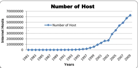
As discussed above, IPv4 contains 4,294,967,296 addresses. The number of hosts on the Internet increase dramatically every year, which has led to the exhaustion of IPv4 address space. Table 2-2 below was taken from Internet Systems Consortium (2001-2009), shows the increasing number of hosts on the Internet each year starting from year 1981 to year 2009.
Date Hosts Date Hosts Date Hosts
08/1981 213 07/1992 992,000 01/2000 72,398,092 05/1982 235 10/1992 1,136,000 07/2000 93,047,785 08/1983 562 01/1993 1,313,000 01/2001 109,574,429 10/1984 1,024 04/1993 1,486,000 07/2001 125,888,197 10/1985 1,961 07/1993 1,776,000 01/2002 147,344,723 02/1986 2,308 10/1993 2,056,000 07/2002 162,128,493 11/1986 5,089 01/1994 2,217,000 01/2003 171,638,297 12/1987 28,174 07/1994 3,212,000 01/2004 233,101,481 07/1988 33,000 10/1994 3,864,000 07/2004 285,139,107 10/1988 56,000 01/1995 4,852,000 01/2005 317,646,084 01/1989 80,000 07/1995 6,642,000 07/2005 353,284,187 07/1989 130,000 01/1996 9,472,000 01/2006 394,991,609 10/1989 159,000 07/1996 12,881,000 07/2006 439,286,364 10/1990 313,000 01/1997 16,146,000 01/2007 433,193,199 01/1991 376,000 07/1997 19,540,000 07/2007 489,774,269 07/1991 535,000 01/1998 29,670,000 01/2008 541,677,360 10/1991 617,000 07/1998 36.739,000 07/2008 570,937,778 01/1992 727,000 01/1999 43,230,000 01/2009 625,226,456 04/1992 890,000 07/1999 56,218,000
Table 2-2: Internet host count history
The table above shows that from 1981 to 1991 the numbers of hosts increased from 213 to 617,000 hosts, which mean within ten years there was an increase of 616,787 hosts. From 1991 to 2001, the numbers of host increased from 617,000 to 109,574,429 hosts, which
mean there were 109,574,429 hosts increased. From 2001 to 2009, the numbers of host increased from 109,574,429 to 625,226,456 hosts, which mean there was an exponential growth of 515,651,027 hosts. Figure 2-1 below shows the exponential growth of the Internet hosts which is according to the information from Table 2-2 above.
Figure 2-1: Graph of the evolution of the Internet hosts
Year after year, the numbers of hosts on the Internet keep increasing significantly due to the rapid grow of technology and number of people in large population countries began to access the Internet thus high demand of IP4 is bound to cause shortage of IPv4 address space (Grosse & Lakshman, 2003). Due to this reason, IETF proposed a solution to overcome the exhaustion of IPv4 address, which known as Internet Protocol Next Generation (IPng) or Internet Protocol version 6 (IPv6).Clear evidence from the above graph shows that, from the year 1997 to 2009 the growth of the Internet host has been asymptotic. Using the above graph it will not be very long for the existing IPv4 address space to be exhausted. Next section, discussed IPv6 the next generation Internet protocol that not only overcome address issues but also enhances other features.
2.2 Internet Protocol Version 6 (IPv6)
Internet Protocol version 6 (IPv6) is the new version of the Internet Protocol which was designed to overcome the shortcoming of IPv4. Green, Fiuczynski, & Jankiewicz (2006)
0 100000000 200000000 300000000 400000000 500000000 600000000 700000000 In te rn e t Ho s ts Years
Number of Host
Number of Hoststated that “IPv6 was designed to incorporate all of the patches, changes, and best practices developed from over twenty years of IPv4 Internet engineering into a new next-generation protocol to support the expansive growth of Internet communications and applications”. The development of IPv6 is not just resolving the address space but also provide better performance and improvement over IPv4 (Wang, Ye, & Li, 2005).It has been almost two decades that IETF NGtrans had proposed IPv6. According to Hiromi and Yoshifuji (2006) “IPv6 had been proposed at IETF as the next generation of Internet Protocol at early in the 1990s and it is now ready for practical use after trial phase”. Both IPv4 and IPv6 have different addressing format, as IPv4 addressing format is written in decimal notation and IPv6 addressing format is written in hexadecimal notation(Govil& Govil, 2007).IPv6supports unicast, anycast, and multicast address. On the other hand, IPv4 support unicast, anycast, and broadcast address.
Broadcast address of IPv4 is not available in IPv6 as stated in RFC2372 (1998) that “The function of broadcast addresses in IPv6 is being superseded by multicast addresses”. IPv6 contains number of advantages over IPv4.IPv6 is the solution to the exhaustion of IPv4 address. Eventually, IPv4 public addresses will be exhausted due to the limitation of the available address space. As a result, IETF developed IPv6 is the solution to this problem due to its larger address space. In addition to this scalability, IPv6 allows the Internet to grow efficiently, the detail of which have been mentioned in this document. Prior to the introduction of IPv6, Network Address Translation (NAT)and Classless Interdomain Routing (CIDR) were introduced as a temporary solution to the shortage of IPv4 address that allows all the hosts within an intranet site to be able to use the same private IP address range as other intranet sites around the globe.
Currently, address space use in private network and address space use in public network are disjointed which means that the communication between private network and public network is not possible without the use of Network Address Translation (NAT). After migrating to IPv6, disjointed address space will be resolved. At current stage home and enterprise networks are using Internet gateway devices such as ADSL modem or router to connect to the Internet. Each of these devices require having a public IPv4 address that is dynamically or statically allocated by the ISP while private IPv4 addresses are assigned to host devices. When IPv6 is fully established, both home and enterprise networks will be using global IPv6 address, which currently known in IPv4as public IP address. IPv6 has more efficient forwarding mechanism than IPv4 due to the 40 bytes fixed header size that allows routers to make faster decisions in forwarding IPv6 packets(Davies, 2008a).
There are number of advantages that IPv6 has over IPv4. Next section will discuss in detail the differences between these two protocols.
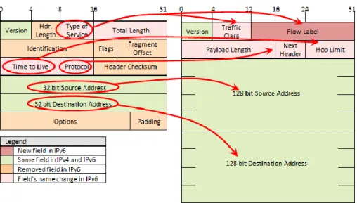
2.3 Comparison of IPv4 and IPv6 features
IPv6 packet header has fewer fields when compare to IPv4 header. IPv4 contains fourteen header fields whileIPv6 has eight header fields. However, the size of IPv6 header is double the size of IPv4 header, which means the difference between these two protocols’ headers is 20 bytes. This is due to the length of source and destination IPv6 address in IPv6 header fields (Davies, 2008a). There are changes in IPv6 header as compared to IPv4 header:
The Header Length field in IPv4 header is not present in IPv6.
Type of Service field in IPv4 header changed to Traffic Class and Flow Label field
in IPv6.
Source address and destination address of IPv4 contains 32 bit long for each field
whereas IPv6 contains 128 bit long for each field.
Time to Live field in IPv4 header changed to Hop Limit field in IPv6.
Protocol field in IPv4 header changed to Next Header field in IPv6.
IPv6 header does not contain Options and Padding fields.
Figure 2-2 below shows the differences between IPv4 header and IPv6 header.
Apart from IP header, IPv6 contain other features that are different from IPv4. Sailan, Hassan, and Patel (2009) stated that the differences between IPv4 and IPv6 features are as follow:
Features IPv4 IPv6
Address 32 bits 128 bits
Checksum in header Included No Checksum
Header includes options
Required Moved to IPv6 extension
headers
Quality of Services Differentiated Services Use traffic classes and flow labels
Fragmentation Done by routers and source
node
Only by the source node
IP configuration Manually or DHCP Auto-configuration or DHCP
IPsec support Optional Required
Transmission type Unicast, Multicast, and broadcast
Uses unicast, multicast, and anycast (Broadcast dropped) Address Resolution
Protocol (ARP)
Use to resolve an IPv4 address
Replaced with Multicast listener Discovery (MLD) Domain name service
(DNS)
Use host address (A) resource records
Use host address (AAAA) resource records
Mobility Use Mobile IPv4 (MIPv4) MIPv6 with faster handover,
routing and hierarchical mobility
Table 2-3: Comparison of IPv4 and IPv6 features
According to Table 2-3 above, IPv6 introduces enhanced features over IPv4. The address space in IPv6 is larger than IPv4, which helps solving the shortage of IPv4 address. This is the main feature that IETF introduced in IPv6. IPv6 contains built-in support for Quality of Service, which is an ideal solution for voice and video traffics.
IPv6 supports address auto-configuration and DHCPv6 that include stateless and stateful configuration. IPv6 designed to support mobility as it provides faster handover and routing. All these enhanced features, which make IPv6 as a successor over IPv4. However, IPv6 is not backward compatible with IPv4, which creates difficulties while both protocols coexist during transition period. Transition mechanisms are the tools that help resolving coexistence
2.4 Transition Mechanisms
The design of IPv6 shows that this new version of internet protocol was not designed to be backward compatible with IPv4, which mean IPv4 host is only capable of sending IPv4 packets to other IPv4 hosts, and the same applies to IPv6 host, which is only capable of sending IPv6 packets to other IPv6 hosts. Interoperation is a major issue when both protocols coexist on the Internet. To overcome the coexisting and incompatibility issue, Internet Engineering Task Force NGtrans designed and developed IPv4/IPv6 transition mechanisms to enable transition period to progress without any major issue. IPv4/IPv6 transition mechanisms allow IPv4 andIPv6 to coexist on the Internet. The coexistence of these two internet protocols can last for many years. Before conducting performance measurement on transition mechanisms, it is important to understand the theory behind each transition mechanism comprehensively. The following sections describe each transition mechanism in detail.
2.4.1
Dual Stack
Dual Stack is straightforward and simple configuration transition mechanism. Dual Stack requires operating systems to support both IPv4 and IPv6 which means both IPv4 and IPv6 are enabled on a single network interface card. A device with both IPv4 and IPv6 enabled known as IPv6/IPv4 node, which has the ability to send IPv4 or IPv6 packets to IPv4-only or IPv6-only node and receive IPv4 or IPv6 packets from IPv4-only or IPv6-only node. According to RFC2893 (2000) “IPv6/IPv4 nodes can directly interoperate with IPv4 nodes using IPv4 packets, and also directly interoperate with IPv6 nodes using IPv6 packets.” The following diagram shows the architecture of Dual IP Stacks, which was adapted from Mark & Miller (2000a): Application Layer Application Layer IPv6 Application Layer IPv4 Application Layer Application Layer IPv6 Application Layer Application Layer Application Layer IPv4 Application Layer Dual IP Stacks Node
IPv6 Node IPv4 Node
In order to communicate with both IPv4 node and IPv6 node, Dual IP Stacks node requires to have both IPv4 and IPv6 addresses to manually assignor assign by Dynamic Host Configuration Protocol (DHCP). Additionally, Dual IP Stacks node must support the record of DNS for IPv4 and DNS for IPv6 (Mark & Miller, 2000a). Configured Tunnel will discuss next.
2.4.2
Configured Tunnel
Configured Tunnel is a manual configured tunnelling mechanism, which enables two or more IPv6 networks to communicate across IPv4 routing infrastructure through a tunnel. According to Mark & Miller (2000a), “Configured Tunnelling is defined as IPv6-over-IPv4 tunnelling where the IPv4 tunnel endpoint address is determined by configuration information on the encapsulating node. The tunnel can be either unidirectional or bidirectional. Bidirectional Configured Tunnels behave as virtual point-to-point link.” The following Figure 2-4 shows the implementation of Configured Tunnel network infrastructure.
Configured-Tunnel
IPv6 Island IPv6 Island
IPv4 Cloud IPv6 node IPv6 node Configured-Tunnel endpoint Router Configured-Tunnel endpoint Router IPv6 node IPv6 node
External NIC External NIC
Figure 2-4: Configured Tunnel Network Infrastructure
This tunnelling mechanism requires configuring each tunnel endpoint routers manually in order to deliver IPv6 across IPv4 infrastructure. Each tunnel endpoint router contains two network interface cards with the internal network interface cards configured with IPv6 address and external network interface card configured with IPv4 address. IPv6 address is configured on the tunnel endpoint interface. Next section will discuss 6over4 tunnelling mechanisms.
2.4.3
6over4 Tunnelling Mechanism
6over4 is an automatic tunnelling mechanism that allows interconnection between isolated IPv6 Islands within IPv4 Ocean. 6over4 requires dual stack enabled on the external interface network card with a globally routable IPv4 address in order to connect to the IPv4 internet (Blanchet & Parent, 2000).6to4 tunnelling mechanism will discuss below.
2.4.4
6to4 Tunnelling Mechanism
According to Davies (2008a) “6to4 is an address assignment and router-to-router, host-to-router, and router-to-host automatic tunnel technology that is used to provide unicast IPv6 connectivity between IPv6 sites and hosts across the IPv4 Internet”. Figure 2-5 below show the architecture of 6to4 address adopted from Davies (2008a).
2002 WWXX:YYZZ Subnet ID Interface ID
16 bits 32 bits 16 bits 64 bits
Figure 2-5: 6to4 address architecture
As IPv6 packet arrives at 6to4 router, the encapsulation process is initiated by puttingIPv6 packet in IPv4 packet in order to transmit across IPv4 Internet infrastructure. Source and destination IPv4 address is specified with IPv4 header and the body of IPv4 packet contain IPv6 header and payload as stated in RFC3056 (2001).6to4 packet is travelling across 6to4 tunnelling established by 6to4 routers which also known as tunnelling endpoints. As the encapsulated packet arrives at the destination tunnelling end-point, 6to4 router performs de-capsulation process by removing IPv4 header and forward IPv6 packet through to IPv6 node. Figure 2-6 below shows the implementation of 6to4 network infrastructure:
6to4 Tunnel
IPv6 Island IPv6 Island
IPv4 Cloud IPv6 node IPv6 node Configured-Tunnel endpoint Router Configured-Tunnel endpoint Router IPv6 node IPv6 node
External NIC External NIC
Figure 2-6: 6to4 Network Infrastructure
6to4 has four components that have different functionality. Those four components are 6to4 host, 6to4 router, 6to4 host/router, and 6to4 relay. 6to4 host is a client computer, which does not have ability to perform 6to4 tunnelling across IPv4 Internet. 6to4 router has ability to perform 6to4 tunnelling across the Internet and forwarding 6to4 packet from 6to4 host in a site to another 6to4 host in another site across the Internet. 6to4 host/router has the ability perform tunnelling with 6to4 host/routers, 6to4 routers, and 6to4 relay but it does not have functionality to forward packet. Intra-Site Automatic Tunnel Addressing Protocol will discuss in next section.
2.4.5
Intra-Site Automatic Tunnel Addressing Protocol
Davies (2008a) defines ISATAP as below:
ISATAP is an address assignment and host-to-host, host-to-router, and router-to-host automatic tunnelling technology that provide unicast IPv6 connectivity between IPv6/IPv4 hosts across an IPv4 intranet. ISATAP hosts do not require any manual configuration and they can create ISATAP addresses using standard IPv6 address auto-configuration mechanisms.
ISATAP address will automatically assign to the ISATAP interface. ISATAP does not support router-to-router, which is the reason that this transition mechanism was not selected for this experimental research study. The drawback of ISATAP is the ability to implement across the Internet. ISATAP was not designed for the Internet users, but it was designed for the Intranet users (Hong, Ko, & Ryu, 2006). The discussion of Network Address Translation-Protocol Translation will discuss in next section.
2.4.6
Network Address Translation-Protocol Translation
NAT-PT is a translation mechanism, which functions as a translator for both IPv4 packet and IPv6 packets. The concept of NAT-PT is to translate IPv6 address to IPv4 address and vice versa (RFC 2766, 2000). The implementation of NAT-PT allows IPv4 network and IPv6 network to be able to communicate with one another via just a single PT server. NAT-PT is one of the ideal solutions, which helps IPv4 and IPv6 to coexist on the internet. Both IPv4 host and IPv6 host do not require having dual stack mode enable. However, each IPv4 and IPv6 network must have its own DNS server. Figure 2-7 below shows the implementation of NAT-PT network infrastructure.
Figure 2-7: NAT-PT Network Infrastructure
The operation of packet translation in NAT-PT is to convert IPv4 packet to IPv6 packet. According to Lee, Shin, and Kim (2004) “The source address of IPv6 header is replaced by an IPv6 address from IPv4 address pool and then the 96 bits prefix of destination IPv6 address is removed and last 4 bytes is used as IPv4 destination address”. NAT-PT functions as a translator server that holds global routable IPv4 address pool. The IPv4 address pool is used to dynamically allocate to the IPv6 node before the translation process is initiated across NAT-PT node. As soon as the translation process ends, IPv4 address assignment will end (Atwood, Das, Haddad, 2010). In general, NAT-PT is the IPv4 and IPv6 packet translator that sits in between IPv4 and IPv6 network and it translates IPv4 packet to IPv6 packet and vice-versa. The following section will discuss on different performance metrics used in this research.
NAT-PT
2.5 Performance Metrics
This section will be discussing the performance measurement metrics used in the performance testing of transition mechanisms. These metrics are throughput, jitter, delay, and CPU Utilisation.
2.5.1
Throughput
According to previous studies conducted by different researchers, throughput is one of the most common metrics used in the study of network performance evaluation. It helps to understand the amount of data travel across a network connection or between two network hosts. According to Blum (2003), “The throughput of a network represents the amount of network bandwidth available for a network application at any given moment, across the network links”. There are factors that can affect throughput performance such as the limitation of hardware processing power and network congestion or bottleneck due to the design of network topology. Megabits per second (Mbps) is the unit uses in throughput measurement.
2.5.2
Delay
According to Deveriya (2006) states that “Latency or delay, is the amount of time it takes a packet to traverse from source to destination”. Before measuring delay in an experiment, time synchronisation between sender and receiver is necessary. Make sure that sender and receiver nodes have exactly the same time settings.
2.5.3
Jitter
According to Cisco Systems (2001) “Jitter is the inter-packet delay variance; that is, the difference between inter-packet arrival and departure. Jitter is an important QoS metric for voice and video applications.” when multiple packets send across the network, the
2.5.4
CPU Utilization
CPU utilisation is the percentage amount of computer’s CPU resource taken during the processing of an application or a task. Higher percentage of CPU Utilisation shows that the computer optimally used CPU resources. This is not the case, which we should always be concerned about because if a computer shows higher CPU utilisation but it produces higher throughput, means the computer uses best possible resources in order to produce best throughput result. However, if the computer produces lower throughput, which is a point of concern, that hardware is not efficiently using the CPU resources. In this research study, all hardware requires to have identical specification in order to provide consistency between each node.
2.6 Evaluation of Performance Measurement Tools
There are varieties of performance tools available for measuring performance of various networks. Selecting the right tool for the experiment is critical because different tools have different functionalities. This section presents the review and discussion of four main network measurement tools. Below are the four main network measurement tools considered for the network performance measurement in this research study:
iPerf Netperf IP Traffic
D-ITG
2.6.1
iPerf
According to SourceForge (2009) iPerf is a network measurement tool developed by Distributed Applications Support Team (DAST). iPerf is open source software that can be used on both Windows and non-Windows operating systems. As stated by SourceForge (2009),iPerf is capable of evaluating UDP and TCP performance. iPerf is a measurement tool, which is capable of testing bandwidth, delay, jitter, and datagram loss.
iPerf is a command line tool, which means it requires command line interface such as command prompt tool for Microsoft operating systems and terminal tool for Linux. Two
components are required for iPerf to be able to execute. Those components are iPerf client and iPerf server. These two components are included in a single software package but different command is required to execute each component individually. Figure 2-8 below was adapted from openmaniak.com (2010) which shows the two components of iPerf.
Figure 2-8: IPerf components
iPerf client and iPerf server can either have the same or different operating system installed on the hardware. As per Schroder (2007) statement, “iPerf can run over the Internet as well as over LAN. It is invaluable for seeing what is happening over a WAN link, whether it is a nice expensive dedicated link or an OpenVPN tunnel over the Internet. The best way is to have iPerf on border router”. So iPerf is not just a measurement tool that can only use in the experiment test-bed but it can also use to test connection between two sites across WAN connection.
To connect iPerf client to iPerf server use the following command:
#iperf –c [iperf server IP address]
To connect execute iPerf server use the following command:
#iperf –s
According to openmaniak.com (2010), TCP and UDP port 5001 is the default port number that iPerf client uses to connect IPerf server.
2.6.2
Netperf
Netperf is another performance measurement tool that has the ability to measure the performance of different type of network. Netperf can be used on various platforms such as
Netperf is a benchmark tool that can be used to measure the performance of many different types of networking. It provides tests for both unidirectional throughput, and end-to-end latency. The environments currently measurable by Netperf include:
TCP and UDP via BSD Sockets for both IPv4 and IPv6. DLPI.
UNIX Domain Sockets. SCTP for both IPv4 and IPv6.
Netperf is a command line standard tool that has two elements which is known as Netclient and NetServer. As of June 2009, the latest version of Netperf is 2.4.5. Netperf is open
source software that can be downloaded from
http://www.netperf.org/netperf/DownloadNetperf.html.
2.6.3
IP Traffic
According to ZTI Telecom (2007), IP Traffic is commercial software developed by ZTI-Telecom in France. It is a data generation tool for IP networks. Data flows use TCP (Transmission Control Protocol), UDP (User Datagram Protocol) or ICMP (Internet Control Message Protocol) protocols.
This tool is an IP software-testing tool using the Microsoft Windows TCP/IP stack (Winsock2 interface). So it is independent of any transmission or telecom link and can use any transmission link managed by the Windows operating system: LAN (Ethernet, Token-ring, Hyper LAN, etc.), WLAN, WAN (modem, ISDN, ATM, satellite link, etc.), remote access, mobile or cellular networks.
IP Traffic is a graphic interface benchmark tool; it operates only on Microsoft platform such as Windows 98, Windows XP, Windows 2003, and newer version of Microsoft Windows operating system. Unlike the other three tools above, this performance tool is a commercial software; hence a licence is required to run this software after the 15-day-trial period expires. Like other performance tools, IP Traffic requires two separate parts: Traffic Generator and Traffic Answering. IP Traffic is capable of collecting the following statistics for each connection:
Sent and received throughput
Sent and received data volume
Send and received packets Sequence number error Min, Max and Mean RTT
Jitter
2.6.4
Distributed Internet Traffic Generator (D-ITG)
D-ITG is known as Distributed Internet Traffic Generator which was developed by Universita degli Studi di Napoli “Federico II”. D-ITG is a command line tool that can run on Windows and non-Windows operating system and supports both IPv4 and IPv6. According to D-ITG (2008)
D-ITG is a platform capable to produce traffic at packet level accurately replicating appropriate stochastic processes for both IDT (Inter Departure Time) and PS (Packet Size) random variables (exponential, uniform, cauchy, normal, pareto, etc.). D-ITG supports both IPv4 and IPv6 traffic generation. It is capable of generating traffic at network, transport, and application layer.
The performance measurement can be done by using two components of D-ITG which include ITG-Send and ITG-Receive. D-ITG is capable of producing traffic at packet level for both IDT (Inter Departure Time) and PS (Packet Size). D-ITG can be used to measure throughput, packet loss, delay, and jitter analysis across heterogeneous network such as wired network, wireless network, GPRS, and Bluetooth(Avallone, Botta, Dainotti, Donato, & Pescap, 2004).Components of D-ITG are ITGSend, ITGRecv, ITGLog, ITGManager, and ITGDec.
2.6.5
Selection of Tool
After evaluating all possible tools, D-ITG has been chosen as the performance measurement tool of this research study. D-ITG tool supports all Windows and Linux environment. Most importantly, D-ITG supports IPv6 protocol and also capable of generating different type of
performance measurement tool which has been used in many network performance evaluation studies. D-ITG fulfils all the requirements for this research, which is the reason why this tool was selected.
2.7 Related Studies
There are number of studies related to IPv4 and IPv6 transition mechanisms have been studied in the past. This section covers review of studies relating to the performance evaluation of various transition mechanisms, which will be using as part of secondary resources in data gathering. The following are the five studies:
Study 1: Performance Comparison of ISATAP Implementations on FreeBSD, RedHat, and Windows 2003.
Study 2: Evaluating BDMS and DSTM transition mechanisms.
Study 3: Performance Investigation of IPv4/IPv6 transition mechanisms. Study 4: Evaluation IPv4 to IPv6 transition mechanisms.
Study 5: Performance Evaluation of IPv4/IPv6 deployment over dedicated data links.
2.7.1
Study 1
Performance Comparison of ISATAP Implementations on FreeBSD, RedHat, and Windows 2003
Visoottiviseth and Bureenok have conducted their research on the performance evaluation of Intra-Site Automatic Tunnel Addressing Protocol (ISATAP) comparing to IPv4 and IPv6 protocol based on three different operating systems that include FreeBSD, RedHat 5.0, and Windows 2003 Server. Three experimental test-beds were setup to fulfil the goal of this research. These three setups included native IPv4 network, native IPv6 network, and ISATAP network.
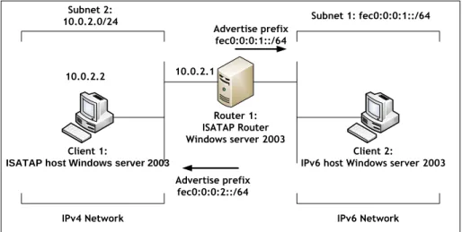
Figure 2-9 below shows the ISATAP experimental design and setup of this research. The network setup involved two computers that function as sender and receiver and these computers were installed with Windows Server 2003 operating system throughout the entire experiment. One computer namely “Client 1” is located in the IPv4 network and configured
as ISATAP client and another computer namely “Client 2” is an IPv6 computer, which is located in the IPv6 network, which also configured as a client. An ISATAP router is used in between the two computers that provide transition between IPv4 network and IPv6 network. The operating system on ISATAP router is varied from Windows Server 2003 to FreeBSD and finally to RedHat Linux accordingly. According to Visoottiviseth & Bureenok (2008), ISATAP router perform three tasks in the transition process“(1) advertising address prefixes to ISATAP hosts, (2) forwarding packets between ISATAP hosts in IPv4-only network and hosts in hosts in IPv6-only network, and (3) acting as IPv6 default router for ISATAP hosts”.
Client 1:
ISATAP host Windows server 2003
Router 1: ISATAP Router Windows server 2003
Client 2:
IPv6 host Windows server 2003 Subnet 2:
10.0.2.0/24 Subnet 1: fec0:0:0:1::/64
IPv4 Network IPv6 Network
Advertise prefix fec0:0:0:1::/64
Advertise prefix fec0:0:0:2::/64
10.0.2.2 10.0.2.1
Figure 2-9: ISATAP test-bed configuration (Visoottiviseth & Bureenok, 2008)
Table 2-4 below shows specification of hardware used in experimental research. All
three hardware contained different processor and memory specifications.
Router Processor: Intel Pentium 4 (1.6GHz) Memory: 512 MB
Sender Processor: Intel Pentium 4 (2.4 GHz) Memory: 128 MB
Receiver Processor: Intel Pentium 4 (2.4 GHz) Memory: 256 MB
To obtain the result of this research, Visoottiviseth and Bureenok used iPerf measurement tool throughout the experiment. The reason that iPerf had been selected was due to the fact that iPerf compatible with Windows and non-Windows operating systems and support both TCP and UDP traffic. Each test ran 10 times with different payload sizes. The performance metrics used in the experiment are throughput, packet loss rate, and maximum number of packets per second at which the router starts to drop packets. There were 15 different buffer sizes used which included 32, 64, 128, 256, 384, 512, 640, 768, 896, 1024, 1152, 1280, 1408, 1420 and 1536 bytes.
2.7.1.1
TCP Performance Result
The result of TCP throughput shows that IPv4 has the highest throughput due to the size of packet header which is smaller than ISATAP header that encapsulate IPv6 header with IPv4 header before the packet is sent through IPv4 network. Among these three protocols, ISATAP has the highest overhead, which places it at the lowest performance. The comparison of throughput on all three operating systems showed that RedHat 9.0 had the highest throughput and Windows Server 2003 has the lowest throughput when the buffer size reaches 896 bytes. However, with throughput below 896 bytes Windows Server 2003 gained the highest throughput performance.
2.7.1.2
UDP Performance Result
In UDP performance measurement, the payload size was changed from 32 bytes to 64, 128, 256, 512, 1024, and 1432 bytes. The result of UDP throughput shows that native IPv4 has the highest throughput followed by native IPv6 and ISATAP has the lowest throughput. The performance ISATAP on the three operating systems showed that RedHat 9.0 has the highest throughput followed by FreeBSD 5.3 and Windows Server 2003 has the lowest throughput. In term of packet loss results, FreeBSD 5.3 and RedHat 9.0 begin to lose packets when the payload size increases to 20000 pps and Windows Server 2003 began to lose packets at 35000 pps.Overall, the packet loss rate of Windows Server 2003 is larger than RedHat 9.0 and FreeBSD 5.3.
2.7.1.3
Discussion
The group of researchers recommended that RedHat 9.0 is the ideal operating system for the implementation of ISATAP because it shows that it produces the highest performance compared to FreeBSD 5.3 and Windows Server 2003. There is no recommendation for any future study in this paper but further study of the same ISATAP protocol can be conducted on the newer version of Microsoft Windows operating systems and Linux operating systems because the newer operating systems usually provide enhancement in performance and bug fixes as applicable.
2.7.2
Study 2
Evaluating BDMS and DSTM transition mechanisms
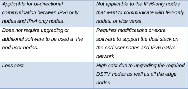
AlJa’afreh, Mellor, and Awan (2008) conducted research on Bi Directional Mapping System (BDMS) and Dual Stack Transition Mechanism (DSTM).The purpose of this research was to identify the differences and evaluate the performance of BDMS and DSTM by implementing these mechanisms on OMNet++ simulation software. BDMS is the mechanism that performs conversion whereas DSTM is the mechanism that performs transition between IPv4 and IPv6.AlJa’afreh et al. (2008) presented Table 2-5 below, which is shown the main differences between BDMS and DSTM.
BDMS DSTM
Uses two types of global addresses that are assigned by the DNS Server for each communication session.
Each communication session is required to have the global IPv4 that assign by a pool of IPv4 addresses. Two IP addresses (IPv4 and IPv6
addresses) are assumed to be globally unique.
Only IPv4 addresses are assumed to be globally unique.
Tunnelling is not required Tunnelling is required
Only translation from IPv4 to IPv6 and vice versa is needed.
Encapsulation and de-capsulation IP packet
Applicable for bi-directional
communication between IPv6 only nodes and IPv4 only nodes.
Not applicable to the IPv6-only nodes that want to communicate with IP4-only nodes, or vice versa
Does not require upgrading or additional software to be used at the end user nodes.
Requires modifications or extra software to support the dual stack on the end user nodes and IPv6 native network
Less cost High cost due to upgrading the required
DSTM nodes as well as all the edge nodes.
Table 2-5: The differences between BDMS and DSTM
2.7.2.1
Performance Result
The performance metrics that the researchers used in their study are round trip time (RTT), End-to-End Delay (EED), and Throughput. According to RTT result shows that BDMS performs better than DSTM with the packet sizes of less than 400 bytes. The reason is due to high overhead that caused by the encapsulation process in DSTM.
The result of End-to-End Delay shows that BDMS gained better performance than DSTM due to high overhead that caused by the encapsulation process in DSTM. The throughput result of both mechanisms shows that BDMS performs better than DSTM with the packet size of less than or equal to 256 bytes but when the packet size is getting larger, the performance of both mechanisms is very much similar.
2.7.2.2
Discussion
Overall both BDMS and DSTM have similar performance with large packet size but BDMS performs better with small packet size (less than or equal to 256 bytes). This is because DSTM has higher overheads than BDMS due to the encapsulation process in DSTM. According to Alja’afreh et al. (2008), BDMS is better than DSTM in terms of cost, applicability, and modification on end user nodes and other nodes on the network. There is no recommendation for any future study in this paper but further study of BDMS and DSTM can be conducted on the different operating systems and physical hardware that could provide results that are more realistic.
2.7.3
Study 3
Performance Investigation of IPv4/IPv6 transition mechanisms
Chen, Chang, and Lin conducted the performance evaluation of different tunnelling transition mechanisms on Windows Server 2003 operating system for their research. Data gathering focused on four parameters such as latency, throughput, CPU utilization, and packet loss rate for both TCP and UDP transmissions. The test was conducted using three tunnelling mechanisms that included Configured Tunnel, 6to4, and Tunnel broker. Three different test-beds were setup for these three tunnelling mechanisms. Chen et al. (2004) presented Table 2-6 below, which shows the comparisons between three tunnelling mechanisms:
Tunnelling Mechanisms
Advantages Limitations Requirements
Configured Tunnel
Stable and secure links for regular communication
Management overhead
No independently managed NAT
ISP registered IPv6 address; Dual Stack routers
6to4 tunnel Connection of multiple
remote IPv6 domains
Number of tunnels supported by the 6to4 router IPv6 prefix (2002::/16); Dual Stack router Tunnel broker Standalone isolated IPv6 end system
Potential security implications
It must know how to create and set a script
Table 2-6: Comparisons of tunnel-based mechanisms
Table 2-6 above shows that 6to4 is an ideal transition mechanism for the implementation during the period of migrating from IPv4 to IPv6.
2.7.3.1
Configured TunnelTest-bed
According to Chen et al. (2004), in Configured Tunnel test-bed, Dual Stack gateway is configured as a tunnel endpoint on one end and Dual Stack router is configured as another tunnel end-point at the other end. The tunnel is established across IPv4 network infrastructure and the encapsulation and de-capsulation will be performed at Dual Stack gateway and Dual Stack router. Configured Tunnel requires manual configuration, which accomplished by using command line interface (CLI).Figure 2-10 below shows the design of the network setup for Configured Tunnel test-bed:
Dual Stack
Gateway
Dual Stack Router
IPv6 server IPv6 server
IPv6 network IPv4 network
Configured Tunnel
LAN (Global) IPv6 network
Figure 2-10: Configured Tunneltest-bed(Chen et al., 2004)
According to Figure 2-7 above, the connection between the two tunnel end points is IPv4 network infrastructure or the IPv4 Internet. In between IPv6 server and Dual Stack Gateway or Routers is IPv6 network infrastructure. The IPv6 packets sent from one IPv6 server to another IPv6 server will be encapsulated with IPv4 header and de-capsulated the header by the Dual Stack Gateway or Router
.
2.7.3.2
6to4 Tunnel Test-bed
In 6to4 tunnel test-bed, 6to4 gateway was configured on one router and the other router is configured as 6to4 relay router. These two routers are functioning as tunnel endpoint that establishes a tunnel across IPv4 network infrastructure say the Internet. The IPv6 packet that is sent from IPv6 node will be encapsulated in IPv4 packet by 6to4 gateway and forwarded to 6to4 relay router through 6to4 tunnel that is established across the IPv4
network. When the packet arrives at 6to4 relay router, the packet will be de-capsulated by 6to4 relay router and forwarded to the global IPv6 network(Chen et al., 2004). Figure 2-11 below shows the network design and setup by Chen et al. (2004) for 6to4 test-bed:
6to4 tunnel IPv4 Network 6to4 relay router 6to4 Gateway Global IPv6 network Private 6to4 IPv6 network
IPv6 Node IPv6 Server
Figure 2-11: 6to4 Tunnel test-bed
2.7.3.3
Tunnel Broker Test-bed
To be able to connect to the tunnel broker Server, tunnel broker client required to have a dual stack configured. In order to establish tunnel between Tunnel Broker client and IPv6 network, Tunnel Broker client must connect to Tunnel Broker Server by using DNS service in Tunnel Broker Server. Figure 2-12 below show Tunnel Broker test-bed.
IPv6 DNS
IPv6 in IPv4 Tunnel 1. Web request on IPv4
2. Tunnel information response on IPv4 Tunnel Broker
3. Tunnel broker configured the tunnel server or router
4. Client establishes the tunnel with tunnel server or router
IPv4 Network IPv6 Network Tunnel Broker Client Tunnel Broker
Figure 2-12: Tunnel Broker test-bed(Chen et al., 2004)
2.7.3.4
Latency Analysis
iteration cycles. The result of latency shows that 6to4 has the lowest latency and Tunnel Broker has the highest latency, which implies that 6to4 performs better than Tunnel Broker transition mechanism.
2.7.3.5
Throughput Analysis
According to Chen et al. (2008) “The packet size used were ranged from 128 to 1024 bytes. The tests were limited to datagram of 1440 bytes to prevent a potential undocumented fragmentation problem in the IPv6 protocol stack”. The formula used by Chen et al. (2008) to calculate throughput is Throughput = Data packet size / Latency. The summary of Throughput analysis shows that 6to4 transition mechanism achieved better performance than Tunnel Broker transition mechanism.
2.7.3.6
CPU Utilization
The CPU utilization was captured on the edge router that functions as sender. CPU utilization was captured by using the built-in Windows Server 2003 task manager tool. The results show that 6to4 transition mechanism consumed higher CPU processing power due to the process of sent and received packets, which required encapsulation and de-capsulation processes.
2.7.3.7
Loss Rate Analysis
In term of loss rate, the result shows that the loss rates increased when the packet size increases. According to Chen et al. (2008)
When the packet size is 64 bytes, the lost rates of the 6to4 mechanism, configured tunnel, and tunnel broker are 1.0%, 1.5%, and 1.6 % respectively. When the size of the packet is increased to 1024 bytes, these loss rates become 4.2%, 5.8%, and 6.8%”.
This analysis shows that 6to4 mechanism had the lowest loss rate followed by Configured tunnel and tunnel broker respectively.
2.7.3.8
Discussion
There was confusion in term of operating system used in this study. The researchers did not state which operating systems were used for the testing at the beginning of the report except in the CPU utilization section there is a statement saying that “the CPU utilization was captured by using Windows Server 2003 Task Manger’s performance monitoring tool” Chen et al. (2008).
As regards the tools, Perfmon can achieve a more accurate result than Task Manager tool because Perfmon produces clear and accurate result of CPU performance. Figure 2.13 below show the screenshot of Perfmon tool, which clearly state the minimum, maximum, and average of the processor percentage.
Figure 2-13: Perfmon CPU performance monitoring tool
At the conclusion of this study, recommendation of any further study has not been state by the researchers. However, further study of these transition mechanisms can be conducted on various operating systems using different measurement tools. Thereby, further establishing the reliability of these findings.
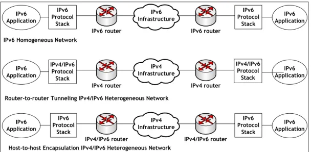
2.7.4
Study 4
Evaluation IPv4 to IPv6 transition mechanisms
Raicu & Zeadally conducted a research study on the performance evaluation of 6over4 and IPv6 in IPv4 tunnelling on windows 2000 platform. The parameters used in this study are throughput, latency, CPU utilization, and TCP connection time. Test-beds were implemented using Ericsson AXI462 and IBM 2216 Nways Multiaccess connector Model 400 routers to connect to a workstation on each separate network.
The following was the specification for both workstations:
Processor: Intel Pentium III 500MHz Memory: 256 MB
HDD: 30GB NIC: 10/100
Windows 2000 professional was installed on both workstations and these workstations were configured to support IPv6 protocol stack in order to operate in dual stack mode with IPv4 standard protocol stack. The performance measurement tool was not mentioned but Raicu and Zeadally(2003) state that the software tools were written in C++ programming. The performance measurement was conducted in three different tests. Figure 2-14below shows three different network setup:
IPv6 Application IPv6 router IPv6 Protocol Stack IPv6 Application IPv6 Protocol Stack IPv6 router IPv6 Infrastructure IPv6 Application IPv4 router IPv4/IPv6 Protocol Stack IPv6 Application IPv4 router IPv4 Infrastructure IPv6 Application IPv4/IPv6 router IPv6 Protocol Stack IPv6 Application IPv6 Protocol Stack IPv4/IPv6 router IPv4 Infrastructure IPv6 Homogeneous Network
Router-to-router Tunneling IPv4/IPv6 Heterogeneous Network
Host-to-host Encapsulation IPv4/IPv6 Heterogeneous Network
IPv4/IPv6 Protocol
Stack