Study of Performance of Security protocols
in Wireless Mesh Network
A thesis report submitted in partial fulfillment of
the requirements for the degree of
Bachelor
Bachelor
Bachelor
Bachelor of Technology in Computer Science
of Technology in Computer Science
of Technology in Computer Science
of Technology in Computer Science
By
Sanjeev Kumar Shukla
Roll No: 10606064
&
Kuna Soren
Roll No: 10606052
Under the guidance of
Mr. Bibhu D. Sahoo
Associate ProfessorII
Department of Computer Science and Engineering
National Institute of Technology Rourkela
Rourkela – 769 008
May 2010
National Institute of Technology Rourkela
Rourkela-769008, Orissa
This is to certify that the work in this Thesis Report entitled “Study of Performance of Security protocols in Wireless Mesh Networks” submitted by Sanjeev Kumar Shukla & Kuna Soren has been carried out under my supervision in partial fulfillment of the requirements for the degree of Bachelor of Technology in Computer Science Engg during session 2006-2010 in the Department of Computer Science and Engineering, National Institute of Technology, Rourkela, and this work has not been submitted elsewhere for a degree.
Place: NIT Rourkela Date : May 8, 2010 (Bibhu D. Sahoo) Associate Professor Department of CSE NIT Rourkela
Certificate
III
No thesis is created entirely by an individual, many people have helped to create this thesis and each of their contribution has been valuable. My deepest gratitude goes to my thesis supervisor, Mr. Bibhu D. Sahoo,
Associate Professor
, Department of CSE, for his guidance, support, motivation and encouragement through out the period this work was carried out. His readiness for consultation at all times, his educative comments, his concern and assistance even with practical things have been invaluable.. We would also like to thank all professors and lecturers, and members of the department of Computer Science and Engineering for their generous help in various ways for the completion of this thesis. A vote of thanks to my fellow students for their friendly co-operation.
(Sanjeev Kumar Shukla) 10606064, (Kuna Soren) 10606052, B.Tech.(Comp. Sc.Engg), 2006-2010.
Acknowledgements
IV
Wireless Mesh Networks (WMNs) represent a good solution to providing wireless Internet connectivity in a sizable geographic area; this new and promising paradigm allows for network deployment at a much lower cost than with classic WiFi networks. Standards-based wireless access takes advantage of the growing popularity of inexpensive Wi-Fi clients, enabling new service opportunities and applications that improve user productivity and responsiveness. The deployment of WMNs, are suffered by : (i) All, the communications being wireless and therefore prone to interference, present severe capacity and delay constraints, (ii) The second reason that slows down the deployment of WMNs is the lack of security guarantees. Wireless mesh networks mostly susceptible to routing protocol threats and route disruption attacks. Most of these threats require packet injection with a specialized knowledge of the routing protocol; the threats to wireless mesh networks and are summarized as (i) External attacks: in which attackers not belonging to the network jam the communication or inject erroneous information, and (ii) Internal attacks: in which attackers are internal, compromised nodes that are difficult to be detected. The MAC layers of WMN are subjected to the attacks like Eavesdropping, Link Layer Jamming Attack, MAC Spoofing Attack, and Replay Attack. The attacks in Network Layer are: Control Plane Attacks, Data Plane Attacks, Rushing attack, Wormhole attack, and Black Hole Attack. In this project work we are concern with the threats related to Network layer of WMN based upon 802.11i and analysis the performance of secure routing protocols and their performance against the intrusion detection.
V
Contents
Section
Description
Page No.
Chapter 1 Introduction
1.1 Introduction 1
1.2 Literature Review 3
1.3 Organization of the thesis 10
1.4 Conclusion 10
Chapter 2 Security Issues in Wireless Mesh Networks
2.1 Introduction 11
2.2 Theoretical Throughput Capacity 11
2.3 Resource Management 22
2.4 Fairness
2.5 Reliability And Robustness 2.6 Security
25
Chapter 3 SECURE POSITION – AIDED AD HOC ROUTING
3.1 SPAAR FEATURES 26
3.2 SPAAR Environment 29
3.3 SPAAR Setup:
3.4 The Neighbor Table
3.4.1 Adding Nodes to the Neighbor Table 3.4.2 Neighbor table Maintenance
3.4.3 Hello message
3.5 Route discover and route Maintains: 3.5.1 Route Request (RREQ)
3.5.2 Route Replies (RREP) 3.5.3 Location Request Messages
VI
3.5.4 Route Error Messages(RERR)
Chapter 4 Faults Detection and Isolation in Wireless Mesh Networks
4.1 Introduction 38
4.2
Simulation Setup
394.3 ALGORITHM FOR SIMULATION 44
4.4
Simulations
494.5 Conclusion 53
References 58
VII
List of Figures
Figure
No Name of the Figure
Page No. 3.2 Adding A node to The neighbor Table 12 3.3 Route Request(RREQ) Propagation 15
VIII
1.1 Introduction
Wireless mesh networks (WMN) are multi-radio, multi-hop networks with the ability of dynamically self organizing and self configuring. They can automatically establish ad hoc networks and maintain mesh connectivity between them. They are envisioned to be compatible and interoperable with existing wire line and wireless networks (conventional wireless, cellular networks, sensor networks) through gateways. WMN’s diversify the abilities of ad hoc networks as they are composed of mesh routers and mesh clients. Mesh clients exhibit pure ad hoc behavior by performing routing and self configuration. The mesh routers are the main addition, on top of providing a mesh of self-configuring and self-healing Links among themselves, they also provide a gateway functionality which enables integration with existing wireless and wire line networks. A mesh router also contains additional routing functions to support mesh networking. A wireless mesh router should be able to achieve the same coverage compared to a conventional wireless router but with lower transmission power. Hence, even though they exhibit ad hoc behavior, they still have a network architecture associated; this can be manipulated when looking towards intrusion detection techniques.
There are primarily three networks Architectures associated with wireless mesh networks [1]. There is the infrastructure or backbone architecture which is solely composed of mesh routers. This is considered as backbone architecture as it provides infrastructure to wired and wireless clients. This allows integration of mesh networks with already existing communication networks. The second architecture considered is the client wireless mesh network architecture which is comprised of mesh clients that provide peer to peer networks among client devices.
The main difference between mesh clients and mesh routers is that clients only have one wireless interface and less computational abilities. Finally the hybrid architecture
Chapter
IX
is composed of the backbone and client meshing architectures. This way, the
infrastructure provides connectivity to other networks [ 3] And the routing abilities of clients provide improved connectivity and coverage within the mesh network.
1.2 Literature Review
For any application (not necessarily on WMNs), the following general goals are desired to ensure security.
Confidentiality or Privacy: The communication between users must be secured such that the information cannot be disclosed to any eavesdroppers.
Integrity: The whole transmission paths must be protected to ensure the messages
are not illegally altered or replayed during the transmission.
Availability: Applications should provide reliable delivery of messages against
denial of service (DoS).
Authentication:When a user sends messages, there should be some processes to identify the user to ensure the messages are really sent by the claimed sender rather than fabricated by someone else.
Authorization: Before any user performs some tasks, there should be mechanism to
ensure the corresponding users have the right to do them.
Accounting: When a user is using some services, some process should be able to
X
Threats and Vulnerabilities in Different layer of WMN
LAYER Attacks
Application Layer Repudition, data corruption
Transport Layer Session hijacking, SYN flooding
Network layer Wormhole, blackhole, Byzantine,
Flooding, resource consumption, location disclosure attack
Data link Layer Traffic analysis, monitoring, disruption MAC(802.11) WEP weakness
Physical Layer Jamming, interceptions, eavesdropping
Multi-layer attacks Dos, impersonation, replay, man-in-the-middle
In our project we are considering the attack in the Network Layer, the threats to this layer is summarized as following:
Routing Protocol Threats
Wireless mesh networks may be susceptible to routing protocol threats and route disruption attacks. Many of these threats require packet injection with a specialized knowledge of the routing protocol however, these threats are unique to wireless mesh networks and are summarized below:
XI
Black-hole. An attacker creates forged packets to impersonate a valid mesh node and subsequently drop packets, where attracting packets involves advertising routes as low-cost.
Grey-hole. An attacker creates forged packets to attack and selectively drops,
routes or inspects network traffic.
Worm-hole. Routing control messages are replayed from one network location to another, which can severely disrupt routing.
Route error injection. An attacker disrupts routing by injected forged route error message to break mesh links. Relative to the other routing attacks, this attack conceivably has high exploitability because it does not require detailed knowledge of the routing protocol state model (e.g., a replay attack is possible, and route errors are typically stateless).
Metro-WiFi Public Access Threats:
Spoofing of wireless infrastructure. An attacker uses an “evil twin” or “man-in-the-middle”attack to execute an information disclosure threat. In an enterprise deployment, such attacks are mitigated using EAP methods that allow mutual authentication between a client and the infrastructure (e.g., EAP-TTLS, EAP-TLS or EAP-PEAP).
Denial-of-service attack. An attacker may either use IP flooding as well as attacking network services, or 802.11 MAC management attacks. The 802.11i-based link level security model supports authentication, key distribution and encryption for mesh management frames, whereMAC management frame protection is not addressed within 802.11s.
Theft-of-service attack. An attacker steals valid user credentials or performs paid-user session hijacking (e.g., “freeloading”). Many Wi-Fi systems use a service gateway or captive portal to secure paid access – a captive portal uses SSL-secured Web page where users authorization credentials. After authentication, the captive portal authorizes the client to network access by registering the valid client MAC and IP addresses in the gateway. Alternatively,
XII
malicious users could relay traffic across the mesh network without traversing a network gateway (e.g., peer-to peer traffic across the mesh backhaul)
1.2.2 Network Topology
In a wireless mesh network all Aps may or may not have direct connection to the network gateways. Hence they need to forward their through the network to reach the gateway. Again we may extend the access to the gateway by forming a mesh topology between the mobile nodes as happens in case of ad-hoc networking. There exists a connection between every pair of nodes in the network realm in a wireless mesh topology. There are two types of mesh topologies as follows:
Full Mesh Topology: Every node is connected to every other node in the network. Full mesh topology yields greatest amount of redundancy, hence difficult to realize in a large scale using mesh routers, but small areas like small campus or offices may be ideal. But if any router fails, then the packet can be routed through other routers. Hence the network is robust and fault-tolerant.
Partial Mesh Topology: Some nodes are arranged in full mesh topology but others are only connected to one or more nodes in the network. This is realizable for small to large scale networks fulfilling the requirements. This can be of following types:
1) Point-to-Point
2) Point-to-Multipoint or Multipoint-to-Point 3) Multipoint-to-Multipoint
4) Metropolitan
Mixed Node Topology: A mixed node topology is the complex form of wireless network which is composed of two radios and two high gain antennas in direct communication with each other and a third party wireless bridge/repeater. Though the links are quick to deploy but not scalable to create a large network. Clients may use these bridge/router nodes in an indoor environment and the main benefit so achieved is low installment cost.
XIII
Topology has a great impact on the performance of any routing protocol been applied. Logical Arrangement of nodes under an AP and arrangement of routers in the network plays big role in packet transmission. The routing algorithms are been broadly classified basing upon following criterion: [4]
Routing Philosophy: Routing approaches can be viewed as proactive, reactive and hybrid type. In proactive ones, paths are established regardless of if there exist any data to transmit. In reactive, path is established on-demand. Hybrid protocols implement both type of path establishment.
Network Organization: Network may follow flat organization where all nodes have same role to play but in hierarchical organization some nodes may have specialized functions. Super nodes may exist for various network management works.
Location Awareness: Routers may or may not have any information about location of various nodes in the network.
Mobility Management: WMN has to manage the mobility of nodes throughout the network. As nodes move about, they change their logical position, the corresponding they attached to. But there exists several issues that need to be taken care of separately
1.3 Organization of the Thesis
The whole thesis is organized into 5 chapters. Chapter 1 introduces Wireless Mesh Network and presents the overview of this thesis work. It also presents the literature review of Security problem. Chapter 2 presents the present security Issues and their impact on the performance. Chapter 3 deals with the introduction of different secure protocols proposed for the security of Wireless Mesh Networks. Chapter 4 presents the results obtained by comparing the two secure protocols in terms of some metrics. Chapter 5 deals with Fault detection and Isolation in Wireless mesh networks. At last, the report comprises of future enhancements and conclusion to this thesis work followed by references used for this work.
XIV
1.4 Conclusion
In this chapter, introduction and overview of
this thesis work is presented. The background for
this thesis work is given. There exist different
types of attacks which can be performed on the
Wireless Mesh Networks
.
Wireless mesh networks
mostly susceptible to routing protocol threats and
route disruption attacks. Most of these threats
require
packet
injection
with
a
specialized
knowledge of the routing protocol. In this project
work we are concern with the threats related to
Network layer of WMN based upon 802.11i and
analysis
the
performance
of
secure
routing
protocols
and
their
performance
against
the
XV
Chapter
2
Issues in Wireless mesh
Networks
2.1 Introduction
In this chapter we discuss important aspects that must be taken into account in wireless mesh networks, such as the throughput capacity, fairness, reliability and robustness, and resource management.Security is a major issue in both wired and wireless networks. In a wired network, the transmission medium can be physically secured, and access to the network as well. On the other hand, in a wireless network, security is more difficult to implement, since the transmission medium is open to anyone within the geographical range of a transmitter. In recent years, many security schemes have been proposed for Ad hoc wireless networks that can also be applicable to WMNs. However, these schemes are not good enough to be implemented in real scenarios. Moreover, because the difference in infrastructure between Ad hoc and WMN, some proposed solutions for the first are ineffective for the later.[1][16] In order to better understand the security issue, we need to learn what attacks exist.
2.2 Theoretical Throughput Capacity.
In data communication systems, throughput is defined as the number of bits, or characters (data) per unit of time that is delivered over a wired or wireless medium [13]. As an example, we could say that throughput is the amount of data per second passing through a wire connecting two computers. Then, the total network capacity is the maximum throughput of a node or communication link. [14]defines the throughput capacity as the maximum feasible throughput π with high probability (asymptotically approaching to 1), where π is the arrival rate in bits per second, and every node in the network sends data with a high probability to its chosen destination. Thus, the throughput
XVI
theoretical upper limit of every node throughput capacity is asymptotically limited by π (1/√n) where n is the number of nodes in the network. Therefore, increasing the number of nodes, the throughput capacity per node becomes unacceptably low. In general, the throughput capacity achievable in a WMN is proportional to the π (W × n−1/d) where d is the dimension of the network and W is the total bandwidth. One approach to improve the throughput capacity is the use of multiple radio and fine tuned protocols.WMN nodes have a more limited throughput capacity in a single-channel system than in a multi-channel system. Moreover, other factors contribute to the throughput degradation such as characteristics of MAC protocol, the hidden terminal problem, the exposed node problem, and the error rate in the wireless channel; which have more effect in a single-channel system.
2.2 Resource Management
Resource management means the efficient management of network resources such as energy, bandwidth, interfaces, and storage. For example, if we consider a node with two interfaces, one low-power node and another regular one, then the WMN can use efficiently the energy resources. The overall power consumption, even in idle mode, depends very much on the type of interface. Therefore, in an IEEE 802.11-based WMN with limited energy reserve, an additional low-power and low data rate interface can be used to carry out-of-band signaling information to control the high-power and high-data rate data interface. Bandwidth resources can also be managed better in a multi-radio environment. For example, the load balancing across multiple interfaces could avoid a channel to get very congested and therefore a possible bottleneck. In addition, the bandwidth of each interface could be aggregated to obtain a high effective data rate. Finally, in such a bandwidth aggregation mechanism (bandwidth striping), dynamic packet scheduling can be utilized to obtain an even better performance.
XVII
Fairness, from the MAC perspective, can be achieved if the MAC protocol does not present preference for any single node when multiple nodes are trying to access the same channel. Then, we can say that the bandwidth is shared fairly[15]. WMN single-radio nodes also face high throughput unfairness. We say that a network has high throughput fairness if all nodes get equal throughput under similar conditions of source traffic and network load. WMNs show high throughput unfairness among the contending traffic flows especially when CSMA/CA-based MAC protocols are employed for contention resolution. Three important properties associated with CSMA/CA-based MAC protocols, when used in a WMN environment are: (i) information asymmetry, (ii) location dependent contention, and (iii) half-duplex character of single-channel systems. Information asymmetry is caused by the lack of information at certain nodes, but also having excessive information may also contribute to throughput unfairness. For example, when a node is exposed to two flows, its Network Allocation Vector (NAV) is always set and therefore abstains from transmitting. In addition, the half-duplex property of a interface system is another property that causes high throughput unfairness in a single-radio WMN. Due to the half-duplex characteristics, no node can simultaneously receive and transmit over the network.
2.4Reliability And Robustness
WMNs improve the reliability and robustness of communication. The partial mesh topology in a WMN provides high reliability and path diversity against node and link failures. Multi-Radio WMNs (MR-WMN) provide the most important advantage for robustness in communication diversity. For example, in wireless systems channel errors can be very high compared to wired networks; therefore, graceful degradation of communication quality during high channel errors is necessary. The use of multiple radio interfaces allows frequency diversity; therefore instead of having a full loss of connectivity, we achieve graceful degradation. Moreover, MRWMNs can use appropriate radio switching modules to achieve fault tolerance in communication either by switching the radios, channels, or by using multiple radios simultaneously.
XVIII 2.5 Security
Security is a major issue in both wired and wireless networks. In a wired network, the transmission medium can be physically secured, and access to the network as well. On the other hand, in a wireless network, security is more difficult to implement, since the transmission medium is open to anyone within the geographical range of a transmitter. In recent years, many security schemes have been proposed for Ad hoc wireless networks that can also be applicable to WMNs. However, these schemes are not good enough to be implemented in real scenarios. Moreover, because the difference in infrastructure between Ad hoc and WMN, some proposed solutions for the first are ineffective for the later.[1][16] In order to better understand the security issue, we need to learn what attacks exist. Attacks can be seen from a general perspective as active and passive attacks [2], and from the network layer, specifically with respect to routing protocols [17]. In active attacks, information is injected into the network by replicating, modifying or deleting exchanged data. On the other hand, in passive attacks, one subtype is passive eavesdropping, where the attacker intents to discover nodes information by listening to ongoing traffic.
From the routing perspective, [17] identifies several specific attacks targeting the operation of a routing protocol.
1. Location Disclosure: It happens when the attacker tries to obtain network information such as the location of a node, or the network structure.
2. Black Hole: In this attack, false routing advertising is injected in such a way that the attacker is able to capture most packets from other nodes with the purpose of eavesdropping, or perform denial of service by dropping all received packets.
3. Replay: In replay attack, previously captured routing traffic is sent back into the network to target new routes.
XIX
4. Wormhole: This attack requires two malicious nodes where one node captures routing traffic, and sends it to the other malicious node. Then, the second node can send back selective information to the network.
5. Blackmail: Here, the attacker can fabricate a list to block nodes and inject it into the network. This attack targets routing protocols that block malicious nodes by sending a black list of offenders to legitimate nodes.
6. Denial of Service: This attack has two types: a) Routing table overflow, and b) Sleep deprivation torture. In the first type, the attacker floods the network with bogus route creation packets in order to prevent the correct creation of routing information, and to consume resources of nodes. In Sleep deprivation torture, the attacker sends diverse routing information to a specific node in order to make it consume its batteries because of the constant routing processing.
7. Routing Table Poisoning: In this attack, the routing table is affected by receiving modified messages the routing tables of participating nodes. Thus, routes may not be optimal, or routing loops, and bottlenecks are produced. Since most important attacks are identified, the research community is constantly addressing the security issue by proposing new routing protocols using three different means or the a combination of them: 1) symmetric cryptography, 2) asymmetric cryptography, and 3) reputation systems. Proposed routing protocols include the following[18]:
• Authenticated Routing for Ad hoc Networks (ARAN)
• ARIADNE: A Secure On-Demand Routing Protocol for Ad Hoc Networks. • Detecting and Correcting Malicious Data (DCMD)
• Secure Ad hoc on demand Distance Vector (SAODV)
• Secure Efficient Distance Vector Routing for Mobile Wireless Ad Hoc Networks (SEAD)
• Secure Link State routing Protocol (SLSP) • Secure Position Aided Ad hoc Routing (SPAAR) • WATCHDOG-PATHRATER
• Ad hoc on demand Distance Vector (AODV-SEC)
• Building secure routing out of an Incomplete Set of Secure associations (BISS) • PACKET-LEASHES
XX
• Vehicle Ad hoc network Reputation System (VARS) • Endair ALoc [16]
Other approaches at the link layer implement mechanisms based on cryptography to address authorization and privacy on radio links. In addition, the IEEE 802.11 standard considers Wired Equivalent Privacy (WEP) to provide security in wireless networks. WEP supports data encryption and integrity by using a secret key shared by all devices of a WLAN, or a pair-wise secret key shared by only two communicating devices.
2.4 Conclusion
In this chapter we discuss about the important issues in Wireless Mesh Network and their impact on the performance of the Networks we are also considering various secure protocols designed for wireless mesh network.
XXI
Chapter
3.
SECURE POSITION – AIDED AD HOC ROUTING
In this chapter we introduce SPAAR. We will begin by discussing some important features of SPAAR and describing the high risk environment that is designed for. We introduce seven security requirements for secure routing in such a high risk environment. Next we describe the SPAAR neighbor table maintenance protocols. We conclude this chapter with a description of the route discovery protocols and route table maintained protocols.
3.1 SPAAR FEATURES
SPAAR uses position information to improve performance and security , while keeping position information protected from unauthorized nodes . for MANET routing protocols to achieve a high level of security it is imperative that a node only accept routing message from verified one hop-neighbors. In SPAAR a node can verify its one hop-neighbor before including them in the routing protocol. This is made possible by the use of geographical location conformation. SPAAR requires that each device have some means of determine its own location. GPS receives have become relatively inexpensive and lightweight. Therefore, we feel it is reasonable to assume that all devices in our network could be equipped with a GPS receiver. In addition, recent advance in GPS security make it more practical for use in a high risk environment [17]. In the case that a node is unable to determine its location either due to lack of a GPS receiver or terrain obstacle a node may use a location proxy as describe in [6].
In SPAAR, the source node must also know the geography location (or a approximation) of the destination. This may be calculated from the most recent location and most recent velocity information stored in the source node’s route table. However, if this is the source nodes first attempt at communication with a particular destination the source has no way of calculating the destinations position. in this situation a selective flooding algorithm is used to reach the destination and receive its position information. While a location service [18,5] is not assumed the use of such a service would significantly reduce the overhead involved in SPAAR.
XXII
SPAAR makes use of a trusted certificate server. An alternate implementation of SPAAR that’s takes advantages of the opportunity for the exchange of security parameters prior to node deployment may be possible under certain conditions. This implementation would not require a trusted certificate server. In the target environment, a tactical plan of some sort usually exists. In many cases it is possible to definite the set of nodes that a particular node will communicate with as a one hop neighbor. Depending on the size of this set, a node could store these nodes public key in non voltaic memory. Although this solution does not scale, it may be applicable in the target environment, and when applied it eliminate the need for a trusted certificate server in our protocol.
With SPAAR, one could use any one of the different geographic forwarding techniques to make forwarding decision, with little modification to the SPAAR protocol. For simplicity’s sake we choose to use LAR scheme 2 with d=0[5].
3.2 SPAAR Environment:
Due to the numerous applications of ad hoc networks, different ad hoc routing protocols must be designed for and tailored to specify environments. SPAAR was designed for use in a high risk tactical MANET.
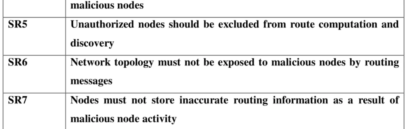
A routing protocol may be considered secure if it meets the security requirements for its environment of use. In [12] the authors classify ad hoc networks into three environments open, managed-open and open-hostile. Each environment differs greatly in its security needs and the opportunity for pre-deployment coordination. The authors describe secure routing protocol design for the managed open environment, where security is a concern, through not the primary concern. SPAAR targets an environment similar to the managed hostile environment by satisfying the set of security environment listed in Table 3.1 which is an adoption of the security requirements of the managed – hostile environment describe in [12].
SR1 Fabricated routing message cannot be injected into network by malicious nodes
SR2 Routing message can not be altered in transit by malicious nodes SR3 Routing loops cannot be formed by malicious nodes
XXIII malicious nodes
SR5 Unauthorized nodes should be excluded from route computation and discovery
SR6 Network topology must not be exposed to malicious nodes by routing messages
SR7 Nodes must not store inaccurate routing information as a result of malicious node activity
Table 3.1 Security Requirements
The managed hostile environment is described as a MANET formed by military nodes in a betel environment and emergency response crew in a disaster area. In this type of environment, security is essential and the protection of node location is often necessary. Nodes are generally deployed exchange of security parameters often exists. Sensitive information is passed between nodes, and malicious nodes are a constant threat.
It is important to distinguish malicious nodes from compromised nodes. SPAAR is designed to define against malicious nodes. For the purpose of this paper, we define a malicious node to be an unauthorized node attempting to disrupt or attack the network. Adversaries deployed malicious nodes to engage in a malicious activity such as eavesdropping, message replay, message distortion and impersonation. SPAAR makes use of encryption to thwart such attack.
We define a compromised node to be a authorized node deployed by a known source but it has been overtaken by the adversary. Compromised nodes can produce valid signatures and posses valid certificate. A compromised node may or may not engage in malicious activity or misbehave.
As a result detection of compromised nodes can be very difficult. in many cases it is difficult to distinguish malicious activity by a compromised node while minimizing the potential for damage from attacks by compromised node.
While a SPAAR protected network will not be safe from all malicious attacks by compromised node , intrusion detection system(IDS) can help a identify compromised nodes and mitigate routing misbehavior. In[19] Zhang and lee introduces an intrusion detection system for ad hoc network. In their approach every nodes participates in
XXIV
intrusion detection and response. Each node is responsible for detecting sign of intrusion locally and in dependently. Neighboring nodes can collaborate to investigate in a broader range if necessary. Individual agents run independently on every node monitoring local activity, collectively forming an IDS to defend wireless ad hoc networks.
Methods of detecting and mitigating routing misbehavior in MANET’s are discussed in [20]. The authors present two routing protocol extensions to mitigate routing misbehavior: the watchdog and the pathrater. The watchdog identified misbehaving nodes while the pathrater uses this knowledge of misbehaving nodes to choose the network path most likely to deliver the packets. Watchdog and pathrater increase overall routing overhead, however this is offset by the increase in network throughput in the presence of misbehaving nodes.
3.3 SPAAR Setup:
SPAAR does not require a preexisting online key management system in the MANET. Knowledge of the public key of other networks nodes or a service that provides the public key of all nodes on the network is not required. SPAAR does require that each node have access to a trusted certificate server before it can participate in the routing protocol. Because the targeted environment generally affords some amount of node preparation prior to deployment we assume that nodes have access to such a certificated server before entering the MANET. to participate in SPAAR, each node requires a public/private key pair, a certificate binding its identity to its public key, and the public key of the trusted certificate server.
All nodes are deployed with the private part of a public/private key pair. Prior to deployment, each node will request a certificate from a trusted certificate server T. the certificate bind a node’s identity with its public key and is signed by T. The certificate is time stamped and has an expiration time. Each node will process T’s public key so it can decrypt certificates of other node. This allow a node N1 to inform another node N2 of its public key, assuming node N2 was deployed correctly with T’s public key to decrypt certificate.
Certificate = [identity, public key, time, expiration]
XXV
With SPAAR, each node maintain a neighbor table that contains the identity and position information of each verified neighbor, along with the cryptography key required for secure communication with each neighbor(Table 3.2). A node only accepts routing messages from a node in its neighbor table.
Table 3.2 Neighbor table ID Neighbor’s identification
PK Neighbor’s public key verified from its certificate GDK Neighbor’s group description key
MLR Neighbor’s most recent location
LUSN Neighbor’s location update sequence number TR Neighbor’s transmission range
3.4.1 Adding Nodes to the Neighbor Table
Adding nodes to the neighbor table is a three step process that is illustrated in figure 3.2. in step 1, a node N broad cast a HELLO message with its certificate CERT_N. any nodes within range of N, wishing to be recognized as a neighbor, decrypt N’s certificate to verify N’s public key and create an entry for N in the neighbor table where N’s public key will be stored.
In Step 2, nodes respond to N with a hello reply (HELLO_REP) that includes their certificates, MLR and TR signed with their public key and encrypted under N’s public key. Upon receiving a HELLO_REP from a neighbor node X1. N will verify that X1 truly a one hop neighbor with the method in figure 3.1.
If N has verified a node as a one hop neighbor, in step three N will store the node’s public key, most recent location and transmission range in N’s neighbor table. If this is the first neighbor to the added to the neighbor table, N will generate a public/private key pair, which we call a neighbor group key pair. The private part of N’s neighbor key pair will be called N’s group encryption key and denoted GEK_N. The public part of node N’s neighbor group key pair will be called N’s group decryption key, denoted GDK_N. N distributes GDK_N to each of this neighbors once they have been verified as one-hop neighbor. The GDK is signed with N’s private key to provide
XXVI
authentication and encrypted under the neighbor’s public key for privacy. Upon receiving the GDK_N. N’s neighbor store it in their neighbor table.
At this point X has the capability to accepts routing packets from N. However, X will not do so until it has verified N as a neighbor. This will occur after X broadcasts a HELLO message and the above steps are executed. This table state will last, at most, the time between HELLO message broadcast of X.
3.4.2 Neighbor table Maintenance
Each node periodically broadcast a table update message to inform the neighbor of its new MLR. TR and LUSN. Table update message are encrypted with a nodes group encryption key. Neighbors of N decrypted the table update message, analyze the new position information to verify that the neighbor is still a one-hop neighbor, and update their neighbor table with the new position information.
Step 1
[HELLO, CERT_N]
Step 2
[hello_rep, Cert_X,[MRL, TR, LUSN]X_k]N_k
Step 3 [[GDK_N]N_k]X_k
Figure 3.2 adding A node to The neighbor Table
The location update sequence number, LUSN, is a time stamped sequence number that is incremented each time N broad casts a table update message or construct a RREP containing its position information . Representing the freshness of location information, the LUSN prevents reply attack of table update message. A node use the LUSN in the RREQ to inform its neighbor of the freshness of the coordinates it possess for the destination.
When a table update message is received, the LUSN is time stamped allowing the node to determine how much time has passed since it has received a table update from its neighbor. It should be noted that the LUSN time stamp is not the exact time of the MRL coordinates for the destination. The MLR coordinate are from time t = (LUSN time
N
N
X
N
X
XXVII
stamp-propagation delay of the message that included the LUSN). After a time period has elapsed without a table update from a neighbor, the link to the neighbor is assumed to be broken and the neighbor is deleted from the neighbor table.
The interval at which a node broadcasts a table update depends on its rate of mobility. A node with a high mobility rate will broadcast table update messages more frequently in an effort to keep its neighbor up-to-date. To offset the overhead involved with such a proactive approach, table update messages are piggybacked on all routing message encrypted with a node’s neighbor group key (RREQ and location request message).
3.4.3 Hello message
All nodes broadcast periodic HELLO messages allowing for new neighbors to be added to the neighbor table. The HELLO message contains the sender’s public key certificate. A node receiving a HELLO message from N checks to see if the GDK field has a value. If the node has a value for node’s N’s GDK field, it is already in N’s neighbor table, or it has no value for the nodes GDK field in the neighbor table. It will send a HELLO_REP message as previously described. As with table update message, the interval between HELLO messages is dependent upon node mobility.
3.5 Route discover and route Maintains:
In SPAAR, a source node initiates the route discovery process by broadcasting a RREQ, upon receiving the RREQ the destination node responds with a RREP. The route discovery process is described in detail in the following section.
3.5.1 Route Request (RREQ)
A node N begins the route discovery process by calculating an estimation of the destination’s current position (velocity x age of position coordinates). Next, N broadcast a RREQ contains the RREQ_SN(see table 3.2), the destination’s identifier, N’s distance to D, the destination’s LUSN, all encrypted with its group encryption key(see figure 3.3). The RREQ_SN is incremented each time a node transmitted a RREQ’s. It is used to prevent replay attacks of RREP and RERR messages.
N->BC:[RREQ_SN,D,DIST_ND,MRL_D,LUSN] GEK_N
s
XXVIII
N->BC:[RREQ_SN,D,DIST_ID,MRL_D,LUSN] GEK_I
Figure 3.3 Route Request(RREQ) Propagation
Recipients of the RREQ, that are neighbor of N, decrypt it with N’s group decryption key. A succefull decryption of a RREQ implies that the sender of the RREQ is a one hop neighbor. As LAR scheme 2 specifies, an intermediate node cheeks to if it is closer to destination D. If an intermediate node has the destinations coordinates with a more recent LUSN, it uses those coordinates for the comparison instead of the coordinates contained in the RREQ.
If the intermediate node is not closer to the destination, the RREQ is dropped. If either is closer, the node re-broadcasts the RREQ with its identifier and distance to S, encrypted with its group encryption key. If the intermediate node has the destination’s coordinates with a more recent LUSN, those coordinates replace the older coordinates in the RREQ. Intermediate nodes record, in their route table(Table 3.3), the address of the neighbor from which they received the RREQ, thereby establishing a reverse path. This process is repeated until the destination is reached.
Table 3.2 Route Table
RREQ_SN Route request sequence number used to identify a RREQ S/DID The source and destination I\D’s
REVERSE The next hop in the reverse path to the source FORWARD The next hop in the forward path to the destination MRL Destination’s most recent location
TR Destination’s transmission range
LUSN Destination’s location update sequence number VEl Destination’s velocity
A/I The active/inactive flag
Each node maintains a route table containing the fields shown in table 3.3. An entry in the route table is created when a RREQ is received or a node initiates a route discovery. The RREQ_SN from the route request is stored to prevent RRER reply attacks. The source and destination addresses associated with route request are also
I
XXIX
stored. The reverse field is the address of the node from which the RREQ was received and the forward field is the address of the node from which the corresponding RREP was received. The location information for the destination is stored in the MRL, TR and LUSN fields. Each route in the route table is initially marked active, however a route may be deactivated for a number of reasons discussed in section 3.5.5.
3.5.2 Route Replies (RREP)
Upon receiving a RREQ, the destination constructs a RREP containing the RREQ_SN, its MRL, its velocity, and a LUSN. The destination’s certificate is also included enabling any node to verify the destinations signature on the contents of the RREP. The destination signs the RREP with its private key and encrypts with its public key of the neighbor from which it received the RREQ. The RREP propagates along the reverse path of the RREQ, being verified at each hop(figure 3.4)
D->I:[CERT_D,[RREQ_SN,MRL_D,VEL_D,LUSN]D_k]I_k
D->N:[[CERT_D,[RREQ_SN,MRL_D,VEL_D,LUSN]D_k]I_k]N_k
Figure 3.4 Route Reply
Intermediate nodes upon receiving a RREP decrypt it with their private key and verify the signature with the public key of the neighbor node they receive it from .Next, the contents of the RREQ are decrypted with the public key of the destination. If the decryption is successful, a forward entry is then added to the intermediate nodes route table that points to the nodes from which the RREP was received. An un successful decryption implies that the contents of the RREP have been tempered with, and the RREP is discarded .Intermediate nodes sign the RREP and encrypts it with the public key
D
I
N
XXX
of the next node in the reverse path. The RREP is then forwarded to the next node in the reverse path.
An intermediate node may receive many RREPs in response to one RREQ. The first RREP received is the one that will be used; however intermediate nodes create entries in their routing tables for the first three RREPs they receive from different nodes for a given RREQ.
Following the successful receipt and authentication of a RREP, the source node verifies that the RREQ_SN matches the RREQ_SN from the initial RREQ. This is done to prevent reply of RREPs by malicious nodes. The source node then creates a new entry in the route table. The source node time stamps the LUSN so it can determine how much time is passed since the last update. As with intermediate nodes, the source node will use the route from the first RREP it receives from different nodes for a given RREQ. In a case that a source node does not receive RREP in response to a RREQ flooding must be used.
3.5.3 Location Request Messages
There will be cases when nodes has no previous location in formation for a destination to include the RREQ .In this case a node broadcasts a location request message to its neighbors in an attempt to discover the location of the destination.
N--- BC:[LOC_REQ,D]GEK_N
Any neighbor that possess the location coordinates for the destination will respond to S with a signed location reply ,encrypted with N’s public key.
NeighborN;[[LOC_REP,D,MRLD,VELOCITY_D,LUS N,AGE ]Neighbor_k]
It does not assume clock synchronization between nodes ,thus the local timestamp on a LUSN is I irrelevant to another node. If neither N nor any N’s neighbor have the location coordinates for destination D,N must revert to a selecting flooding algorithm. N broadcast a RREQ with the distance to the destination set to infinity, it will check to see if it has coordinates for the destination and the destination coordinates. If it does not ,it will rebroadcast the RREQ with the distance to the destination set to infinity. This process is repeated until the destination is reached.
XXXI 3.5.4 Route Error Messages (RERR)
Nodes mark routes as either active or inactive in the route table .A route may be deactivated for a number of different reasons. If a stored route remains unused after a certain timeout periods, the route is deactivated. If data is received for a de-activated route, a route error massage is constructed and propagated upstream towards the source, in the same function as a RREP .A RERR consists of the massage type identifier and a route request sequence no. The RRSQ_SN is included in the RERR messages to identify the route that should be deactivated. When a node receives a RERR message, it deactivates the route associated with the Specified RREQ_SN.
I2I1 : [[RERR.RREQ_SN]I2_K-]I 1_K]
The RERR is signed with the sending nodes private key and encrypted with the appropriate neighbor‘s public key. When a node receives and successfully decrypts a RERR it will update its routing table by marking the route associated with the RREQ_SN as inactive. If the node is not the source of the path to be deactivated it signs encrypt and transmit the RERR to the appropriate neighbor. When the source receives the RERR, it will deactivates the route and try an alternate if one is stored in its route table .If there isn’t an alternate route or the alternates routers fail, the source re-initiates the route discovery process for the destination.
XXXII
Chapter
4
Simulation Setup and Results
4.1 Introduction
The security issue related to wireless mesh network can be solved by implementing SPAAR as described in the previous chapter. The simulations have shown the effect of the different attacks on the performance of WMN.
The performance metrics studied are:
1. Expected Transmission Count (ETX): It accounts for data loss due to medium access contention and environmental hazards, and considers the number of retransmissions needed to successfully transmit a packet over a link.
2. Hop Count: Hop count is the most commonly used metric in wireless multi-hop networks. The path selected is the one minimizing the number of links between a given source and destination node.
4.2 Simulation Setup
The simulation considers a setup with a three stored building serviced by nine routers, three on each floor. The simulation also considers the presence of a gateway on the second floor connected to one router on each router so as to provide path to the Internet from all the routers. This arrangement considers minimum interference between routers located on the same floor as well as routers in the neighboring floors. It also eliminates the bandwidth contention that occurs when two routers with overlapping coverage are configured with the same channel. When this happens, 802.11 wireless Ethernet carrier sense multiple access/collision avoidance (CSMA/CA) mechanism ensures that users in both access areas can access the network. The setup assumes 90 mobile nodes to be present in the building (30 nodes on each floor). It is assumed that all the mobile nodes are free to roam about as long as they stay in their respective floors. It is also assumed that that all the nodes in a floor do not at any point converge to come under a single router and that all the routers have some nodes connected to them at all time.
XXXIII
The setup currently considers the system to be fault resistant though later we explain the rearrangement of nodes in case of a router or node failure.
For communication purposes in a Wireless Mesh Network, multi hop and multi frequency communication are important. For this to happen, each node or router has to process more than one request at a time. We have assumed each router to be capable of handling 4 requests at a time (due to presence of multiple frequencies) and the nodes to be able to attend to only one request at a time.
4.3 ALGORITHM FOR SIMULATION
Send message = HELLO_REQ Verified_neighbor = FALSE If message = HELLO_REPLY Till N=! Xi
Distance=compute_distance(N’s coordinate,X1’s coordinate)
XXXIV Then Verified _neighbor=True N X1; X1X2; II+1;(1,2,…N) End if;
4.4 Simulations
The simulation for different attacks are given below
XXXV
Network throughput when MAC Misbehaviour occure
XXXVI
4.5 Conclusion
This chapter presented the results and observations obtained for the different attacks performed on SPAAR protocol. We basically consider two type of attacks on
the protocols 1) MAC Misbehaviour 2) External Noise Detection .As per the
observation we find out that the performance of the network decrease as the Attack has been performed.
XXXVII
References
[1] Ye Yan, Hua Cai and Seung-Woo Seo, “Performance Analysis of IEEE 802.11 Wireless Mesh Networks”, Communications, 2008. ICC '08. IEEE International Conference. Publication Date: 19-23 May 2008.
[2] Campista M.E.M, .Esposito P.M. , Moraes I.M., Costa L.H.M., Duarte O.C.M. Passos D.G., de Albuquerque C.V.N., Saade D.C.M., Rubinstein M.G., “Routing Metrics and Protocols for Wireless Mesh Networks”, IEEE. Publication Date: Jan.-Feb. 2008
[3] Akyildiz I.F., Xudong Wang. “A survey on Wireless Mesh Networks”, Communications Magazine, IEEE. Publication Date: Sept. 2005.
[4] Sonia Waharte, Raouf Boutaba, Youssef Iraqi and Brent Ishibashi, “Routing protocols in wireless mesh networks: challenges and design considerations”, Multimedia Tools and Application. Volume 29, Issue 3, Pages: 285 – 303, Year of Publication: 2006, ISSN:1380-7501
[5] Jangeun Jun and Mihail L. Sichitiu, “MRP: Wireless Mesh Networks routing protocol”, Computer Communications, Volume 31, Issue 7, 9 May 2008, Pages 1413-1435.
[6] Daniel Aguayo, John Bicket and Robert Morris, “SrcRR: A high throughput routing protocol for 802.11 Mesh Networks”, Association for Computing Machinery
XXXVIII
[7] Tzu-Jane Tsai and Ju-Wei Chen, “IEEE 802.11 MAC protocol over Wireless Mesh Networks: Problems and Perspectives”, Advanced Information Networking and Applications, 19th International Conference,
[8] References Optimal Path Finding in Wireless Mesh Networks using 802.11 protocols 59 28-30 March 2005, Volume 2, Pages 60-63, ISSN: 1550-445X, ISBN: 0-7695-2249-1.
[9] Rozer E, Seshadri J, Mehta Y, Lili Qiu, Univ. of Texas, “Simple opportunistic routing protocol for Wireless Mesh Networks”, Wireless Mesh Networks, 2006, WI Mesh 2006, 2nd IEEE Workshop, 25-28 Sept. 2006, Pages 48-54, ISBN: 1-4244-0732-X.
[10] Liang Dai, Yuan Xue, Bin Chang and Yi Cui, Vanderbilt Univ., Nashville, “Throughput optimization routing under uncertain demand for Wireless Mesh Networks”, IEEE International Conference, 8-11 Oct. 2007, Pages 1-11, ISBN: 978-1-4244-1455-0.
[11] Ganapathy V R, Zakaria M S, Muhammad M, Salleh N M, Johal M S, Abdul Aziz M Z A and Ahmad M R, “Network and medium access control (NET-MAC) layers for Wireless Mesh Networks (WMN) ”Asia-Pacific Conference, 4-6 Dec. 2007, Pages 1-5, ISBN: 978-1-4244-1434-5.
[12] Siddiqui M S, Amin S O and Choong Seon Hong, “An efficient Mechanism for Network Management in Wireless Mesh Network”, Advanced Communication Technology, 2008, ICACT 2008, 10th International Conference, Volume 1, 17-20 Feb. 2008, Pages 301-305.
XXXIX
[13] Siddiqui M S, Amin S O and Choong Seon Hong, “An efficient Mechanism for Network Management in Wireless Mesh Network”, Advanced Communication Technology, 2008, ICACT 2008, 10th International Conference, Volume 1, 17-20 Feb. 2008, Pages 301-305
[14] Tsai-Wei Wu, Hung-Yun and Hsieh, “Interworking Wireless Mesh Networks: Problems, performance characterization and perspectives Source”, Journal of Parallel and Distributed Computing, Volume 68, Issue 3 (March 2008), Pages 348-360, ISSN: 0763-7315.
[15] Panlong Yang and Guihai Chen, “Re-match: A Two stage Dynamic Scheduling Algorithm on Wireless Mesh Network”, HPCC’08, 10th IEEE International Conference, 2008, Pages 486-491.
[16] Y F Ko, M L Sim and M Nekovee, “Wi-Fi based broadband wireless access for users on the road Source”, BT Technology Journal, Volume 24, Issue 2 (April 2006), Pages 123-129, ISSN: 1358-3948.
[17] Li-Ping Tung, Wei-Kuan Shih, Te-Chung Cho, YS Sun and Meng C. Chen, “TCP Throughput Enhancement over Wireless Mesh Networks”, Communications Magazine, IEEE In Communications Magazine, IEEE, Vol. 45, No. 11.
[18] Chunlei Liu, Fangyang Shen and Min-Te Sun, “A Unified TCP Enhancement for Wireless Mesh Networks”, Parallel Processing Workshops, 2007, ICPPW 2007, International Conference, 2007, Pages 71-71.
XL
[19] Zongwu Ke, Layuan Li, Qiang Sun and Nianshen Chen, “A QoS Multicast Routing Algorithm for Wireless Mesh Networks”, Software Engineering, Artificial Intelligence, Networking and Parallel/Distributed Computing, 2007, SNPD 2007, 8th International Conference, Volume 1, 2007, Pages 835-840.
[20] Yong Huang, Gaderi M, Towsley D, Gong W, “TCP Performance in coded Wireless Mesh Networks”, Sensor, Mesh and Ad Hoc Communications and Networks, 2008, SECON’08, 5th Annual IEEE Communications Society Conference, 2008, Pages 179-187.
[21] Hong Fei and Bai Yu, “Performance Evaluation of Wireless Mesh Networks with Self Similar Traffic”, Wireless Communications, Networking and Mobile Computing, 2007. WiCom 2007. International Conference, 2007, Pages 1697-1700.
[22] Pirzada A.A., Portmann M, “High Performance AODV Routing for Hybrid Wireless Mesh Networks”, Mobile and Ubiquitous Systems: Networking & Services, 2007, MobiQuitous 2007. Fourth Annual International Conference, 2007, Pages: 1 – 5.
[23] Muhammad M., Salleh N.M., Zakaria M.S., Gannapathy V.R., Husain M.N., Ibrahim I.M., Johal M.S., Ahmad M.R., Aziz M.Z.A.A., “Physical and MAC Cross Layer Design for Wireless Mesh Networks”, Applied Electromagnetics, 2007, APACE 2007, Asia-Pacific Conference, 2007, Pages 1-5.