Hardware Implementation of 5 Level Inverter
Using Microcontroller
Veena B M
1,
Triveni M T
2Assistant Professor, Dept. of EEE, Bapuji Institute of Engineering &Technology, Davangere, Karnataka, India1
Assistant Professor, Dept. of EEE, Bapuji Institute of Engineering &Technology, Davangere, Karnataka, India2
ABSTRACT: An inverter is utilized to transform a direct current (DC) source into an alternating current (AC) source using electronic component like switch. While converting DC to AC, it is conceivable to acquire the preferred output voltage and frequency by two types of inverters, one is two level and another one is multi-level inverter (MLI). Cascaded H-Bridge type of Multi-level inverter is more efficient compare to the other topologies of Multi-level inverter. Minimum total harmonic distortion, reduced EMI are the advantages of MLI, and it can be operated on different voltage levels. Here MOSFETs are used as switches. In this Paper, Simulation and hardware implementation of single phase 5-level cascaded Multi-level inverter with separate DC sources are presented.
KEYWORDS: EMI, Micro-controller ,multilevel inverter, Simulink, THD.
I. INTRODUCTION
Inverter is a device, which transforms a DC source into an AC source. In the real world, all loads (appliances/machines) do not use direct current (DC) power supply as their sources. Induction heating, HVDC transmission, Uninterruptible power supply, electric motor speed control require alternating current (AC) source. If the only available supply is DC, then the conversion of DC to AC is needed, when the loads or any applications require AC power source. In these situations there is a need of inverters. So the inverters show a very significant character in the real world.
In recent years many industrial applications need higher power devices .The moderate voltage and higher power like megawatt power level are requisite by certain moderate voltage motorized drives and utility uses, hence a multi-level power inverter association progressives as an unusual in high power and medium voltage circumstances[1-6].
The conventional inverters yield an output voltage with levels ± Vdc, which are termed as the two level inverter. But this output is not a sinusoidal wave. To obtain nearly sinusoidal wave, multi-level inverters are used. Conventional inverters cannot be called as multilevel inverters. If the output of inverter consists of more than 2 levels then only that type of inverter can be called as multilevel inverter. Three level inverter is the initiation of multilevel concept. However, the fundamental perception of a multilevel inverter is to attain higher power with the use of sequence of H-Bridges with numerous low voltage Direct current sources to accomplish the power transformation by generating a set of steps or stepped voltage waveform. Input Direct current sources to the multilevel inverter may be either Batteries or Capacitors or any renewable energy voltage sources.
The advantageous features of a multilevel inverter are listed below,
Staircase output voltage waveform: Output voltages with very low distortion are generated by multilevel inverters and also with reduced dv/dt stresses. Therefore the problems occurred due to electromagnetic compatibility (EMC) will be reduced.
Input current: Input current drawn by Multi level inverter is with little distortion.
Switching Frequency: Multilevel inverters can be functioned at poorer switching frequency which outcomes in lesser switching loss and greater efficiency [7-9].
II. 5 LEVEL INVERTER STRUCTURE
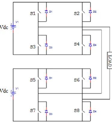
quantity of DC sources is two, a five level output is obtained. The 5 level inverter consists of two H-bridges shown in Fig.1, which are fed by Separate DC sources. There are four switches namely and S1, S2, S3, S4 in the first H-Bridge and there are four more switches namely S5, S6, S7, S8 in the second H-bridge. The load is associated between the terminals A and B. [5]
Fig.1. Five level H-bridge inverter circuit.
The multilevel output voltage can be obtained by closing the appropriate switches mentioned in the switching sequence table1. Example: by opening all the switches, we get zero output voltage across the load. To get Vdc across the load, close the switches S1, S4,S7,S8.
Table 1: Switching Statesof a 5 Level Inverter
III. SIMULATION ANALYSIS
The Simulink model for 5 level H-bridge inverter is developed using MATLAB is as shown in Fig.2. The subsystem pulse generator consists of 8 pulse generators in order to generate the gate pulses for each MOSFET‟s. The delays and pulse widths in each pulse generator are calculated according to the switching pulses.
SWITCHES
Output Voltage
S1 S2 S3 S4 S5 S6 S7 S8
0 0 0 0 0 0 0 0 0
Vdc 1 0 0 1 0 0 1 1
2Vdc 1 0 0 1 1 0 0 1
- Vdc 0 1 1 0 0 0 1 1
Fig. 2. Simulink model of 5 level inverter
INVERTER SPECIFICATIONS:
Input voltage=24V for each h bridge Output voltage= 48 V (for 5 level) Motor: Type: Split phase induction motor 1) Rated Voltage 110V
2) Rated Power (P) 0.25HP
3) Main winding stator resistance 2.02Ω 4) Main winding rotor resistance 4.12Ω
IV. HARDWARE IMPLEMENTATION
Fig.3. Block diagram of experimental setup of 5 level inverter
Table 2: Components used for Hardware Setup:
Sl.No Name of the Component Specification
1 MOSFET IRF250N
2 Step down transformer 0-12V, 5mA
3 Diode IN4007
4 Capacitors 1000µF
5 Opto coupler MCT2E
6 Transistors 2N2222,CK100
7 Buffer HCF4050BE
8 Resistors 100Ω, 1kΩ
9 Micro controller AT89C51
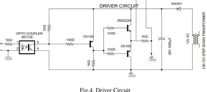
Driver Circuit:
The fundamental motivation behind driver circuit (fig.4) is to improve the switching voltage for the MOSFET or any switching device. And also it gives the isolation between the power circuit and the microcontroller circuit. In this project MCT2E opto-coupler is used, which isolates the power circuit with the microcontroller circuit. Signal from microcontroller is given to the driver circuit.
HARDWARE SPECIFICATIONS:
The complete hardware specification of the proposed 5 level inverter is as follows, 5V Pulses are produced from the micro controller and the driver output is of 12V.
1. For R load:
Input Voltage - 24V for each H-Bridge Output voltage - 48 V
Load - 330kΩ wire wound resistor 2. For Motor load
Input Voltage - 24V for each H-Bridge Output voltage - 30 V
Load- Single phase induction motor-Sewing machine of 220V, 1/12 HP, 70MΩ, 180Mh.
V. SIMULATION AND EXPERIMENTAL RESULTS
With inverter specifications, simulation has been carried out and the output voltage obtained from the Simulink model (fig.2) for R load and RL load was observed from Fig.5 and Fig7, and FFT analysis has been carried out and is as shown in Fig.6.and Fig.8.
Fig.5.Output voltage of 5 level inverter for R load
Fig.7.Output voltage of 5 level inverter for RL load
Fig.8.THD calculation from FFT analysis
Fig.10.Driver circuit Output
Fig.11.Output voltage across R load
Fig.12. output voltage across RL(motor) load
VI. CONCLUSION
REFERENCES
[1] M.H.RASHID “Power Electronics : Circuits, Devices and Applications. Third Edition [2] Bimal K. Bose “Power Electronics and Motor Drives Advances and Trends”. [3] B. Wu, High-Power Converters and AC Drives. Hoboken, NJ, USA: Wiley, 2006.
[4] Yashobanta panda, “Analysis of cascaded multilevel inverter induction motor drives “Department of Electrical Engineering, National Institute of Technology, Rourkela, and Odisha, India
[5] G. Pandian and S. Rama Reddy, “Simulation and analysis of multilevel inverter fed inductionmotor drive” Indian Journal of Science and Technology, Volume: 02 Issue: 04 | May-2010
[6] J. R. Rodríguez, J.-S.-S. Lai, and F. Z. Peng, “Multilevel inverters: A survey of topologies, controls, and applications,” IEEE Trans. Ind. Electron., vol. 49, no. 4, pp. 724–738, Aug. 2002.
[7] E. Sakasegawa and K. Shinohara, “Compensation for neutral point potential in three-level inverter by using motor currents,” Trans. Inst. Elect. Eng. Jpn., vol. 121-D, no. 8, pp. 855–861, 2001.