MATLAB Modeling and Control of Wind
Energy Conversion System
Satyendra Vishwakarma1, Goldy Sharma2
Engineer Trainee, The Hi-Tech Robotic Systemz Ltd, Gurugram, Haryana, India1
Dept. of EEE, Vivekanand College of Technology & Management, Aligarh, U.P., India2
ABSTRACT: The wound rotor induction machine or doubly-fed induction machine has limited applications in the power industry. However, it has become the most popular choice amongst the various wind generator options, especially for large capacity machines. The capability to control the speed of the generator along with controllable power factor has been shown to improve both the efficiency as well as the stability of this generator. This is accomplished by decoupled control of the stator real and reactive powers while the grid side converter maintains the dc bus voltage. This paper discusses the steady-state operation of the DFIG which serves as the foundation for the control of the real and reactive power. The DFIG system is introduced and the various issues concerning the control are discussed.
KEYWORDS: Wind, DFIG, Control, MPPT.
I. INTRODUCTION
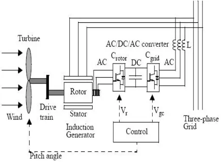
The wind energy conversion system (WECS) using a DFIG is shown in Fig. 1. Two back-to-back voltage source converters connect the stator windings to the rotor windings and a transformer is connected between the grid side converter and the supply. Control of the dc bus voltage is accomplished by the grid side converter while the rotor side converter controls both the speed and the power factor (pf) of the machine. The grid side converter may also deliver reactive power and thus, together with the rotor side converter decreases the generator pf.
Fig. 1 basic diagram of DFIG with converters
electronic control can be used. Reactive power control is an important issue, particularly in WECS which are connected to weak networks. Voltage support capability is often required to maintain the ac voltage within the limits of operation and improve recovery following disturbances and is possible in MV networks when reactive power can be accurately controlled. The DFIG is one type of wind generator which has the ability to compensate the reactive power required by the induction machine [7]
II. TRANSIENT MODELS AND CONTROL OF DFIG
The control of the DFIG consists of two separate control algorithms. The rotor side converter is decoupled control of active power (Ps)and reactive power (Qs) and the grid side control is responsible for regulating the dc bus voltage and
thereby helps the flow of rotor power either to or from the machine, depending on the sign of the slip. Higher-level controls select the real and reactive power references in order to control the speed of the machine and regulate the ac voltage, respectively.
1.1. Power Converter Controls: The two converters are controlled separately using two separate control algorithms. The rotor side control is developed using the steady-state equivalent circuit with proportional integrator (PI) compensation, however closely resembles the control structures as discussed in [1, 3-4]. The grid side control follows from STATCOM or rectifier control theory.
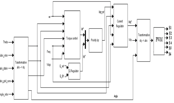
1.2. Rotor Side Converter Control: The real and reactive power control of the stator is realized by the control of the rotor side currents. In effect, active power and reactive powerare first related to the rotor currents and then the rotor currents are controlled through the appropriate gating of the rotor converter. Since control is accomplished on the synchronously rotating frame, this requires both the rotor angle and supply voltage angle for synchronization. The control algorithm is represented in block diagram form in Fig. 2.
Fig. 2 Rotor side converter control
The control sequences are as follows:
a) Measurement of all required quantities including stator voltage, rotor and stator currents, and rotor angle, b) Extraction of the voltage angle using a phase-locked loop (PLL),
c) To perform the appropriate transformations to express all voltage and current quantities on the synchronously rotating frame,
d) Calculation of active power and reactive power,
h) Modulation of the rotor voltages for generation of the gating signals.
In Fig. 2, the rotor angle and speed are measured using an encoder. However, these quantities can be estimated, thereby making the control sensor less, by using electrical transducers [4].
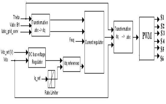
1.3. Grid Side Converter Control: The main purpose of the vector control for the grid side PWM converter is to regulate the DC link voltage. The control system is shown in Fig. 3. This controller consists of a measurement system which measures the d and q axes components of AC currents to be controlled as well as the DC voltage.
Fig. 3 Grid side converter control
1.4. The Model of Current Regulator Control and Dc Voltage Regulator: The current regulator controls the magnitude and phase of the voltage generated by the grid side converter from the reference current produced by the DC voltage regulator and specified q-axis current reference. The grid side converter control consists of generation of d and q current references using the dc voltage error (Iq reference is taken
zero) and the reactive power references, for generation of the gating signals. The complete block diagram of the control is shown in Fig. 4.
Fig. 4 DC Voltage regulator
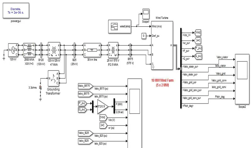
Fig. 5 Simulink model of wind energy conversion system
III. MPPT FOR WIND SYSTEM
To achieve high efficiency in wind power conversion systems, the maximum power point tracking (MPPT) in variable-speed operation systems, like DFIG and PMSG systems, has attracted lots of attention. Basically, the studied techniques in MPPT include three strategies; namely (1) the methods relying on wind speed, (2) the methods relying on output power measurement and calculation, and (3) the methods relying on characteristic power curve. Power electronic devices play an important role in control the converter [6].Before studying these methods and exploring them, the pitch angle power control in DFIG system is briefly introduced to reveal the significance of MPPT and variable speed control [7]. In order for a wind turbine to harvest the maximum amount of energy available from the wind at any given instant, the load applied to the generator needs to be correct for that available energy. This ensures that the maximum power transfer from the wind’s energy to electrical energy is realized. If the load is too large or too small for a particular wind speed, the rotor speed deviates from optimal point and the output power is less.
Fig. 6 Pitch angle control system [8]
b. MPPT Based on Power Characteristic Curve: In recent years, there is a proposed topology of employing the power versus rotor speed characteristic curve, i.e. the reference power curve. Due to the simple idea and without extra wind measurement costs, this method is widely used. The optimal reference power curve is shown in Fig. 7. One could either measure the speed to obtain power reference and then regulate the power, or measure the wind speed to obtain speed reference, and then regulate the speed. The former method produces more accurate output power while the latter has faster control speed. Most research in this method simply apply the cube of rotor speed to generate reference power or the square of rotor speed to generate reference torque, which neglect the exact relationship between maximum power and corresponding rotor speed. Such approximation will obviously lead to inaccurate results. More importantly, analysis is necessary to verify the stability of the method in terms of varying wind speed and output power.
Fig. 7 MPPT based on P-w characteristic curve (a) Regulation of rotor speed ;(b) Regulation of power)
IV. SIMULATION RESULTS
The simulation model of the system has been developed using Matlab R2016b. The system studied under two different conditions, which are discusewd under below:
1) Operating Characteristics at Constant Wind Speed
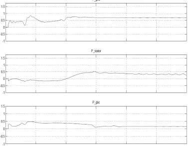
During normal operation, the Grid side converter works as the power regulator and helps the DFIG to supply the required amount of power. The wind generator is able to capture the maximum amount of power and at the same time deliver the dispatched power to the grid. There is no way to interferes with the reactive power control of the generator, which continues to be decoupled from the real component and can be used to support the grid voltage.
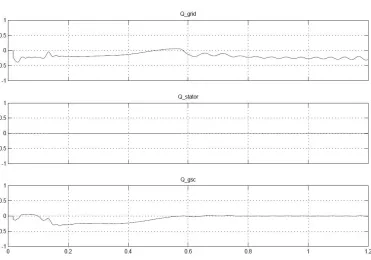
Fig. 8 and Fig. 9 show the real and reactive power flows for the cases of the DFIG with buck-boost converter. It has been observed that DFIG without boost converter the output power fluctuates with the changes in the wind. When the reactive power flow is decoupled from the real power, discrepancies between the reactive power flows can be observed. This is due to change in the terminal voltage caused by real power flows. The reactive power reference is chosen in order to regulate the ac bus voltage. The Q is highly variable when buck-boost converter is absent whereas it is fairly constant in the case with buck-boost converter.
Fig. 9 Reactive power flows for DFIG with boost converter
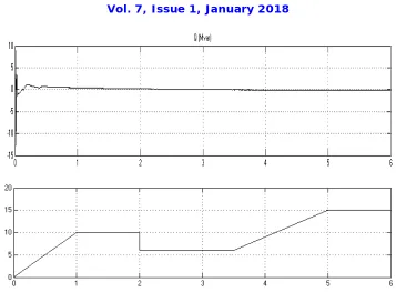
2) Operating Characteristics at Variable Wind Speeds
Fig. 10 Flow of power in variable speed characteristics
V. CONCLUSION
In this paper the steady-state models of the DFIG – Wind energy conversion system have been investigated. It has been shown that the major part of reactive power should be supplied from the rotor side converter in order to reduce the overall kVA rating of the two converters. The rotor side and grid side control models are tested using MATLAB - SimPowerSystems. The control verification has shown that the control principles are reasonable. However, once connected to a realistic power system, which is subjected to typical disturbances, the performance may differ slightly.
REFERENCES
[1] R. Pena, J.C. Clare and G.M. Asher, "Doubly fed induction generator using back to back PWM converters and its application to variable-speed
wind-energy generation" Proc.-Electr. Power Appl., Vol. 143, No. 3, May 1996
[2] Vijay Chand Ganti, Bhim Singh,Shiv Kumar Aggarwal, and Tara Chandra Kandpal "DFIG-Based Wind Power Conversion With Grid Power
Leveling for Reduced Gusts" IEEE Transactions On Sustainable Energy, Vol. 3, No. 1, JANUARY 2012
[3] Morel, L., H. Godfroid, A. Mirzaian, and J.M. Kauffinann, "Double-fed induction machine: converter optimization and field-oriented control
without position sensor", IEE Proc.-Electr. Power Appl., Vol. 145, No. 4, July 1998.
[4] Akagi, H. and H. Sato, "Control and performance of a doubly-fed induction machine intended for a flywhee1 energy storage system," IEEE Transactions Power Elec., Vol.17,No.l,Jan2002.
[5] Datta, R. and V.T. Ranganathan, "A method oftracking the peak power points for a variable speed wind energy conversion system," IEEE Transactions Power Elec., Vol. 16, No. 3, May 2001.
[6] Satyendra V., Goldy Sharma & Mohd Umar, “Importance of Power Electronics in Renewable Energy Systems,” JOURNAL OF INFORMATION,
KNOWLEDGE AND RESEARCH IN ELECTRICAL ENGINEERING, Vol. 02, April 2013.
[7] S. Vishwakarma, G. Sharma & Mohd Umar, “Wind Energy Conversion system,” JOURNAL OF INFORMATION, KNOWLEDGE AND
RESEARCH IN ELECTRICAL ENGINEERING, vol. 02, April 2013.
![Fig. 6 Pitch angle control system [8]](https://thumb-us.123doks.com/thumbv2/123dok_us/7765427.1276509/5.595.201.393.447.698/fig-pitch-angle-control-system.webp)