Modeling and Control of BLDC with P, PI &
Fuzzy Controllers
M.Ramesh Kumar1, G.Vamsi Krishna2, S.Suresh 3
Assistant Professor, Dept. of EEE, MIC College of Technology, Kanchikacherla, Andhra Pradesh, India1
Assistant Professor, Dept. of EEE, MIC College of Technology, Kanchikacherla, Andhra Pradesh, India2
Assistant Professor, Dept. of EEE, MIC College of Technology, Kanchikacherla, Andhra Pradesh, India3
ABSTRACT:Brushless DC Motor (BLDCM) has been widely used in industries because of its properties such as high
efficiency, reliability, high starting torque, less electrical noise and high weight to torque. The dynamic model of the BLDC motor is developed and further analysis has been conducted for the selection of controllers. In this paper, the transient performances of BLDC have been evaluated. The various methods of speed control for Brushless DC Motor has been included and fuzzy controller provide better speed response. MATLAB/SIMULIINK environment is used to carry out the above investigation to select the efficient controller.
KEYWORDS: BLDC Motor. Dynamic Modeling, Speed Control, Fuzzy Controller.
I.INTRODUCTION
A brushless dc motor is defined as a permanent synchronous machine with rotor position feedback. The brushless motors are generally controlled using a three phase power semiconductor bridge. The motor requires a rotor position sensor for starting and for providing proper commutation sequence to turn on the power devices in the inverter bridge. Based on the rotor position, the power devices are commutated sequentially every 60 degrees [11]. Instead of commutating the armature current using brushes, electronic commutation is used for this reason it is an electronic motor. Brushless dc motors are becoming widely used in low power applications such as blower motors, computer disk drive spindle motors, cloth washers, room air conditioners, refrigerators, vacuum cleaners, freezers, copiers and laser printers. These appliances have traditionally relied on classic electric motor technologies such as DC motors, single phase AC induction motors, including split phase, capacitor-start, capacitor–run types, and universal motors [8].
For these applications, the brushless dc motor offers the following advantages: small size, reliability, no carbon dust from brushes, precise speed control, and potentially high efficiency. Reliability and controllability are the two major factors for industrial based motors. These can be achieved through proper choice of controllers. Industrial drives require acute speed control and hence closed loop system with current and speed controllers coupled P, PI controller and fuzzy logic controller. Hence the proper choice of controller is gives a better performance by reducing the problem of overshoot, settling time, and fast response. In this paper, analysis is done to control the speed, and the various parameters such as time of settling, peak overshoot, and steady state error using PI controller and fuzzy logic controller is done and were observed in simulation [10]. Finally the performance comparison between the PI controller and fuzzy logic controller is done.
The advantage of sensorless BLDC motor control is that the sensing part can be omitted and thus overall costs be considerably reduced. Traditionally, the stator resembles that of an induction motor however, the windings are distributed in a different manner. Most BLDC motors have three stator windings connected in star fashion. Each of these windings is constructed with numerous coils interconnected to form a winding. One or more coils are placed in the slots and they are interconnected to make a winding. Each of the windings is distributed over the stator periphery to form an even numbers of poles. There are two types of stator windings variants: trapezoidal and sinusoidal motors. This differentiation is made on the basis of the interconnection of coils in stator windings to give the different types of back Electromotive Force (EMF). The three-phase machine combined with a six-pulse full-bridge inverter often represents the best trade-off of machine iron and copper utilization with the cost of the inverter. Because of the prevalence of two- and three-phase devices, they are the brushless dc motors which have been analysed the most extensively.
II. MATHEMATICAL MODELING OF BLDC MOTOR
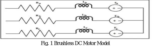
Modeling of a BLDC motor can be developed in the similar manner as a three phase synchronous machine. Since its rotor is mounted with a permanent magnet, some dynamic characteristics are different. Flux linkage from the rotor is dependent upon the magnet. Therefore, saturation of magnetic flux linkage is typically for this kind of motors. The source is not necessary to be sinusoidal [1]. Square wave or other wave-shape can be applied as long as the peak voltage is not exceeded the maximum voltage limit of the motor. Similarly, the model of the armature winding for the BLDC motor is expressed as follows. It is assumed that the BLDC motor is connected to the output of the inverter, while the inverter input terminals are connected to a constant supply voltage, as shown in Fig 1. Another assumption is that there are no power losses in the inverter and the 3phase motor winding is connected in star.
Fig. 1 Brushless DC Motor Model
For a symmetrical winding and balanced system, the voltage equation across the motor winding is as follows: Applying Kirchhoff’s voltage law for the three phase stator loop winding circuit’s yields [3], [7]:
V = R i + L + M + M + e (2.1)
V = R i + L + M + M + e (2.2)
V = R i + L + M + M + e (2.3) Where the back EMF waveforms, e , e , e are functions of angular velocity of the rotor shaft [6],[7], so
e = K w ( ) (2.4) e = K w − (2.5)
e = K w + (2.6) where Ke is the back EMF constant.
Va,Vb,Vc are the phase voltages
ia,ib, ic are the phase currents
Ra, Rb, Rc are the stator winding resistances and is equal to R due to symmetrical winding
La, Lb, Lc are the stator winding inductances and is equal to L due to symmetrical winding
M is the mutual inductance
Electrical and Mechanical angle of rotor can be related as
= (2.7) Where is the electrical angle of rotor
is the mechanical angle of rotor The valve of ( )can be represented as [7]
( ) =
⎩ ⎪ ⎨ ⎪
⎧ 1 0≤ ≤2 3
1− −2 3 2 3≤ ≤
−1 ≤ ≤5 3
−1 + −5 3 5 3≤ ≤2
(2.8)
So the BLDC motor mathematical model can be represented by the following equation in matrix form:
L M M
M L M
M M L
i i i = V V V −
R 0 0
0 R 0
0 0 R
i i i − e e
e (2.9) The electro mechanical torque is expressed as
T −T = J + Bw (2.10) But the electromagnetic torque for this 3-phase BLDC motor is dependent on the current, speed and back-emf waveforms, so the instantaneous electromagnetic torque can be represented as:
= [ + + ] (2.11)
The symbols V, i and e denote the phase voltages, phase currents and phase back-EMF’s respectively, in the three phases a, b and c. the resistance R and the inductance L are per phase values and Te and Tl are the electrical torque and
the load torque. J is the rotor inertia; Kf is a friction constant and wm is the rotor speed. The back-EMF and the
electrical torque can be expressed as respectively; Where Ke and Kt are the back EMF constant and the torque constant.
The electrical angle times the number of pole pairs [7]. The function F gives the trapezoidal waveform of the back-EMF. One period of this function can be written as above. Machine models are often transformed to a rotating reference frame for simplification and to improve computational efficiency. This approach is not used here as it has been shown that when the supply voltage is not sinusoidal, such transformation will not improve computational efficiency.
III. CONTROLLERS FOR BLDC MOTOR
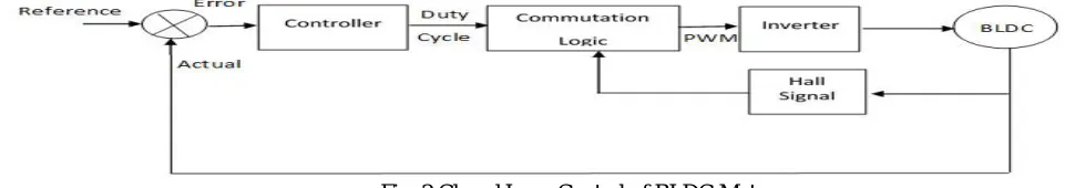
In servo applications position feedback is used in the position feedback loop. A BLDC motor is driven by voltage strokes coupled by rotor position. The rotor position is measured using Hall sensors. By varying the voltage across the motor, we can control the speed of the motor. When using PWM outputs to control the six switches of the three-phase bridge, variation of the motor voltage can be obtained by varying the duty cycle of the PWM signal [9]. The speed and torque of the motor depend on the strength of the magnetic field generated by the energized windings of the motor, which depend on the current through them. Hence adjusting the rotor voltage and current will change motor speed. Commutation ensures only proper rotation of the rotor. The motor speed depends only on the amplitude of the applied voltage. This can be adjusted using PWM technique.
inner current control loop for speed and current control respectively. Speed loop is relatively slower than the current loop.
Fig. 2 Closed Loop Control of BLDC Motor
A. Proportional Controller: In the proportional control algorithm, the controller output is proportional to the error signal, which is the difference between the set point and the process variable. In other words, the output of a proportional controller is the multiplication product of the error signal and the proportional gain. Mathematically, it can be expressed as:
( ) = ( ) (3.1) So if , the Proportional Gain, is very high, the Proportional Band is very small, which means that the Band of Controller Output, over which the final Control Element, like a Control Valve, will go from minimum to maximum (or vice versa) is very small. This is the case with ON-OFF Controllers, where Kp is very high and hence, for even a small
error, the Controller Output is driven from one extreme to another.
B. Proportional and Integral Controller: A proportional integral is control loop feedback mechanism used in industrial control system. In industrial process a PI controller attempts to correct that error between a measured process variable and desired set point by calculating and then outputting corrective action that can adjust the process accordingly. The PI controller calculation involves two separate modes the proportional mode, integral mode [3]. The proportional mode determine the reaction to the current error, integral mode determines the reaction based recent error. The weighted sum of the two modes output as corrective action to the control element. PI controller is widely used in industry due to its ease in design and simple structure. PI controller algorithm can be implemented as
( ) = ( ) + ∫ ( ) (3.2) Where Kp and Ki proportional constant and integral constant respectively.
C. Hysteresis Controller: The Hysteresis current controller contributes to the generation of the switching signals for
the inverter. Hysteresis-band PWM is basically an instantaneous feedback current control method of PWM where the actual current continually tracks the command current continually tracks the command current within hysteresis-band. The control circuit generates the sine reference current and it’s compared with actual phase current wave. The hysteresis current controller can be used for limiting the stator current of BLDC motor within the limit chosen by the hysteresis band limit, which can switch ON/OFF the power switches. The switching patterns are follows [10]:
If >UL, S1 is on and S2 is off. If < LL, S1 is off and S2 is on. If >UL, S3 is on and S4 is off. If < LL, S3 is off and S4 is on. If >UL, S5 is on and S6 is off. If < LL, S5 is off and S6 is on
Where, =current error ( ref. - actual); UL is Upper limit and LL is lower limit of hysteresis band. Depending on the rotor position, the values I*, -I* and zero for three-phase reference currents (ia*, ib*, ic*) are generated and is listed in
the Table-1 [4]. The magnitude of the reference current (I*) is determined by using reference torque (T*) and the back emf constant (Kb) as
Table -1: Rotor position signal Vs Reference Current
Rotor Position Reference Currents (ia*, ib*, ic*)
0°-60° I* -I* 0
60°-120° I* 0 -I*
120°-180° 0 I* -I*
180°-240° -I* I* 0
240°-300° -I* 0 I*
300°-360° 0 -I* I*
Thus the equivalent circuit is obtained for which the method to obtain the reference currents is also discussed above. The speed control which is the main criteria is achieved by implementing proper controller. Here PI controller and fuzzy logic controller were discussed.
IV. FUZZY CONTROL SCHEME
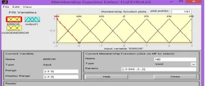
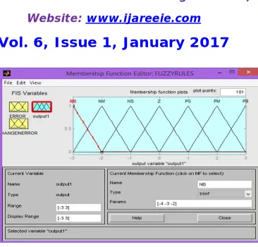
Fuzzy Logic as an program of artificial intelligence is a branch on engineering that concerned with the construction of control programs based on the study of human thinking process, Fuzzy Logic outlook is mainly based on taking decisions with non-specific, uncertain and inaccurate information, it is a power tool to construct complex controllers. It gives a simple control mechanism which is facile to understand and also Fuzzy Logic Controller offer more efficient and controlled performance as compared to conventional control methods. In conventional set theory based on Boolean logic, a particular variable is either a part of a given set or not, on the other hand in fuzzy set theory based on fuzzy logic a particular variable has a degree of membership function that can have any value between range of 0 and 1. To define the shapes of all the membership functions associated with each variable. The range of each membership function is obtained from the knowledge of the system parameter [4]. The fuzzy variable error and change in error has seven sets: positive big (PB), positive medium (PM), positive small (PS), zeros (ZE), and negative small (NS), negative medium (NM) and negative big (NB), with each set having its own membership function. Triangular membership functions are usually used. Mamdani type of fuzzy controller with 49 rules is designed. In our work we use seven membership functions for both input and output. The membership function for error is shown in Fig. 3. The membership function for the change in error is shown in Fig. 4. The membership function for output is shown in Fig. 5.
Fig. 3 Membership Function to error
Fig. 5 Membership Function to Output
The design of a Fuzzy Logic Controller desires the choice of membership function, after a appropriate membership functions are chosen, a rule based should be created, it consists of If-Then rules that completely determines the behavior of the system, these rules very much resembles the human thought process and thus provides artificial intelligence to the system. The rules table is shown in Table-2 and the implemented rules for the control of BLDC Motor with the help of DC link voltage topology in Rule Base Editor is shown in Fig.6.
Table-2 Rules Table to Fuzzy
Fig.6 Rule Base Editor for Fuzzy Logic System E
NL NM NS Z PS PM PL CE
NL NL NL NL NL NM NS Z
V. SIMULATION AND RESULTS
The Simulink model to BLDC using P, PI and Fuzzy controllers and their simulation is carried out in MATLAB/SIMULINK environment. The simulation diagram for BLDC motor speed reference input of 2000 rpm and with different speed control methods are shown Fig. 7.
Fig. 7 Simulink Model for BLDC Motor using P Controller
The Simulink diagram for controller with Praportional is shown in Fig.8
Fig. 8 Simulink Model for P-Controller
The Simulink diagram for controller with Praportional Integral is shown in Fig.9
Fig. 9 Simulink Model for PI-Controller
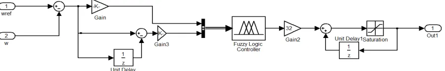
The Simulink diagram for controller with Fuzzy Logic is shown in Fig.10
VI. RESULTS AND DISCUSSION
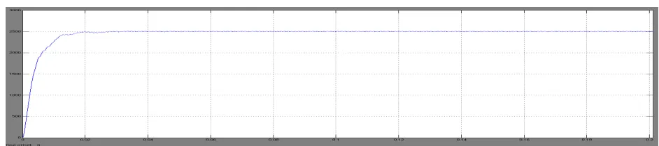
The simulation results for BLDC motor with speed reference input of 2000rpm and with different speed control methods are shown below. The rotor is standstill at time zero with onset of the speed reference, the speed error.
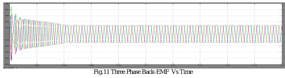
Fig.11 shows the trapezoidal back emf waveform. Here we have considered 120 degree mode of operation.
Fig.11 Three Phase Back-EMF Vs Time
Fig.12 shows the rotor position in degrees with respect to time
Fig.12 Rotor Position in Degrees Vs Time
Fig. 13 shows the closed loop speed response of BLDC motor with P controller
Fig. 13 Speed Vs Time with P-controller
Fig. 14 it shows the closed loop speed response of BLDC motor with PI controller
Fig. 15 it shows the Closed loop control of BLDC motor with Fuzzy controller
Fig.15 Speed Vs Time with FUZZY LOGIC controller
VI. CONCLUSION
A detailed Simulink model for a BLDC Motor drive system with stator current control by using Simulink blocks has been developed and operated at rated speed. Three different control schemes i.e. P (Proportional), PI (Proportional Integral) and Fuzzy Logic control schemes have been developed here. A mathematical model is easily incorporated in the MATLAB simulation and the presence of numerous tool boxes and support guides simplifies the simulation of large control system. The output waveform for speed with different controllers proves that Fuzzy Logic controllers are better than P, PI controllers. The simulation with Fuzzy Logic controller allows faster simulations with reduced time and computational resources. A speed controller has been designed successfully for closed loop operation of the BLDC Motor drive system so that the motor runs at the reference or commanded speed. The modelled simulated system has a fast response with least error thus validating the design method of the speed controller.
REFERENCES
[1] P. Pillay, R. Krishnan, “Modelling, Simulation and Analysis of Permanent-Magnet Motor Drives Part II: The Brushless DC Motor Drive”, IEEE Transaction on Industry Applications, pp. 274-279, September 2008
[2] Santanu Kumar Nayak, Pallav Dutta, “A Comparative Study of Speed Control of DC Brushless Motor Using PI and Fuzzy Controller”, IEEE Transactions on Industrial Electronics, Vol. 15, No. 2, 2015.
[3] Md Mustafa Kamal, Lini Mathew,”Speed Control of Brushless DC Motor Using Fuzzy Based Controllers”, IEEE Students’ Conference on Electrical, Electronics and Computer Science, Vol. 14, No. 1, 2014.
[4] Madhusudan Singh, Archana Garg,“Performance Evaluation of BLDC Motor with Conventional PI and Fuzzy Speed Controller”, IEEE Transactions on Industrial Electronics, Vol. 12, No. 9, 2012.
[5] M. Surya Kalavathi, C. Subba Rami Reddy,“Performance Evaluation of Classical and Fuzzy Logic Control Techniques for Brushless DC Motor Drive”, IEEE Transactions on Industrial Electronics, Vol 12, No 7, 2012, pp. 488-491.
[6] Neethu U., Jisha V. R.,“Speed Control of Brushless DC Motor : A Comparative Study”, IEEE International Conference on Power Electronics, Drives and Energy Systems, Vol. 8, No. 12, 16-19 December 2012, Bengaluru India.
[7] C. P. Singh, SS Kulkarni, S.C. Rana, Kapil Deo, Scientists, “State-Space Based Simulink Modeling of BLDC Motor and its Speed Control using Fuzzy PID Controller” IJAEST, Volume 2 , Number 3, pp.359-369,
[8] Preetha Philip, Dr. Meenakshy K, “Modelling of Brushless DC Motor Drive Using Sensored and Sensorless Control (back EMF zero crossing detection)”, IJETAE, Volume 2, Issue 8, August 2012.
[9] vinod Kr Singh Patel, A.K.Pandey, “Modeling and Simulation of Brushless DC Motor Using PWM Control Technique”, IJERA, Volume 3, ssue 3, pp.612-620, May-Jun 2013.
[10] S. Iyappan, M. Vijayalakshmi, R. Ramaprabha, “Analysis of Controllers for Speed Control in Brushless DC Motor Using MATLAB” IJETAE, Volume 4, Issue 11, pp.467-473, November 2014.