ISSN (Print) : 2320 – 3765 ISSN (Online): 2278 – 8875
I
nternational
J
ournal of
A
dvanced
R
esearch in
E
lectrical,
E
lectronics and
I
nstrumentation
E
ngineering
(An ISO 3297: 2007 Certified Organization)
Vol. 4, Issue 2, February 2015
Implementation of Distributed Maximum
Power Point Tracking for Partially Shaded PV
Systems
J.Vinoth1, T.Muthukumar2, Dr.M.Muruganandam3
PG Student, Dept. of EEE, Muthayammal Engineering College, Rasipuram, Tamilnadu, India1
Assistant Professor, Dept. of EEE, Muthayammal Engineering College, Rasipuram, Tamilnadu, India2
Professor, Dept. of EEE, Muthayammal Engineering College, Rasipuram, Tamilnadu, India3
ABSTRACT: In normal MPPT controlling methods, all the PV panels are connected to single MPPT to produce maximum output. If any fault occurs in the PV Panel or less irradiance in some part of the panel (partially shaded PV system) also leads to reduction in power generation. In the proposed system the efficiency is increased for partially shaded PV system by using “distributed” MPPT (DMPPT) technique. In this method each panel is connected separately to separate MPPT. Each MPPT is connected to the Buck-Boost converter to compensate the voltage variation in the different PV panel. Finally all the MPPT’s are connected in parallel which increases the power production and efficiency.
KEYWORDS: DMPPT technique, Buck boost converter, Photovoltaic System
I. INTRODUCTION
A Solar Photovoltaic (PV) Cell converts the solar radiation into electrical energy. This is the most popular method of power generation in recent days. The solar power should be utilized very effectively because it gives only 20-25 years of lifespan. The real challenging task of this method is tracking the maximum power point as it provides many peak powers at different times. To track the maximum power of the PV panel the maximum power point technique (MPPT) is used in the solar system [2].
The different MPPT techniques are used in Solar like Perturb & Observe, Incremental conductance etc. They calculate the present and past voltage and current to track the exact maximum power. They compare the values and find the MPP and generate the duty cycle to drive the buck-boost converter. Conventional MPPT technique is inefficient during the mismatches in the irradiance at the PV panel. This mismatch occurs due to the partially shaded condition which happens because of shadows of trees, clouds, overhead lines, buildings, etc. [3-7]. This partially shaded condition will result in the reduction of power production. If the PV panels are connected in series during the partially shaded condition the output power of the whole PV system will be affected. This leads to more losses which reduces the efficiency of the system. [8-12]
ISSN (Print) : 2320 – 3765 ISSN (Online): 2278 – 8875
I
nternational
J
ournal of
A
dvanced
R
esearch in
E
lectrical,
E
lectronics and
I
nstrumentation
E
ngineering
(An ISO 3297: 2007 Certified Organization)
Vol. 4, Issue 2, February 2015
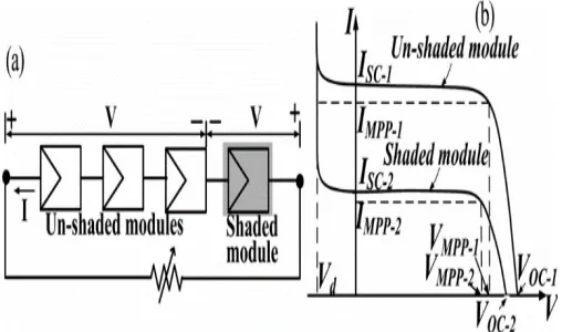
Fig.1 (a) Series connected PV panels (b) I-V Characteristics of shaded and un-shaded PV panels
II. BLOCK DIAGRAM
Existing System:
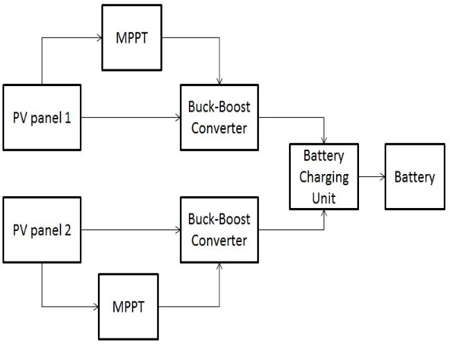
The generation of power through solar energy requires more than one photovoltaic panel connected in series and parallel to each other to make a solar system. The MPPT is used for the system to track the point at which the maximum power is obtained. In existing system the MPPT is used in common for all the PV panels that are connected in series as well as in parallel. If the irradiation from the sun is constant over all the panels it will provide an efficient output. But when the irradiation from the sun changes for different panels due to the passing clouds, shadow of buildings, crossing of birds, etc., will leads to variation of output from each panel. So the final output will not be efficient and further it may not be helpful for the commercial usage due to the fluctuations created in the output. This problem also will reduce the lifetime of the PV panels.
Fig. 2 Block diagram for existing system
Proposed System:
ISSN (Print) : 2320 – 3765 ISSN (Online): 2278 – 8875
I
nternational
J
ournal of
A
dvanced
R
esearch in
E
lectrical,
E
lectronics and
I
nstrumentation
E
ngineering
(An ISO 3297: 2007 Certified Organization)
Vol. 4, Issue 2, February 2015
the battery charging unit that gives required voltage to charge the battery. By using this technique the duration of the power generation is also can be increased. The response of the MPPT technique will be faster as separate MPPT is used which provides more accuracy.
Fig. 3 Block diagram for existing system
III. SEGMENTS USED
During Partially shaded condition, the output power decreases as the current generated from the series connected PV module is reduced. This is due to the lower current flow in the partially shaded module. This prevents the unshaded module to prevent the system from delivering full power output. The shaded module gets reversed biased depends on the load requirements resulting in the rise of temperature and formation of local hotspot, which will damage the PV panel and reduce the efficiency of the PV panel output.
DMPPT:
DMPPT will provide the maximum power during the partially shaded condition. The power output with the help of DMPPT is obtained based on the module level but not the array level. In normal PV panel operation, single MPPT is connected to a whole PV panel so the output is reduced during the partially shaded condition. To overcome this problem DMPPT method is introduced [5]. Distributed MPPT is nothing but MPPT is connected to each and every panel separately. Thus the voltage difference can be corrected in each module which gives almost similar voltage output at all PV panel. Because of the constant output at all the PV panels the efficiency of the system is been increased with DMPPT. All the panels are connected in parallel to each other to combine the output.
BUCK-BOOST CONVERTER:
ISSN (Print) : 2320 – 3765 ISSN (Online): 2278 – 8875
I
nternational
J
ournal of
A
dvanced
R
esearch in
E
lectrical,
E
lectronics and
I
nstrumentation
E
ngineering
(An ISO 3297: 2007 Certified Organization)
Vol. 4, Issue 2, February 2015
Fig.4. Buck-Boost Converter
The operation of buck-boost converter is as follows. During On-state condition (switch ON), the inductor L is connected directly to the input voltage source, where inductor L will store energy and the load is supplied by the energy which is stored in the capacitor. During Off-state condition (switch OFF), the energy that is stored in the inductor L is transferred to capacitor C and load. The relation between input and output voltage is given as
MPPT Techniques:
There are different algorithms in performing the MPPT Techniques. Few of which is Perturb & Observe (P&O) algorithm, Incremental Conductance algorithm, Current sweep method, Constant voltage, etc., to find the point at which the maximum power is obtained [2].
Perturb& Observe:
The Perturb & Observe (P&O) algorithm is one of the algorithms which are used in MPPT techniques. It is also known as “Hill-climbing” technique. In this method, the power is measured and the voltage is controlled in the array. As the power varies the adjustment is made so as to reduce the change in power. This method only needs the voltage to calculate the maximum power point. The implementation of this method is easier method to find the maximum power point since it needs only the voltage value [9].
Fig.5. Flowchart of P&O algorithm
ISSN (Print) : 2320 – 3765 ISSN (Online): 2278 – 8875
I
nternational
J
ournal of
A
dvanced
R
esearch in
E
lectrical,
E
lectronics and
I
nstrumentation
E
ngineering
(An ISO 3297: 2007 Certified Organization)
Vol. 4, Issue 2, February 2015
less when compared to incremental conductance method but this method is preferred because of its easier implementation.
Battery charger Unit:
It consists of boost converter and the controller in it. The boost converter is used to increase the output voltage which is capable of charging the battery. This maintains the voltage as constant value even there is the change in the voltage from the output of the PV panel.
Fig.6. Simulation diagram of battery charging unit
The controller in the battery charging unit collects the output voltage information and kept it as a feedback to control the output voltage. The controller unit gets the current and voltage input and provides duty cycle to drive the boost converter for maintaining the constant output to charge the battery. The PWM generator is generates the pulse that is used to trigger the buck-boost converter. The output is maintained constant with the help of this converter.
IV. SIMULATION DIAGRAMS
Fig.7. Main simulation diagram
ISSN (Print) : 2320 – 3765 ISSN (Online): 2278 – 8875
I
nternational
J
ournal of
A
dvanced
R
esearch in
E
lectrical,
E
lectronics and
I
nstrumentation
E
ngineering
(An ISO 3297: 2007 Certified Organization)
Vol. 4, Issue 2, February 2015
MPPT provides certain duty cycle so as to maintain constant output at both the PV modules. The EMI filter is used to reduce the ripple in the DC output generated from the solar PV panel. The battery charger unit is placed after the EMI filter which is used to provide the required voltage that is needed to charge the battery. The boost converter is used to increase the voltage level of the output in the battery charger unit.
PV Panel Module Subsystem:
The current is generated from the PV panel while the voltage is produced with the help of the controlled current sensor. Both the current and the voltage value is measured and given to the input to the MPPT which also has the timer input that gives the information to the MPPT about how frequently the voltage and the current has to be measured from the solar panel. Finally by analysing the voltage and the current value the duty cycle is created so as to trigger the buck-boost converter. This buck-buck-boost converter either increments or decrements the output values which is obtained from the PV panel according to the reference voltage that is defined.
Two similar panels are connected in parallel to each other. The output is obtained at each panel. Since each panel are provided with the separate MPPT, during the changes of the irradiation occurs due to natural causes in the different panel the MPPT that is connected separately to each panel will provide duty cycle to corresponding buck-boost converter to produce constant output voltage.
Fig.8. Simulation diagram of PV Panel
V. SIMULATION RESULTS
The simulation results for the proposed system are obtained as follows. The output voltage is measured across the output terminal. The voltage obtained from it is to be capable for charging the battery. In the proposed system a 48V battery is used. To charge the 48V battery, the required input voltage to the battery has to be about 54V. Thus the battery charging unit is created and the voltage is boosted up to meet the requirement for charging the battery.
ISSN (Print) : 2320 – 3765 ISSN (Online): 2278 – 8875
I
nternational
J
ournal of
A
dvanced
R
esearch in
E
lectrical,
E
lectronics and
I
nstrumentation
E
ngineering
(An ISO 3297: 2007 Certified Organization)
Vol. 4, Issue 2, February 2015
The above output is obtained for the first PV panel which has the irradiation of 1 and temperature of 27oC. The output voltage for this PV panel is obtained of about 26V and the current is obtained as 8.8A. This output is boosted up by the buck-boost converter that is provided to it for getting the constant output voltage even during variation in the irradiance obtained from the sun.
The output for the second PV panel is obtained as shown below. The irradiance of 0.5 and temperature of 27oC is given to second panel and the output voltage is obtained at the range of 16V while the current is obtained as 4.4A. Since the irradiance is less in this panel, the output voltage is reduced according to the variation. These variations will result in the reduction of the efficiency of the system. So the buck-boost converter is used to boost the output voltage to a constant level at both the PV panels. Now the output from both the PV panels is similar to each other.
Fig.10. PV panel 2 output
As the panels are connected in parallel to each other they are combined together and the resultant output is obtained as follows.
Fig.11. Output voltage of parallel connected PV panel
After connecting both the PV panel in parallel, the output voltage is obtained nearly 45V. But this output voltage is not enough to charge 48V battery, so the battery charging unit is used after the PV panels to regulate the output voltage. The boost converter is used as a part of battery charging unit to increase the output voltage to meet the requirement for charging the battery.
ISSN (Print) : 2320 – 3765 ISSN (Online): 2278 – 8875
I
nternational
J
ournal of
A
dvanced
R
esearch in
E
lectrical,
E
lectronics and
I
nstrumentation
E
ngineering
(An ISO 3297: 2007 Certified Organization)
Vol. 4, Issue 2, February 2015
of about 54V is reached after the boost converter. The output is stable at this range which required for charging the battery.
Fig.12. Overall output voltage
VI. CONCLUSION
The Distributed Maximum Power Point Tracking (DMPPT) technique is used in this paper which gives more efficiency than the normal MPPT method. The usage of separate MPPT for each and every PV panel will control the output of each PV panel and boost the output to a constant voltage even there is a change in irradiation. Such process provides the same output at all the PV panel which provides stable output. Due to this, the final output can be controlled easily and provides the constant output voltage throughout the process. The battery is used to store the energy that is generated from the PV panel. To charge the battery it requires almost constant output to avoid the damage of battery. The usage of normal MPPT technique will not result in the constant output during partially shaded condition. But the implementation of DMPPT technique yields the constant output voltage to charge the battery.
REFERENCES
1. Pooja Sharma and Vivekagarwal, “Exact maximum power point tracking of grid connected partially shaded PV source using current compensation concept”, IEEE transactions on Power Electronics, Vol.29, No.9, Sep,2014.
2. M.Muruganandam and M.Madheswaran, “Hybrid PID-ANN Controller for Closed Loop Control of Chopper fed DC Series Motor” has been presented the Second International Conference on Interdisciplinary Research and Development, INRIT2012, 1st June 2012, Thailand.
3. H. Patel and V. Agarwal, “Maximum power point tracking scheme for PV systems operating under partially shaded conditions”, IEEE Trans. Ind. Electron, Vol.55,No4, April,2008
4. M.Muruganandam, M.Madheswaran, “Simulation and Implementation of Generalized Hybrid Intelligent Controllers for Chopper fed DC Series Motor” Published in International Journal of Wulfenia, Volume 19, Issue 12, December 2012, Page(s):313-335. ISSN: 1561-882X
5. M.Kirubavathi, G.Dineshkumar and M.Muruganandam, “Fault Current and Over Voltage Limitation in a Distribution Network with Distributed Generation Units through Superconduction Fault Current Limiter” Published in International Journal of Engineering Research and Technology, Volume 3, Issue 11, November 2014, Page(s):1442-1445, ISSN: 2278-0181
6. M.E. Herniter and W.J. Schlanger, “Battery charger with maximum power point tracking”, US patent 6 057 665, May,2000
7. Nicola Femia, Giovanni Spagnuolo and Massimo Vitelli, “Distributed maximum power point tracking of photovoltaic arrays: Novel approach and system analysis”,IEEETtrans. Ind. Electron, Vol.55,No7,July,2008
8. C Nagarajan, M Muruganandam, D Ramasubramanian, “Analysis and Design of CLL Resonant Converter for Solar Panel-battery Systems”, International Journal of Intelligent Systems and Applications (IJISA), Volume 1, December 2012 pp 52-58.
9. C.Nagarajan and M.Madheswaran - ‘Performance Analysis of LCL-T Resonant Converter with Fuzzy/PID Using State Space Analysis”- Springer,
Electrical Engineering, Vol.93,March 2011.
10. S.Saranraj, A.Sasipriya , S.Ramkumar and M.Muruganandam, “A voltage controlled PFC SEPIC converter based PMBLDC motor drive for Air-Conditioners using Fuzzy controller”, IJAIR, Volume.3, Issue.9, 2014
11. Young-HyokJi, Doo-Yong Jung, et.al., “A real maximum power point tracking method for mismatching compensation in PV array under partially shaded conditions”, IEEE Trans. Power Electronics, Vol.26,No4, April,2011
12. N. Femia, G.Petrone and G.Spagnuolo, “Optimization of perturb and observe maximum power point tracking method”, IEEE Trans. Power Electronics, Vol.20,No4, July,2005
13. M.G.Jaboori, M.M.Saied and A.R. Hanafy, “A contribution to the simulation and design optimization of photovoltaic systems”, IEEE Trans. Energy Converter, Vol.6, no.3