An Adaptive Control Technique for Parallel
DC Boost Converters Used in PV Power
Generating System
Reshma Mary Thomas1, Deepu Jose2
PG Student [Power Systems], Dept. of EEE, Saintgits Engineering College, Kottayam, Kerala, India1 Assistant Professor, Dept. of EEE, Saintgits Engineering College, Kottayam, Kerala, India2
ABSTRACT: The rising rate of consumption and price of fossil fuel along with environmental pollution by conventional power generation draw global attention to renewable energy sources and technology. Paper gives analysis study on current sharing issues of parallel DC converters in standalone photovoltaic (PV) system. Project simulation of incremental conductance for maximum power point tracking (MPPT) used in solar power systems has been done . The main drawbacks of parallel converters are poor power sharing and voltage drop. The paper describes about instantaneous droop calculation considering effect of cable resistance using droop index to improve the power sharing performance. The control technique is simulated using MATLAB/SIMULINK in PV power generating system with MPPT and case study has been done on the control strategy and verify the effectiveness of adaptive droop control on output converter voltage .
KEYWORDS: Microgrid; droop method; incremental conductance (Incond); maximum power point tracking (MPPT).
I.INTRODUCTION
Expensive technologies and global environmental damage techniques has led to a global scenario which point to generating clean and eco-friendly green energy. Due to the rate of depletion of conventional energy sources, countries have begin to emphasize on generating power through renewable sources such as wind energy, solar energy,tidal energy etc. For example nation like India has set a mission to deploy 20,000 MW of grid connected solar power by 2022. The growth of renewable energy has changed energy business in India. In many ways, it is having a leading role in the democratized energy production and consumption of the country. Of all the renewable energy sources , solar energy have the least impact on environmental damage. Electricity produced from photovoltaic (PV) cells does not result in environmental pollution, deplete natural resources, or endanger living being [1].
For many years, the centralized power grid is one way of electricity flow, generated by large, remote power plants and distributed over large distance by transmission lines to homes and industries. In recent years the system’s shortcomings are increasing. The traditional grid is highly depends on planet-warming fossil fuels. Due to the upcoming of negative issues there is departing from the traditional system and introduced a new model called Microgrid. A microgrid is defined by the ability to generate power using renewable energy sources near or at the point of consumption independent of other generators. Main applications are in areas having high energy prices or remote areas (such as islands) or facilities, such as military or experimental installations that cannot risk losing power, etc. Microgrid, also named as minigrids, can be operated in islanded or grid connected mode. Compared to AC, DC microgrids are very reliable highly efficient, economic and easy to control.
ISSN (Print) : 2320 – 3765 ISSN (Online): 2278 – 8875
I
nternational
J
ournal of
A
dvanced
R
esearch in
E
lectrical,
E
lectronics and
I
nstrumentation
E
ngineering
(An ISO 3297: 2007 Certified Organization)
Vol. 4, Issue 10, October 2015
control method. This paper mainly focus on the voltage control and power sharing of the converters using droop index and also maximum power point tracking for better performance.
The droop control method is a decentralized control technique in which each converter is controlled based on the output current [7]. This paper explains the importance of cable resistance in load sharing. In existing methods the droop used for voltage control is fixed which a major drawback [5]. An instantaneous droop is calculated to overcome this drawback which can improve the voltage control to larger extend.
The solar cell efficiency depends on factors such as temperature, radiation, shadow, and so on. Due to fast changing climate such as cloudy or sunny day there will be changes in irradiance on solar panels and rise in temperature can decrease the PV array output power. PV cell produces energy depending to its operational and environmental conditions. Maximum power point tracking (MPPT) is a concept put forward to improve the efficiency of PV. All MPPT methods follow goal of maximizing the PV power output by tracking the maximum on all operating condition. Analysis study and case study of the droop control method for voltage regulation and MPPT method is explained.
II. SOLAR SYSTEM MODEL
A. Solar Cell
The basic unit of solar module is PV cells. A solar cell converts light energy into electricity by photoelectric phenomenon. A single solar cell can produce only small amount of energy. To increase the output power of the system, solar cells are usually connected in parallel or series to form PV. The main equation of the output current of a module is
I = npIpℎ−npIrs exp k0 −1 (1) where Io is output PV current, is the output PV voltage, cell photocurrent, Irs , solar cell reverse saturation current
Iph which is proportional to solar irradiation, that mainly depends on surounding temperature, np represents number of cell connected in parallel and ns represent the number of series connected PV cells, ko is constant.
I
pℎ= [I
scr+ k
i(T
−
T
r)]
(2) Where ki SC current temperature coefficient; Tr cell reference temperature; S is the solar irradiation; Iscr, solar cell short-circuit current ;. Moreover, the cell reverse saturation current is calculated fromIrs = Irr exp − (3)
Irr reverse saturation at Tr; EG band gap energy of the semiconductor used in solar cell. A MPPT has high-efficiency DC-DC converter, which functions as an excellent electrical load for PV cell, most commonly used for solar panel and converts the power to a voltage or current level which is more suitable. PV cells have single operating point where the current and voltage values result in a maximum power output. MPPT controls the duty cycle circuit of the DC converter to enable the PV module to operate at maximum output power at all operating condition. The main advantages of MPPT are excellent during cloudy or hazy days or cold weather. There are different types of MPPT methods developed are (1) Incremental conductance method, (2) Perturb and observe method, (3) Artificial neutral network method.
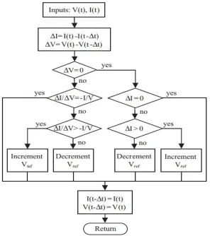
B. Incremental Conductance Method
Fig 1. Algorithm of Incremental Cond method The maximum output power,
= (4) is calculated by differentiating PV output power with respect to voltage and then setting the result to zero.Applying the chain rule for the derivative of products yields to ∂P/∂V = [∂(VI)]/∂V.
At MPP, as ∂P/∂V=0. This equation can be written in terms of array voltage V and current I as
= -
In this method the peak power of the solar module lies at above 98% of its incremental conductance.
III. PARALLEL DC BOOST CONVERTERS
The DC-DC boost converters are used in applications where the required output voltage needed to be higher than the source voltage. The control technique used is sliding mode control. Sliding mode controller maintain stability and consistence performance in the face of modeling imprecision. Control gains used are 0.149 and 1.35.
TABLE 1:DC-DC BOOST CONVERTER PARAMETERS Parameters Values
Output power 96 Output voltage 48
Filter inductor 710 µH ESR of filter Inductor 0.03Ω
Filter capacitor 2220µF ESR of filter capacitor 0.05Ω
Nominal switching frequency
100kHz
A. Mathematical Analysis Of Circulating Current For Two Parallel Connected Converters
ISSN (Print) : 2320 – 3765 ISSN (Online): 2278 – 8875
I
nternational
J
ournal of
A
dvanced
R
esearch in
E
lectrical,
E
lectronics and
I
nstrumentation
E
ngineering
(An ISO 3297: 2007 Certified Organization)
Vol. 4, Issue 10, October 2015
using , 2
,
1 and ,and respectively. is the circulating current component from converter-1 to converter-2 and load current component from converter-1 is
′
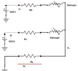
.Fig 2. Equivalent circuit for DC output side
By applying Kirchhoff’s voltage law, the expression for output converter currents can be derived from equation and circulating current can be calculated.
− − = 0 (5)
− − = 0. (6) The expression for output converter currents
and can be derived from equation (5) and (6) and circulating current is given as:
=
( ) ( ) (7)=
( ) ( ) (8)=
=
=
(
=
)
(9)IV. VOLTAGE REGULATION AND CIRCULATING CURRENT CONTROL BY FIXED DROOP METHOD
This section explains converter voltage regulation and minimization of circulating current by adding a series resistor, Rdroopto each converter output as shown in Fig.2. Rdroop is implemented using virtual impedance method. Fig4. By adding Rdroop1and Rdroop2 the current sharing can be controlled and thus circulating currents can be minimized to some extent. This can be done by taking output current from converters and multiplied with corresponding Rdroop .
Then the resultant signal is subtracted from the reference voltage of each corresponding converter give new voltage reference signal .
= – I (10) But this method has still got drawbacks as it’s a fixed value and therefore the voltage regulation will be poor.
A. Adaptive Droop Control Method
Fig 3.Equivalent circuit for DC output side with Rdroop
As we have seen in above equation (9) in two parallel converters, circulating current directly proportional to the current sharing difference. If the current sharing is equal then the resultant circulating current becomes zero. There will constant output voltage from converters. But simultaneous insertion of the series resistor will cause additional power loss in the system and it will leads to drop in the load voltage. Rdroop1and Rdroop2 are corresponding droop value of each converter. The output power loss can be expressed as,
= ( +
) +
( +)
(11) Calculation of droop values based on the proposed figure-of-merit called droop index. The droop index is considered function of normalized current sharing difference and output power losses based on the need of voltage regulation issues and are given asDroop Index = min [
|
−
|
+(
)
] (12) The current sharing and power loss equation can be modified in terms of parameters of second converter by introducing new variables x, y and m and given as=
,=
,=
+
|
−
|
=|
( )( )
|
(13)Using the modified equation of circulating current and power loss the minimum droop index is calculated.
value for corressponding converter is selected in such way that , it is varied from zero and corresponding droop inex value is noted and value for minmum droop index is selected for further procedure. For the calculation of minimum droop index by varying , the product of converter output current and should not increase the maximum allowable voltage deviation (± 5% nominal voltage).
value for minimum droop index value of converter-2 is droop value. Now the droop value for converter 1 can be calculated using
= (14) The calculated droop value is may not be enough for voltage regulation. Therefore fine tuning of value is required to make the output voltage same but since the value is positive further increase will cause poor load voltage. To avoid this problem shifting is done. Shifting is done bases of the converter output value.
If the difference between converter output voltage is positive then ie;
ISSN (Print) : 2320 – 3765 ISSN (Online): 2278 – 8875
I
nternational
J
ournal of
A
dvanced
R
esearch in
E
lectrical,
E
lectronics and
I
nstrumentation
E
ngineering
(An ISO 3297: 2007 Certified Organization)
Vol. 4, Issue 10, October 2015
<
then ,=
−
(
∗
)
=
+ (
∗
)
(16) And if the converter output voltage values are equal then the corresponding droop values same as before. The droop correction factor and (0.001 and 0.02 respectively) should be selected such that<
to maintain load voltage within the limit.V. SIMULATION AND RESULTS
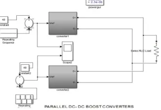
To check the performance of the droop control method in different cases, two parallel DC –DC boost converters (24V-48V) with solar energy as source has been simulated using MATLAB/SIMULINK. The output cable resistance is 100mΩ for each converter. The control algorithm is verified for the following cases, (i) Step change in output voltage of any one converter with both converters with same cable resistance(a) without droop control Fig.4. (b) with
control method.Fig.6.
Fig.4. Simulink Model of Parallel converters without Droop
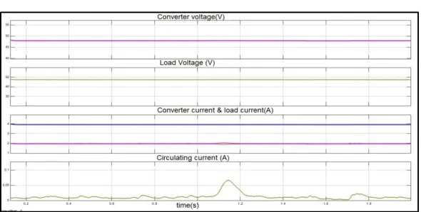
Initially up to 1.101s the simulation is done with nominal value, 48V. During time 1.101-1.3s the converter2 voltage value is increase by 1% of nominal value, 48.48V and at time 1.301s the voltage is brought back to 48V. Then again during time 1.501-1.7s the value is decreased by 1 % of the nominal value, 47.52 V
Fig 5. Simulation Result of without droop (a) converter output voltages and load voltage (b) converter output current and load current (c) circulating current.
TABLE 2: SIMULATION RESULTS WITHOUT DROOP
Time
Output values
Vdc1,Vdc2,Vl (V)
I1,I2,Il (A)
|Ic12| (A)
0 -1.101 48,48,47.5 2,2,4 0 1.101-1.3 48,48.48,47.4 0.1,3.9,4 1.9 1.501 -1.7 48,47.52,47.4 3.9,0.1,4 1.9
For simulation with novel droop control method, the and values are calculated as 0.2Ω and still
there is mismatch output converter voltage. After fine tuning of voltage is not regulated completely. Then instantaneous value of is introduced with droop shifting which can improve the current sharing and the output converter voltage to a constant.
Fig.6.Simulink Model with Droop Control
The same simulation pattern as that of the without droop case is follwed here as well and simulation results are analysed. From the results it can be noted that the current sharing error has been reduced considerably.
TABLE3: SIMULATION RESULT WITH DROOP CONTROL.
Time
Output values
Vdc1,Vdc2,Vl
(V) I1,I2,Il (A) |Ic12| (A)
ISSN (Print) : 2320 – 3765 ISSN (Online): 2278 – 8875
I
nternational
J
ournal of
A
dvanced
R
esearch in
E
lectrical,
E
lectronics and
I
nstrumentation
E
ngineering
(An ISO 3297: 2007 Certified Organization)
Vol. 4, Issue 10, October 2015
Fig 7. Simulation Result of with droop (a) converter output voltages (b) load voltage (c) converter output current and load current (d) circulating current.
From the above simulation studies, it can be seen that droop control method gives proper load sharing with minimum circulating current and improves load voltage. By improving current sharing we can see that the power sharing has also been improved. Here, from the graphs it is obsereved that the circulating current has been reduced to 0.1 A from 1.9 A.
VI.CONCLUSION
The performance of droop control method for parallel DC-DC converter used in standalone photovoltaic system is studied in different cases. The entire energy conversion system has been designed in MATLAB/SIMULINK environment. Incremental conductance method of MPPT is used to track maximum output. The parallel DC- DC boost converters with sliding mode control technique is used. The Rdroop values are calculated considering the effect cable
resistance and implemented using virtual impedance method. For different irradiation of PV array the droop control is tested and verified. Based on the instantaneous condition the new Rdroop value is introduced into the system, which will
minimize the circulating current and gives proper sharing. This droop control technique can be used with any number of parallel connected converters.
REFERENCES
[1] S.. Bull, “Renewable energy today and tomorrow,” Proc. IEEE, vol. 89, no. 8, pp. 1216–1226, Aug. 2001.
[2]. C. Hua and C. Shen, "Study of maximum power tracking techniques and control of DC/DC converters for photovoltaic power system," 29th Annual IEEE Power Electronics Specialists Conference, pp. 86 - 93, 1998.
[3]. Y. Chuanan and Y. Yongchang, "An Improved Hill-Climbing Method for the Maximum Power Point Tracking in photovoltaic System," IEEE International Conference on Machine Vision and Human-Machine Interface, pp. 530 - 533 2010.
[4]. S. Augustine, M. K. Mishra, and N. Lakshminarasamma, “Circulating current minimization and current sharing control of parallel boost converters based on droop index,” in Proc. IEEE SDEMPED Conf., Aug. 2013, pp. 454–460.