Volume 4, No. 10, September-October 2013
International Journal of Advanced Research in Computer Science
RESEARCH PAPER
Available Online at www.ijarcs.info
ISSN No. 0976-5697
Reduced Hardware Cordic Based 16 Point Fft Processor
Mushina A A*M.Tech Student, Department of ECE, Nehru College of Engineering and Research Centre, Pampady,
Thiruvilawamala, Kerala, India. [email protected]
Siby T Y
Assistant Professor, Department of ECE, Nehru College of Engineering and Research Centre, Pampady,
Thiruvilawamala, Kerala, India. [email protected]
Parameshachari B D
Associate Professor, Department of ECE, Nehru College of Engineering and Research Centre, Pampady,
Thiruvilawamala, Kerala, India. [email protected]
Athira V R
Assistant Professor, Department of ECE, Nehru College of Engineering and Research Centre, Pampady,
Thiruvilawamala, Kerala, India.
H S DivakaraMurthy Dean and HOD, Department of ECE,
Nehru College of Engineering and Research Centre, Pampady, Thiruvilawamala, Kerala, India.
Abstract: This project presents a 16 point FFT processor based on a Reduced Hardware CORDIC Algorithm. The proposed algorithm utilizes a new rotation scheme which uses only two angles as the rotation angles. In this proposed scheme, we do not want to store the twiddle angles. Thus there is reduction in the number of hardwares required, which results in a considerable reduction in the power and total memory used. Then the performance of 16 point FFT processor based on proposed reduced hardware CORDIC algorithm is compared with 16 point FFT processor based on conventional CORDIC algorithm. The synthesis results match the theoretical analysis and it can be observed that more than 50% reduction can be achieved in total memory used. In addition, the dynamic power consumption can be reduced by as much as 30% by reducing memory accesses.
Keywords: Cooley- Tukey, CORDIC, FFT, low power, VLSI
I. INTRODUCTION
For a long time, the field of Digital Signal Processing has been dominated by Microprocessors. This is mainly because they provide designers with the advantages of single cycle multiply-accumulate instruction as well as special addressing modes. Although these processors are cheap and flexible they are relatively slow when it comes to performing certain demanding signal processing tasks like Discrete Fourier Transform, Image Compression, Digital Communication and Video Processing. Of late, rapid advancements have been made in the field of VLSI and IC design. It is the duty of VLSI design engineers to make the VLSI implementation of digital signal processing operations possible. VLSI implementation of Digital Signal Processing is what we termed as VLSI Signal Processing. VLSI implementation of DSP operations directly requires large number of hardware components such as multipliers, ROMs. Discrete Fourier Transform (DFT) is one of the core operations in Digital Signal Processing and communication systems. Many fundamental algorithms can be realized by DFT, such as convolution, spectrum estimation, and correlation. Furthermore, DFT is widely used in standard embedded system applications such as wireless communication protocols requiring Orthogonal Frequency Division Multiplexing [1] and Radar Image Processing using Synthetic Aperture Radar and Software Defined Radio. However, DFT is difficult to implement directly due to its computational complexity. In practice, Fast Fourier
transform (FFT) is used for reducing the complexity of computations. A typical FFT processor is composed of butterfly calculation units, memory banks and control logic (address generator for data and twiddle factor accesses). For FFT processors, butterfly operation is the most computationally demanding stage. Traditionally, a butterfly unit is composed of complex adders and multipliers.
The Coordinate Rotation Digital Computer (CORDIC) algorithm is an alternative method to realize the butterfly operation [3,4] without using any dedicated multiplier hardware. CORDIC algorithm is versatile and hardware efficient since it requires only add and shift operations, making it suitable for the butterfly operations in FFT. Instead of storing actual twiddle factors in a ROM, the CORDIC-based FFT processor needs to store only the twiddle factor angles in a ROM for the butterfly operation. Additionally, the CORDIC-based butterfly can be twice faster than traditional multiplier-based butterflies in VLSI implementations. Even though not using any multipliers in CORDIC Algorithm, there is an increase in the number of hardware such as shifters. In this paper, we are modifying the CORDIC algorithm there by reducing the number of hardware and thus power. With this reduced hardware CORDIC, a 16 point FFT processor is implemented.
architecture are presented in Section 3 for radix-2 16 point FFT. Hardware synthesis results are discussed in Section 4.
II. FFT AND CORDICALGORITHM
The N-point discrete Fourier transform is defined by
X(K) = ∑ (1)
Where = / , is the so-called “twiddle
factor”. For N-point FFT, there are log N stages and each stage contains N/2 butterfly operations. The following equations describe the radix-2 butterfly operation at stage m.
Xm+1(p) = Xm(p) + Xm(q) (2)
Xm+1(q) = ( Xm(p) - Xm(q) ) * (3) CORDIC algorithm was proposed by J.E. Volder [2]. It
is an iterative algorithm to calculate the rotation of a vector by using only additions and shifts. Figure 1 shows an example for rotation of a vector Vi.It can be shown that rotation can be simplified to:
= - . . 2 (4) = - . . 2 (5) Here, the direction of each rotation is defined by and the sequence of all ’s determines the final vector. is given as
(6) where zi is called angle accumulator and given by
= - . arctan 2 (7) All operations described through Eqs. 4–7 can be
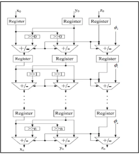
realized by only additions and shifts; therefore, CORDIC algorithm does not require dedicated multipliers. CORDIC algorithm is often realized by pipeline structures, leading to high processing speed. Figure 2shows the basic structure of the pipelined CORDIC unit.
As shown in Eq. 1, the key operation of FFT is x(n). ( = / ) . This is equivalent to “Rotate
[image:2.595.316.559.220.493.2]x(n) by angle 2 / ” operation which can be realized easily by the CORDIC algorithm. Without any complex multiplications, CORDIC-based butterfly can be fast. An FFT processor needs to store the twiddle factors in memory. CORDIC-based FFT doesn’t have twiddle factors but needs a memory bank to store the rotation angles. For radix-2, N-point, m-bit FFT, mN/2 bits memory needed to store N/2 angles [5]. In the next section, a new CORDIC FFT design is presented where CORDIC uses only two angles for rotation.
Figure 1. Rotate Vector ( , ) to ( , )
III. PROPOSEDCORDICBASEDFFT
In FFT we need to find cosine and sine of angles which lies in the range 00 to 1800. The conventional CORDIC
algorithms are used to handle rotations only in the range of angles [-99°,99°]. Moreover, they are serial in nature and require a ROM to store the lookup table and hardware-expensive barrel shifters. So we go for a reduced hardware CORDIC. Our objective is to reduce the number of barrel shifters compared to conventional CORDIC. This, along with the use of small size multiplexers, is expected to result in considerable savings in FPGA resources (in comparison to conventional CORDIC). This is designed for rotation mode. The key idea in this is representing all the angles in
Figure 2. Pipelined CORDIC unit
The range of [0o,180°] using combinations of two
signed elementary angles, tan-1 (1) that is 45o and tan-1 (2-3)
that is 7.12o . In other words, angle Z ε [0o,180°] is
represented by k0 and k1, where k0 and k1 are two integers which depend on the value of Z. Instead of storing rotation angles we only need to store values of k0 and k1. The angle tan-1 (1) is rotated k0 times and the angle tan-1 (2-3) is rotated
k1 times to achieve te desired angle. The elementary angles are chosen as tan-1 (1) and tan-1 (2-3) because corresponding
rotations provide architecture for 16 point FFT butterfly with merely shifters and adder and subtractors.
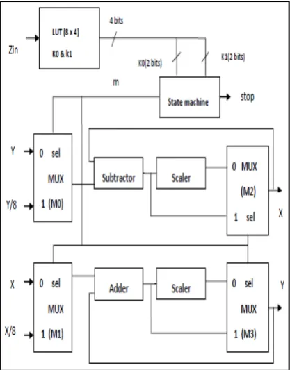
The architecture for proposed CORDIC is shown in Figure 3. The state machine runs k0 + k1 times. It has two outputs: m and stop-bit. One-bit output m is set to 0 for first k0 times and set to 1 for next k1 times. The angle for rotation is tan-1(1), when m is 0 while it is tan−1(2-3), when
[image:2.595.63.271.595.758.2]correction if the rotation is by tan−1(1). The required
correction of S = 0.707 is implemented by a shifted-adder and subtractor.
The multiplexer requirement is brought down to a few 2 to 1 multiplexers as compared to 2, 8 to 1 multiplexers for same accuracy in conventional CORDIC. In conventional CORDIC, 2 pairs of adder/subtractor is used where as in proposed architecture one adder and subtractor is used. The quantities in ROM are stored in sign-magnitude format to save two’s complement logic. For FFT, the values stored in ROM are the rotation values corresponding to angles 0, 22.5o, 45o, 67.5o, 90o, 112.5o,135o, 157.5o, 180o . The
following table shows rotation values corresponding to the above given angles for FFT.
Table 1. Value for k0 and k1 for angles used in FFT
Figure 4 shows the architecture for a reduced hardware CORDIC based FFT Butterfly. In conventional CORDIC we are supposed to give the input angles. But in this proposed architecture we only need to give the address of memory location where the values of k0 and k1 are stored. For example suppose our angle is 45°, the twiddle factor is given
by so our input to CORDIC is 2 instead of
angle 45o. In conventional CORDIC, for angles greater than
[image:3.595.322.554.54.409.2]90, set of iterations have to be repeated 2 times, but in this proposed CORDIC , we are able to rotate up to 180 with single set of iteration.
Figure 3. Proposed Reduced Hardware CORDIC
Figure 4. FFT Butterfly using Reduced Hardware CORDIC
IV. EXPERIMENTALRESULTS
The proposed designs for radix-2 FFT algorithms have been realized by Verilog-HDL and simulated and synthesis using Xilinx ISE 14.1. Synthesis results shown in Table 2 confirm that the proposed design can reduce the total memory used and dynamic power for FFT processors without any tangible increase in the number of logic elements used when compared against the conventional CORDIC implementation (i.e., angles are stored in memory). It was shown that more than 50% of the total memory used is reduced. Furthermore, dynamic power consumption is reduced (up to 30%) with no delay penalties.
Table 2. FFT processor based on Reduced Hardware CORDIC with FFT processor based on Conventional CORDIC
Compared Features
FFT Processor based on
Proposed Reduced Hardware CORDIC
Conventional CORDIC
Dynamic Power Total onchip power Delay
Maximum Frequency Total Memory used
0.412W 1.143W 5.512ns 181.427MHz
444996Kb
0.642W 1.379W 48.831ns 20.479MHz 1203024Kb
V. CONCLUSIONANDFUTURESCOPE
CORDIC is a powerful algorithm, and a popular algorithm of choice when it comes to various Digital Signal Processing applications. Implementation of a CORDIC-based processor on FPGA gives us a powerful mechanism of implementing complex computations on a platform that Angles Value for K0 Value for
K1 0
22.5 45 67.5
90 112.5
135 157.5
0 0 1 1 2 2 3 3
[image:3.595.38.247.478.745.2]provides a lot of resources and flexibility at a relatively lesser cost. Further, since the algorithm is simple and efficient, the design and VLSI implementation of CORDIC based processor is easily achievable. CORDC is further modified to reduce memory used and dynamic power and using that FFT is implemented. FFT designed using modified CORDIC is compared with FFT designed using conventional CORDIC. . It is seen that total memory used and power of FFT processor based on Reduced Hardware CORDIC is less compared to FFT processor based on conventional CORDIC. Operation frequency of modified architecture is also increased.
Although this project primarily deals with the design of 16-point FFT using modified CORDIC algorithm, the concept and the architecture can be extended to calculate the higher order FFTs, thus, providing a fast, low-cost implementation of processors for Image Processing and other Digital Signal Processing Applications. The performance of this FFT processor based on modified CORDIC algorithm can also be compared with that of a FFT processor designed using distributed arithmetic. Reduced Hardware CORDIC can also be used for implementing other Digital Signal Processing Operations and Image Processing Operations such as DCT.
VI. ACKNOWLEDGEMENT
The work described in this paper is supported by Adv.Dr.P.Krishnadas, Managing Trustee and Dr.P Krishnakumar, CEO & Secretary, Nehru Group of Institutions, Tamil Nadu, Kerala-India. Authors are grateful to Prof. Dr. P.N. Ramachandran, Principal and Dr.N K Shakthivel, Vice Principal, Nehru College of Engineering and Research Centre (NCERC), Pampady, Thiruvilawamala,
Kerala, India, for providing us the opportunity to undertake this project.
VII.REFERENCES
[1] C.Wey, S.Lin, & W.Tang, “Efficient memory-based FFT processors for OFDM applications” In IEEE InternationaL Conf. on Electro-Information Technology, 345–350, 2007 May.
[2] J. Volder, “The CORDIC trigonometric computing technique”, IEEE Transactions on Electronic Computers, 8(8), 330– 334, 1959.
[3] A. M. Despain, “Fourier transform computers using CORDIC iterations”, in IEEE Transactions on Electronic Computers, 23(10), 993–1001, 1974.
[4] C. Lin, & A. Wu, “Mixed-scaling-rotation CORDIC (MSRCORDIC) algorithm and architecture for high-performance vector rotational DSP applications”, in IEEE Transactions on Circuits and Systems I, 52(11), 2385–2396, 2005.
[5] M. Garrid, & J. Grajal, “Efficient memory-less CORDIC for FFT Computation”, In IEEE International Conference on Acoustics, Speech and Signal Processing, 2, 113–116, April 2007.
Short Bio Data for the Authors
MUHSINA A A is student of M.Tech in VLSI DESIGN in Department of Electronics and Communication Engineering at Nehru College of Engineering and Research Centre, Pampady, Thiruvilawamala, Kerala, India, affiliated to University of Calicut. She obtained her B.Tech Degree in APPLIED ELECTRONICS AND INSTRUMENTATION from Jyothi Engineering College, Cheruthuruthy, Thrissur, Kerala, India, affiliated to University of Calicut. Her areas of interests are VLSI DESIGN and INSTRUMENTATION.
SIBY T Y is Assistant Professor in Department of Electronics and Communication Engineering at Nehru College of Engineering and Research Centre, Pampady, Thiruvilawamala, Kerala, India, affiliated to University of Calicut. He obtained his M.Tech in EMBEDDED SYSTEMS from Karunya University, Coimbatore and B.Tech Degree in ELECTRONICS AND COMMUNICATION From Mahathma Gandhi University, Kottayam, Kerala. He is member of ISTE. His areas of interests are EMBEDDED SYSTEMS and NETWORK ANALYSIS.
Parameshachari B D working as a Associate Professor and Department Coordinator in the Department of Electronics and Communication Engineering at Nehru College of Engineering and Research Centre, Pampady, Thiruvilawamala, Kerala, India, affiliated to University of Calicut. Worked as a Senior Lecturer and inchage HOD in the Department of Electronics and Communication Engineering at JSS Academy of Technical Education, Mauritius. He worked at JSSATE, Mauritius for Three years and also worked as a Lecturer at Kalpatharu Institute of Technology, Tiptur for Seven years. He obtained his B.E in Electronics and Communication Engineering from Kalpatharu Institute of Technology, Tiptur and M. Tech in Digital communication Engineering from B M S college of Engineering, Bangalore, affiliated to Visveswaraiah Technological University, Belgaum. He is pursuing his Ph.D in Electronics and Communication Engineering at Jain University, Bangalore, Karnataka, India under the guidance of Dr. K M Sunjiv Soyjaudah, Professor, University of Mauritius, Reduit, Republic of Mauritius and Co-guidance of Dr. Sumithra Devi K A, Professor and Director, Department of MCA, R V College of Engineering, Bangalore. Parameshachari area of interest and research include image processing, cryptography and Communication. He has published several Research papers in international Journals/conferences. He is a Member of ISTE, IETE, IACSIT, IAEST, IAENG and AIRCC.
Institution of Engineers,India. and M.Tech in VLSI Design from Amrita Viswa Vidyapeetham,Amritapuri Campus.
Divakara Murthy H S has multi faceted experience in Research, Industry and Academic fields, He is working as a Dean and HOD in the Department of Electronics and Communication Engineering at Nehru College of Engineering and Research Centre, Pampady, Thiruvilawamala, Kerala, India, affiliated to University of Calicut and also served as a Principal at JSS Academy of Technical Education, Mauritius for two years. Involved in Administrative & Academic activities in development of infrastructure facilities marketing, mounting new courses and strategic planning. He worked at RGV telecom Ltd Bangalore as Deputy Vice president,for providing optical
communication for Indian Railways for nealy two years and also worked nearly 27 years in Telecom in Industry at senior level in various capacities in Telecom Projects and Planning, Production and Marketing. During my intial career involved in Design and development of Instrumentation at NAL Bangalore. He obtained his B.E in Electronics and Communication Engineering from Siddaganga Institute of Technology, Tumkur from University of Mysore and MSc(Engg)in communication system from PSG Institute of technology, Coimbatore , from University of Madras. Divakara Murthy area of interest and research include Micro and Pico Satellite communication, Optical Communication and Wireless communication, GSM and WiMAX technology. He is a Member of ISTE, IETE.