Miniaturized Gysel Power Dividers Using Lumped-Element
Components
Ryo Ueda* and Hitoshi Hayashi
Abstract—This letter presents miniaturized Gysel power dividers using lumped-element components. The characteristic impedances of all the equivalent transmission lines in these dividers are fixed to the same values based on even and odd mode analysis, thus simplifying the design procedure and miniaturizing the Gysel power dividers. The ideal divider designed at a frequency of 590 MHz exhibits power splits of −3.2±0.2 dB and return losses of greater than 15 dB for the frequency range of 460 to 650 MHz. Furthermore, isolation between output ports is greater than 15 dB for the frequency range of 500 to 680 MHz. The fabricated miniaturized Gysel power divider achieves broadband characteristics and is very compact, occupying only about 15% of the area of a conventional Gysel power divider.
1. INTRODUCTION
Power dividers play an important role in many wireless communication circuits. Because of the high isolation between output ports, they are used in many devices, including power amplifiers, vector modulators, mixers, phased array antennas, and linearizers. According to their operating power, power dividers can be classified into two groups: low-power dividers, such as the Wilkinson power divider [1], and high-power dividers, such as the Gysel power divider [2]. The Gysel power divider has recently attracted increased attention because of advantages such as its high power handing capabilities; in this aspect, it outperforms the Wilkinson power divider. However, the conventional Gysel power divider typically consists of six 90◦ transmission lines with a design frequency of f0, requiring the divider to have a large area. The reduction method depends on the equivalent circuit of these transmission lines [3]. Using composite right- and left-handed transmission lines [4] reduced the size of the Gysel power divider by 81.8%, and the 15 dB bandwidth isolation was approximately 27.5%. Furthermore, Gysel power divider using equivalent lumped-element components [5] was smaller than that using composite right-and left-hright-anded transmission lines, right-and the 15 dB bright-andwidth isolation was approximately 30%.
This letter describes miniaturized lumped-element Gysel power dividers constructed with a minimal number of lumped elements. Miniaturized lumped-element power dividers and rat-race (or ring) hybrids which utilizes the elimination of inductors and capacitors and unequal power-divider design which utilizes the elimination of an open stub and a short stub were presented [6–10]. However, to the best our knowledge, there is no report about Gysel power dividers which utilizes the elimination of inductors and capacitors positively, while setting the characteristic impedances of all the equivalent transmission lines the same values, to simplify the design procedure and for miniaturization of the Gysel power dividers with low insertion loss.
2. DESIGN AND THEORETICAL ANALYSIS
The configuration of a conventional Gysel power divider is shown in Fig. 1. It consists of six 90◦ transmission lines with a design frequency off0and two isolation resistors. Its characteristic impedances,
Received 18 August 2017, Accepted 29 September 2017, Scheduled 10 October 2017 * Corresponding author: Ryo Ueda ([email protected]).
Port 1 Port 2
Port 3
Z1
,
θ1 Z1
,
θ 1
Z2,θ2 Z2,θ 2
Z3
,
θ3
Z3
,
θ3 R
R
Figure 1. Configuration of Gysel power divider.
electrical lengths, and resistance are Z1 =
√
2Z0, Z2 =Z0, andZ3 =Z0/
√
2;θ1 =θ2 =θ3 = 90◦; and
R = Z0, respectively. Here, Z0 is the reference characteristic impedance. The area it occupies is approximately λ/2×λ/4, where λ is the wavelength on the substrate at the design frequency. Thus, we analyze the Gysel power divider with the electrical lengths of ±90◦ based on even- and odd-mode analysis [11].
2.1. Even-Mode Analysis
Even-mode circuit model of the Gysel power divider is shown in Fig. 2(a). Admittance Yin1 can be written as
Yin1 =
jZ1
2 sinθ2+
1
R+j
1
Z3 tanθ3
cosθ2
cosθ2−ZZ2 3
tanθ3sinθ2+jZR2 sinθ2
. (1)
BecauseYin1 becomes zero at electrical lengths of θ2=θ3 =±90◦ orθ2 =−θ3=±90◦, the circuit seen from this point can be regarded as an open circuit. Moreover, it is interesting to see that the impedances
Z2, Z3, and resistance R do not contribute to the value of the impedance Yin1 for θ2 = θ3 = ±90◦ or
θ2 =−θ3 =±90◦. Therefore, the circuit shown in Fig. 2(a) can be reduced to the network shown in Fig. 2(b). For the impedance to match at ports 1 and 2, the following condition must be fulfilled:
2Z0 =Z1Z0
+jZ1tanθ1
Z1+jZ0tanθ1.
(2)
2Z0 Z0
Z1,θ1
Port 1 Port 2 2Z0 Z0
Z1,θ1
Port 1 Port 2
Z2
,
θ2
Z3
,
θ3 R
Yin1
(a) (b)
Settingθ1 =±90 at the center frequency yields
Z1 =
√
2Z0. (3)
2.2. Odd-Mode Analysis
Odd-mode circuit model of the Gysel power divider is shown in Fig. 3(a). Admittances Yin2 and Yin3 can be written as
Yin2 =−j cotθ1
Z1 , Yin3
=−jcotθ3
Z3 .
(4)
Because Yin2 and Yin3 become zero at electrical lengths of θ1 = θ3 = ±90◦ or θ1 = −θ3 =±90◦, the circuit shown in Fig. 3(a) can be reduced to the network shown in Fig. 3(b). For impedance matching at port 2, the following condition must be fulfilled:
Z0 =Z2R
+jZ2tanθ2
Z2+jRtanθ2
. (5)
Subsequently choosing θ2=±90◦ at the center frequency yields
Z2 =
RZ0. (6)
Z0
Z0
Z1,θ1
Port 2
Port 2 Z2
,
θ2
R
Z3
,
θ3
Z2,θ2
R
Yin3
Yin2
(a) (b)
Figure 3. Circuit of power divider shown in Fig. 1 under odd-mode excitation.
Thus, the parameter of the proposed Gysel power divider should satisfy Equation (3) and Equation (6). These equations demonstrate that the characteristic impedance Z3 can be selected arbitrarily. Thus, we assume that the characteristic impedances of all the equivalent transmission lines are fixed to the same values (Z3 =
√
2Z0 and R = 2Z0). Typical Gysel power divider sets Z3 to
Z0/
√
2 and R to Z0, respectively, while the proposed Gysel power divider sets Z3 to
√
2Z0 and R to 2Z0. To the best of our knowledge, Gysel power divider which sets the same characteristic impedances of all the transmission-line section has not been reported yet.
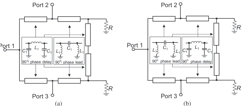
Figure 4 shows the examples of element Gysel power dividers incorporating a lumped-element equivalent. π-network. In these circuits, capacitors with capacitances of C1 = 2√2πf1
0Z0 and
inductors with inductances of L1√Z20
πf0 are used.
Because adjacent inductors and capacitors in the dividers shown in Fig. 4 form parallel resonant circuits whose input impedances are infinite at the center frequency, the elimination of the inductors and capacitors, as shown in Fig. 5, does not affect the electrical distribution and coupling characteristics at the center frequency. Furthermore, the proposed topology does not obey the low-pass or high-pass characteristics. This contributes to the achievement of the broadband characteristics.
L1 C1 L1
Port 2
Port 3 Port 1
R
R
C1
C1
L1
90phase delay 90phase lead
Port 2
Port 3 Port 1
R
R
L1 L1
C1
90 phase lead
C1
C1
L1
90 phase delay
o o o o
(a) (b)
Figure 4. Examples of lumped-element Gysel power dividers using equivalent π-network.
Port 2
Port 1
2C1
Port 3
L1
L1 2C1
C1
L1
C1
L1 R
R
Port 2
Port 1
Port 3
R
R
L1/2 C1
C1 L1
L1C1
C1 L1/2
(a) (b)
Figure 5. Novel configuration of proposed Gysel power dividers using lumped-element components.
3. SIMULATION AND EXPERIMENTAL RESULTS FOR THE PROPOSED GYSEL POWER DIVIDERS
The validity of the proposed circuit configuration was confirmed by simulating the frequency characteristics of the proposed Gysel power dividers using Microwave Office and ADS. We focus on the 470–790 MHz UHF band, which is used predominantly for TV broadcasting in Europe [13]. We assumed that the design frequency f0 was 590 MHz, the reference characteristic impedance Z0 was 50 Ω, the capacitance of capacitor C1 was 3.81 pF, and the inductance of inductor L1 was 19.08 nH.
Figure 6 shows the simulation results for the proposed miniaturized Gysel power dividers shown in Fig. 5. These simulation results were obtained using ideal loss-less lumped elements. As shown in Fig. 6(a), the ideal divider exhibits power splits of−3.2±0.2 dB and return losses of greater than 15 dB for the frequency range of 460 to 650 MHz. Furthermore, isolation between output ports is greater than 15 dB for the frequency range of 500 to 680 MHz. Furthermore, as shown in Fig. 6(b), the ideal divider exhibits power splits of−3.2±0.2 dB and return losses of greater than 15 dB for the frequency range of 540 to 750 MHz. Furthermore, isolation between output ports is greater than 15 dB for the frequency range of 520 to 700 MHz. The simulation results indicate that good isolation and matching are achieved in the passband.
-11 -9 -7 -5 -3
-20 -15 -10 -5 0
0.3 0.4 0.5 0.6 0.7 0.8
Frequency [GHz] S11,
S22, S32 [dB]
S21 [dB]
-11 -9 -7 -5 -3
-20 -15 -10 -5 0
0.3 0.4 0.5 0.6 0.7 0.8
Frequency [GHz] S11,
S22, S32 [dB]
S21 [dB]
(a) (b)
Figure 6. Simulation results for proposed miniaturized Gysel power dividers shown in (a) Fig. 5(a) and (b) Fig. 5(b).
Figure 7. Photograph of fabricated miniaturized Gysel power divider shown in Fig. 5(a).
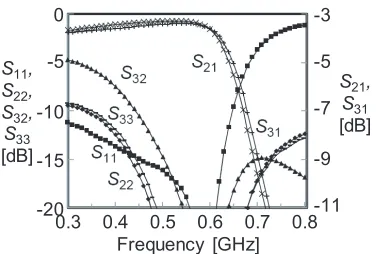
between 0.012 and 0.014, respectively. The chip capacitors, chip inductors, and chip resistors used in the circuit were hand-soldered. The chip capacitors with 1005 size and chip inductors with 1608 size were from Murata Manufacturing Company Ltd. Q value of the chip inductors is 80.65 at frequency 590 MHz.
In this work, we selected a rated voltage of 50 Vdc for the chip capacitors and chip inductors. Furthermore, a rated current max of 1400 mA for the chip inductors (Namely, a maximum handling power is 70 W.) and a maximum working voltage of 75 V and a maximum handling power of 0.1 W for the chip resistors. However, we can select larger lumped elements or can use external resistors if we need larger power-handling capability.
-11 -9 -7 -5 -3
-20 -15 -10 -5 0
0.3 0.4 0.5 0.6 0.7 0.8 Frequency [GHz]
S11,
S22,
S32,
S33
[dB]
S21,
S31
[dB]
Figure 8. Measured results for the fabricated miniaturized Gysel power divider shown in Fig. 7.
Table 1. Performance comparison of proposed and previously reported Gysel power dividers.
Type Size [λ×λ]
15 dB bandwidth of isolation
Power ratio
Design frequency
[GHz]
εr/hof substrate
Proposed Gysel
power divider 0.17×0.11 30% −3 dB (equal) 0.59 4.2/1.6 mm
[4] 0.19×0.12 27.5% −3 dB (equal) 0.9 3.5/0.508 mm
[15] 0.5×0.25 30% arbitrary 2 2.65/0.8 mm
[16] 0.83×0.58 62% −3 dB (equal) 1.5 10.2/1.27 mm
4. CONCLUSION
This letter proposes miniaturized lumped-element Gysel power dividers using lumped-element components. The fabricated power divider achieved about 15% of the area of a conventional Gysel power divider, a bandwidth of about 30% with better than 15 dB isolation, and a bandwidth of about 27% with better than 15 dB return losses. The proposed design is very simple yet is still able to achieve both miniaturization and sufficient broadband characteristics with low insertion loss.
ACKNOWLEDGMENT
The results are based on the outcome of contract research for SCOPE (Strategic Information and Communications R&D Promotion Programme). This work was supported in part by the VLSI Design and Education Center (VDEC) at the University of Tokyo in collaboration with Keysight Technologies Japan, Ltd.
REFERENCES
1. Wilkinson, E. J., “An N-way hybrid power divider,” IRE Trans. Microw. Theory Techn., Vol. 8, No. 1, 116–118, Jan. 1960.
2. Gysel, U. H., “A new N-way power divider/combiner suitable for high-power application,” IEEE
MTT-S Int. Microw. Symp. Dig., 116–118, May 1975.
3. Ahn, H. R. and B. Kim, “Small wideband coupled-line ring hybrids with no restriction on coupling power,”IEEE Trans. Microw. Theory Techn., Vol. 57, No. 7, 1806–1817, Jul. 2009.
5. Tang, B., H. Hayashi, and R. Ueda, “Reduced-size gysel power dividers using lumped-element components,” Microw. Opt. Technol. Lett., Vol. 58, No. 10, 2341–2344, Oct. 2016.
6. Hayashi, H., T. Nakagawa, and K. Araki, “Power distributing/combining circuit,”Japanese Patent
Application Publication No. 2002-064353, 2002.
7. Hayashi, H. and M. Kawashima, “Miniaturized lumped-element power dividers with a filtering function,” IEICE Trans. Electron., Vol. E91-C, No. 11, 1798–1805, Nov. 2008.
8. Hirota, T., A. Minakawa, and M. Muraguchi, “Reduced-size branch-line and rat-race hybrids for uniplanar MMIC’s,”IEEE Trans. Microw. Theory Techn., Vol. 38, No. 3, 270–275, Mar. 1990. 9. Ahn, H.-R., I.-S. Chang, and S.-W. Yun, “Miniaturized 3-dB ring hybrid terminated by arbitrary
impedances,”IEEE Trans. Microw. Theory Techn., Vol. 42, 2216–2221, Dec. 1994.
10. Li, P. W. and K. K. M. Cheng, “A new unequal power-divider design with enhanced insertion loss flatness,”IEEE Microw. Wireless Compon. Lett., Vol. 19, No. 12, 786–788, Dec. 2009.
11. Zhang, H. and Q. Xue, “A novel Gysel power divider with arbitrary power ratio for high-power application,”Proc. IWS 2013, 1–4, Beijing, 2013.
12. Hayati, M., S. A. Malakooti, and A. Abdipour, “A novel design of triple-band Gysel power divider,”
IEEE Trans. Microw. Theory Techn., Vol. 61, No. 10, 3558–3567, Oct. 2013.
13. Oh, S. W., Y. Ma, M. H. Tao, and E. C. Y. Peh, “An overview and comparison of TV White Space regulations worldwide,”Proc. ICFCNA 2014, 1–6, Kuala Lumpur, Malaysia, 2014.
14. Hayashi, H., “Tandem Lange 3-dB 90◦ hybrid implemented on FR4 substrate,” Proc. 2014
NORCHIP, 1–3, Tampere, Finland, 2014.
15. Wu, Y., Y. Liu, and S. Li, “A modified Gysel power divider of arbitrary powerratio and real terminated impedances,” IEEE Microw. Wireless Compon. Lett., Vol. 21, No. 11, 601–603, Nov. 2011.