Volume 2008, Article ID 863629,17pages doi:10.1155/2008/863629
Research Article
Code Tracking Algorithms for Mitigating Multipath Effects in
Fading Channels for Satellite-Based Positioning
Mohammad Zahidul H. Bhuiyan, Elena Simona Lohan, and Markku Renfors
Institute of Communications Engineering, Tampere University of Technology, P.O. Box 553, 33101 Tampere, Finland
Correspondence should be addressed to Elena Simona Lohan,[email protected]
Received 28 February 2007; Accepted 30 September 2007
Recommended by Richard J. Barton
The ever-increasing public interest in location and positioning services has originated a demand for higher performance global navigation satellite systems (GNSSs). In order to achieve this incremental performance, the estimation of line-of-sight (LOS) delay with high accuracy is a prerequisite for all GNSSs. The delay lock loops (DLLs) and their enhanced variants (i.e., feedback code tracking loops) are the structures of choice for the commercial GNSS receivers, but their performance in severe multipath scenarios is still rather limited. In addition, the new satellite positioning system proposals specify the use of a new modulation, the binary offset carrier (BOC) modulation, which triggers a new challenge in the code tracking stage. Therefore, in order to meet this emerging challenge and to improve the accuracy of the delay estimation in severe multipath scenarios, this paper analyzes feedback as well as feedforward code tracking algorithms and proposes the peak tracking (PT) methods, which are combinations of both feedback and feedforward structures and utilize the inherent advantages of both structures. We propose and analyze here two variants of PT algorithm: PT with second-order differentiation (Diff2), and PT with Teager Kaiser (TK) operator, which will be denoted herein as PT(Diff2) and PT(TK), respectively. In addition to the proposal of the PT methods, the authors propose also an improved early-late-slope (IELS) multipath elimination technique which is shown to provide very good mean-time-to-lose-lock (MTLL) performance. An implementation of a noncoherent multipath estimating delay mean-time-to-lose-locked loop (MEDLL) structure is also presented. We also incorporate here an extensive review of the existing feedback and feedforward delay estimation algorithms for direct sequence code division multiple access (DS-CDMA) signals in satellite fading channels, by taking into account the impact of binary phase shift keying (BPSK) as well as the newly proposed BOC modulation, more specifically, sine-BOC(1,1) (SinBOC(1,1)), selected for Galileo open service (OS) signal. The state-of-art algorithms are compared, via simulations, with the proposed algorithms. The main focus in the performance comparison of the algorithms is on the closely spaced multipath scenario, since this situation is the most challenging for estimating LOS component with high accuracy in positioning applications.
Copyright © 2008 Mohammad Zahidul H. Bhuiyan et al. This is an open access article distributed under the Creative Commons Attribution License, which permits unrestricted use, distribution, and reproduction in any medium, provided the original work is properly cited.
1. INTRODUCTION
Today, with the glorious advance in satellite navigation and positioning technology, it is possible to pinpoint the exact location of any user anywhere on the surface of the globe at any time of day or night. Since its launch in the 1970s, the United States (US) Navstar global positioning system (GPS), has become the universal satellite navigation system and reached full operational capability in 1990s [1]. This has created a monopoly, resulting in technical, political, strategic and economic dependence for millions of users [2]. In re-cent years, the rapid improvement and lowered price of com-puting power have allowed the integration of GPS chips into
the new European satellite navigation system Galileo is op-erational, the vast majority of all user receivers sold will be both GPS and Galileo capable [2]. The benefits of receiving signals from both constellations include improved accuracy, reliability, and availability [2].
Galileo signals, as well as GPS signals, are based on direct-sequence code division multiple access (DS-CDMA) tech-nique. Spread spectrum systems are known to offer fre-quency reuse, better multipath diversity, better narrowband interference rejection, and potentially, better capacity com-pared to narrowband techniques [6]. On the other hand, code and frequency synchronization are fundamental pre-requisites for the good performance of the receiver. These two tasks pose several problems in the presence of mobile wireless channels, due to the various adverse effects of the channel, such as the multipath propagation, the possibility of having the line-of-sight (LOS) component obstructed by closely spaced nonline-of-sight (NLOS) components, or even the absence of LOS, and the high level of noise (especially in indoor scenarios). Moreover, the fading statistics of the channel and the possible variations of the oscillator clock limit the coherent integration time at the receiver (i.e., the re-ceiver filters which are used to smooth the various estimates of channel parameters cannot have the bandwidth smaller than the maximum Doppler spread of the channel without introducing significant errors in the estimation process) [7–
11]. The Doppler shift induced by the satellite is also prone to deteriorate the receiver performance, unless correctly es-timated and removed. Moreover, the fading behavior of the channel paths induces a certain Doppler spread, directly re-lated to the terminal velocity. Typical GNSS receivers esti-mate jointly the code phase and the Doppler shifts or spreads via a two-dimensional search in time-frequency plane. The delay-Doppler estimation is usually done in two stages: ac-quisition (or coarse estimation), followed by tracking (or fine estimation). The acquisition and tracking stages will be treated here together, assuming implicitly that the frequency-time search space is reduced, for example, via some assistance data (e.g., Doppler assistance, knowledge of previous delay estimates, etc.). In this situation, the delay estimation prob-lem can be seen as a tracking probprob-lem (i.e., very accurate de-lay estimates are desired) with initial code misalignment of several chips or tens of chips and initial Doppler shift not higher than few tens of Hertz.
One particular situation in multipath propagation is the situation when LOS component is overlapping with one or several closely spaced NLOS components [7, 9–16] mak-ing the delay estimation process more difficult. This closely spaced path scenario is most likely to be encountered in in-door positioning applications or in outin-door urban environ-ments, and is the main focus of our paper.
The main algorithms used for GPS and Galileo code tracking, providing a certain sufficiently small Doppler shift, are based on what is typically called a feedback delay esti-mator and are implemented based on a feedback loop. The most known feedback delay estimators are the delay lock loops (DLLs) or early-minus-late (EML) loops [13,17–21]. The classical EML fails to cope with multipath propagation [6]. Therefore, several enhanced EML-based techniques have
been introduced in order to mitigate the effect of multipaths, especially in closely spaced path scenarios. One class of these enhanced EML techniques is based on the idea of narrowing the spacing between early and late correlators, that is, nar-row EML (nEML) [22–24]. Another class of enhanced EML structures uses a modified reference waveform for the corre-lation at the receiver, that narrows the main lobe of the cross-correlation function, at the expense of deterioration of signal power. Examples belonging to this class are the high resolu-tion correlator (HRC) [24], the strobe correlators [23,25], the pulse aperture correlator (PAC) [26] and the modified correlator reference waveform [23, 27]. One other similar tracking structure is the multiple gate delay (MGD) corre-lator [28–30], where the number of early and late gates and the weighting factors used to combine them in the discrimi-nator are parameters of the model. While coping better with the ambiguities of BOC correlation function, MGD may have poorer performance in multipaths than the narrow EML cor-relator and is very sensitive to the parameters chosen in the discriminator function (i.e., weights and number of correla-tors) [31].
One more feedback code tracking structure is the early-late-slope (ELS) [32] correlator, also known as multipath elimination technique (MET), which is based on two corre-lator pairs at both sides of the correlation function’s central peak with parameterized spacing. Based on these two relator pairs, the slopes of early and late sides of the cor-relation function can be computed and then, the intersec-tion point will be used for pseudorange correcintersec-tion. How-ever, simulation results performed in [23] showed that ELS technique is outperformed by HRC from the point of view of the multipath error envelopes (MEE), for both BPSK and SinBOC(n,n)-modulated signals. ELS is also outperformed by narrow correlator for very closely spaced paths (i.e., be-low 0.1 chip separation) and for paths spaced at about 1/2th of the envelope of the correlation function (i.e., 1 chip spac-ing for BPSK signals and 0.5 chip spacspac-ing for SinBOC(n,n) [23].
The feedback loops typically have a reduced ability to deal with closely spaced path scenarios under realistic as-sumptions (such as the presence of errors in the channel esti-mation process), a relatively slow convergence, and the possi-bility to lose the lock (i.e., they may start to estimate the LOS delay with high estimation error) due to the feedback error propagation. Alternatively, various feedforward approaches have been proposed in the literature and they have been sum-marized in [8]. While improving the delay estimation accu-racy, these approaches are sensitive to the noise-dependent threshold choice.
MEDLL in terms of multipath mitigation capability is pre-sented in [34] for GPS C/A codes. The MEDLL shows bet-ter performance than narrow and wide EML DLLs, but it does not completely eliminate all multipath errors. Espe-cially multipath signals with small relative delays are diffi -cult to eliminate. However, the advantage of MEDLL is that it reduces the influence of multipath signals by estimating both LOS and multipath parameters. However, the perfor-mance analysis of MEDLL has not been much studied for SinBOC(1,1) modulated signals. Moreover, classical MEDLL is based on a maximum-likelihood search, which is compu-tationally extensive. Here, we reduce the search space, by us-ing a noncoherent MEDLL approach and by incorporatus-ing a phase search unit, based on statistical distributions of mul-tipath phases. We will also include MEDLL in our perfor-mance comparison, as a benchmark algorithm.
Another feedforward technique is the slope differential (SD) approach, a recent multipath mitigation scheme based on the slope difference of the prompt correlator output (the correlation is computed between the received signal and the locally generated reference signal). This technique was first proposed in [35]. Advantage of the SD scheme is that it does not require a high speed digital signal processing for the nar-row early-late spacing since it employs only the prompt cor-relator unlike standard DLLs [35]. In [35], it is assumed that the amplitude of the LOS signal is always larger than the am-plitude of the multipath signal, which is a rather limiting as-sumption from the point of view of realistic multipath prop-agation scenarios. Therefore, a slightly modified approach, named as second-order differentiation (Diff2), is proposed in [31]. Unlike SD, Diff2 computes an adaptive threshold based on the estimated noise variance of the channel ob-tained from the feedforward loop in order to estimate the de-lay of the first arriving path. Because of this adaptive thresh-old, Diff2 is able to estimate the first path delay even in mul-tipath profiles where the first path power is less than or equal to the consecutive path powers [31].
The matched filter (MF) concept is another popular feed-forward technique which is extensively studied in [8,36,37]. MF is based on a threshold computation which is determined according to the channel condition provided by the feedfor-ward loop. At first, the noise level is estimated and then a lin-ear threshold is computed based on the noise variance plus some weight factor obtained from the feedforward loop. The choice of the weight factor is dependent on the modulation type. For SinBOC(1,1)-modulated signals, it has to be cho-sen such that the side lobe peaks of the envelope of the cor-relation function (CF) between the received signal and lo-cally generated reference signal can be compensated. There-fore, the first peak of MF which is above the linear threshold corresponds to the estimated delay of the first path.
Another very promising code tracking algorithm is Teager-Kaiser (TK)-based delay estimation algorithm. The principle and the properties of the TK-based delay estima-tion algorithm are described in detail in [38,39]. TK ap-proach proved to give the best results for WCDMA scenar-ios in the presence of overlapping paths [9,38]. According to [8], the performance of this algorithm is also very promis-ing in closely spaced multipath scenarios for LOS delay
es-timation of SinBOC(1,1)-modulated signal in terms of ac-curacy and complexity. However, the best results performed with TK estimator were obtained with infinite receiver band-width. The presence of bandwidth limiting filter affects ad-versely the performance of TK estimator.
The purpose of our paper is two-fold: first, to propose an improved early-late-slope (IELS) technique, which in-creases the MTLL and dein-creases the RMSE compared with the narrow correlator, and secondly, to introduce two peak-tracking-based techniques with optimized parameters, that provide the best LOS estimation accuracy among the other studied algorithms. Aditionally, the step-by-step implemen-tation of a noncoherent MEDLL with incorporated phase es-timation is given for both SinBOC and BPSK signals. In our improved ELS (IELS) technique, we propose two major up-dates to the basic ELS model. The first update is the adapta-tion of random spacing between the early and the late corre-lator pairs. This is mainly because of the fact that the random spacing between the early and late correlator pairs will gen-erally provide more accuracy in order to draw slopes in the early and late sides of the correlation function as compared to fixed spacing, especially when fading channel model is con-cerned. The second update is the utilization of the feedfor-ward information in order to determine the most appropri-ate peak on which the IELS technique should be applied. The peak tracking (PT) algorithms, as mentioned above, combine the advantages of feedback and feedforward techniques, in such a way that the delay estimation accuracy is increased, while still preserving a good mean time to lose lock (MTLL). We remark that the basic ideas of a peak tracking-like algo-rithm have been introduced by the authors in [40]. However, in [40], the PT was using only the second-order derivative estimates and its parameters were chosen empirically. More-over, the algorithm presented in [40] is valid only for Galileo SinBOC(1,1)-modulated signals, while the work here is valid for both GPS and Galileo signals. We also explain here the choice of all the PT parameters and we introduce also the PT-with-TK algorithm.
Simulation results in multipath fading channels are in-cluded, in order to compare the performance of the pro-posed algorithm with the performance of various feedback and feedforward algorithms (some of them have been already mentioned in this introductory chapter, and the rest of them, which are less known or new, are explained in Sections2and
3). The procedure of PT algorithm is detailed inSection 4. The last two sections are dedicated to the simulation results and conclusions.
2. SIGNAL AND CHANNEL MODEL
In what follows, the continuous-time model is adopted for clarity purpose. The signals(t) transmitted from one satel-lite, with pseudorandom (PRN) code can be written as:
s(t)=Ebpmod(t)⊗c(t), (1)
where Eb is bit energy, pmod(t) is the modulation
(spreading is done with a pseudorandom code of chip inter-valTcand spreading factorSF):
c(t)=
∞
n=−∞ bn
SF
k=1
ck,nδ
t−nTcSF−kTc
. (2)
Aboveδ(·) is the Dirac unit pulse,bnis thenth data bit (for
pilot channels,bn=1,∀n) andck,nis thekth chip (±1
val-ued) corresponding to thenth spread bit.
The modulation waveform for BPSK and SinBOC-modulated signals1can be written as [41]:
pmod(t)=pTB(t)⊗
NB−1
i=0
δt−iTB
, (3)
whereNBis BOC modulation order:NB=1 for BPSK
mod-ulation2 andN
B = 2fsc/ fc where fsc is the subcarrier
fre-quency and fcis the carrier frequency for SinBOC
modula-tion,TB=Tc/NBis the BOC interval, andpTB(t) is the pulse shaping filter (e.g., for unlimited bandwidth,pTB(t) is a rect-angular pulse of widthTBand unit amplitude).
The received signalr(t), after multipath propagation and Doppler shift introduced by the channel is
r(t)=Eb
∞
n=−∞ bn
SF
k=1
ck,n L
l=1
al,nejφl,n
×pmod
t−nTcSF−kTc−τl
e−j2π fDt+η(t), (4)
whereLis the number of channel paths,al,nis thelth path
amplitude duringnth code epoch,φl,nis thelth path phase duringnth code epoch, andτlis thelth path delay (typically
assumed to be slowly varying or constant within the observa-tion interval) andη(t) is a wideband additive noise, incorpo-rating all sources of interferences over the channel. Assuming that the signal is sampled atNssamples per chip (for BPSK)
or per BOC interval (for BOC modulation), then the power spectral density of η(·) can be written as N0/(NsNBSF),
whereN0is the noise power in 1 kHz bandwidth (i.e.,
band-width corresponding to one code epoch).
At the receiver side, the incoming signalr(t) is correlated with a replica (reference signal)sref(t) of the modulated PRN
code. The correlation outputR(·) can be written as:
Rτ,τ,fD
=Er(τ)⊗sref(τ)
=E
SFTc
r(t)sref(τ−t)dt ,
(5)
where the correlation is performed over one spreading length of durationSFTc(this corresponds to 1 millisecond for GPS
and Galileo),E(·) is the expectation operator with respect to
1The formulas for CosBOC modulations can be found in [41] and they are not reproduced here for sake of compactness.
2BPSK can be seen as a particular case of BOC modulation, as shown in [41].
the random variables (e.g., PRN code, channel effects, etc.), and
Sref
t,τ,fD
=pmod(t)⊗c(t)⊗δ
t−τe−j2πfDt, (6)
is the reference modulated PRN code with a code phaseτand Doppler shiftfD.
Since the main focus in this paper is the multipath track-ing, we will assume in what follows that there is only a small residual Doppler error after the acquisition processΔfD = fD− fD. Also, if we assume ideal codes and pilot
channel-based estimation (or data removed before the correlation process), thenE(c(t)⊗c(t))=δ(t). With these assumptions, after several manipulations and by replacing (1) to (4) into (5) we get:
Rτ,τ,fD,n
=Eb L
l=1
al,nejφl,nRmodτ−τl+τFΔfD+η(τ,n), (7)
whereRmod(τ)=pmod(t)⊗pmod(t) is the autocorrelation of
the modulation waveform (including BPSK or BOC modula-tion and pulse shaping and whose detailed expression can be found in [41]), and F(ΔfD) = sinc(πΔfDSFTc)e−jπΔfDSFTc
is a deterioration factor due to small residual Doppler er-rors (and it was obtained via integratinge−j2πΔfDt over one code epoch). The filtered noiseη(τ) power spectral density (PSD)N0depends on the PSD of the modulation waveform,
Gmod(f) via
N0=N0Gmod(f)= N0GBPSK/BOC(f)Pfilter(f)2, (8)
where the BPSK and BOC PSD are given by3[41]:
GBPSK(f)=Tcsinc2
π f Tc
, (9)
and, respectively:
GBOC(f)= 1
Tc
sinπ fTc/NB
sinπ f Tc
π fcosπ fTc/NB
2
, (10)
In (8),Pfilter(f) is the transfer function of the pulse shaping
filter. For example, for infinite bandwidth,Pfilter(f)=1 over
the bandwidth of interest.
In a practical receiver, in order to cope with noise, coher-ent and noncohercoher-ent integration of the correlation function might be used. The output after coherent integration overNc
code symbols is
Rτ,τ,fD
= 1
Nc Nc
n=1
Rτ,τ,fD,n
. (11)
The matched filter (MF) output afterNnc noncoherent
integration blocks become:
JMF
τ,τ,fD
= 1
Nnc
Nnc
Rτ,τ,fD
R∗τ,τ,f
D
. (12)
Under the assumption of zero-mean additive noiseη(·), (12) becomes
JMF
τ,τ,fD
≈Eb L
l=1 L
l1=1
alal1e j(φl−φl
1)Rmodτ−Δτl1
×Rmod
τ−Δτl1F
ΔfD
2
+η(τ)2, (13)
whereal=E(al,n) andφl=E(φl,n) are the average amplitude
and phase values of path lover one code symbol interval,
Δτl=τl−τ, andη(τ) is the filtered and averaged noise (after
coherent and noncoherent integration).
3. CODE TRACKING ALGORITHMS
3.1. Early late slope technique (ELS)
The early-late-slope (ELS) multipath mitigation technique can be easily explained by having a look at the signal’s au-tocorelation function (ACF) [32]. The general idea is to de-termine the slope at both sides of the ACF’s central peak. Once both slopes are known, they can be used to compute a pseudorange correction that can be applied to the measured pseudorange. This multipath mitigation technique has tem-porarily been used in some of NovAtel’s GPS receivers, where it has been called multipath elimination technology (MET).
The principle of forming pseudorange corrections is il-lustrated inFigure 1. Here,R(τ) can be, for example, the co-herent correlation function of (11) or the noncoherent out-putJMF(τ,τ,fD) of (12). It can be noticed that the
autocorre-lation peak is distorted due to the influence of the multipath signal. The slope of the correlation function on the early side of the peak isa1, anda2is the slope of the late side of the
peak. The spacing between the early and late correlators isd. Using the slope information the following error function can be derived to accurately estimate how much the correlators need to be moved so that they are centered on the peak [32]:
T= y1−y2+ (d/2)(a1+a2)
a1−a2 , (14)
where T is the tracking error. This is actually the τ -coordinate of the intersection of the two straight lines (i.e., the slopesa1 anda2).T will equal zero when the two
cor-relators are positioned equidistant on each side of the peak. WhenTis non-zero it can be used to feed back to the hard-ware to keep the early and late correlators centered on the peak.
3.2. Improved early late slope technique (IELS)
In our improved ELS (IELS) technique, there are two major updates to the basic ELS model. The first update is the adap-tation of random spacing between the early correlators (i.e.,
R(τ)
τ
K1 K2
K3 K4
y1 y2 y3
y4 d
a1 a2
T
−τ3−τ1 τ2τ4
Figure1: Computation of a pseudorange correctionTby analyzing
the slopes on both sides of the ACF
the spacing betweenE1 andE2) and also between the two late correlators (i.e., the spacing betweenL1 and L2). The rea-son is quite straightforward. The random spacing between the correlators will generally be more appropriate than fixed spacing to draw correct slopes in both the early and late sides of the correlation function, especially when fading channel model is concerned. The second update is the utilization of the feedforward information in order to determine the most appropriate peak on which the IELS technique should be ap-plied. Unlike BPSK, BOC-modulated signal has side peaks with nonnegligible magnitudes. Therefore, there should be a fair way to get rid of these side peaks not being considered as the central peak. Similar with PT algorithm (that will be ex-plained inSection 3.4), an IELS threshold is computed based on the estimated noise variance provided from the feedfor-ward structure. The chosen IELS peak is the one which is above the threshold level as well as the closest to the previ-ous estimation.
3.3. Multipath estimating delay lock loop (MEDLL) implementation
Multipath estimating delay lock loop (MEDLL) is mainly de-signed to reduce both code and carrier multipath errors by estimating the parameters (i.e., amplitudes, delays, phases) of LOS plus multipath signals [15,33]. The MEDLL of No-vAtel uses several correlators (e.g., 6 to 10) per channel in order to determine accurately the shape of the multipath-corrupted correlation function. Then, a reference correlation function is used in a software module in order to determine the best combination of LOS and NLOS components (i.e., amplitudes, delays, phases and number of multipaths). An important aspect of the MEDLL is an accurate reference cor-relation function which could be constructed by averaging measured correlation functions over a significant amount of total averaging time [33].
(τl) and phase (φl) of each multipath component using
max-imum likelihood criteria. Each estimated multipath correla-tion funccorrela-tion is in turn subtracted from the measured cor-relation function. After the completion of this process, only the estimate of the direct path correlation function is left. Fi-nally, a standard EML DLL is applied to the direct path com-ponent and an optimal estimate of the code tracking error is obtained [34,42]. There are several implementations pos-sible for MEDLL algorithm. Here, we chose a noncoherent MEDLL to make the implementation of the algorithm much faster and comparable with the complexity and the imple-mentation of the other discussed algorithms. The steps used in our MEDLL implementation for BPSK and SinBOC(1,1) signals are summarized below.
(1) Find the maximum peak of R(τ) (where R(τ) = JMF(τ,τ,fD) from (12)) and its corresponding delayτ1,
am-plitudea1and phaseφ1. However, we have to mention that
the phase information is lost due to noncoherent integra-tion, thus we recover it by generating random (uniformly distributed in [0 2π]) phasesφland by choosing that one cor-responding to the minimum mean square error of the resid-ual function R(k)(τ),k being the iteration index (see next
step). In practice,Nrandom = 50 phases proved to give
ac-curate enough results (with no so significant computational burden).
(2) Subtract the contribution of the calculated peak, in order to have a new approximation of the correlation func-tion R(1)(τ) = R(τ)− |a
1Rmod,ideal(t −τ1)ejφ1|2. Here
Rmod, ideal(·) is the reference correlation function for a BPSK
or SinBOC-modulated signal, in the absence of multipath (which can be, e.g., computed only once, according to ideal codes [41], and stored at the receiver). We remark that the choice of phase is not important during the first step (due to the squared absolute value), and, thus the phase estima-tion can be ignored during the first step. Find out the new peak of the residual functionR(1)(·) and its corresponding
delayτ2, the amplitudea2and phaseφ2. Subtract the
contri-bution of the first two peaks fromR(τ) and find a new esti-mate of the first peak, as the peak of the residualR(2)(τ)=
R(τ)− |a1Rmod,ideal(t−τ1)ejφ1+a2Rmod,ideal(t−τ2)ejφ2|2.
The reestimated values of the delay and amplitude of first peak are rewritten inτ1anda1, respectively. For more than
two peaks, once the two first peaks are found, the search for thelth peak is based on the residualR(l)(τ)= R(τ)−
|l−1
m=1amRmod,ideal(t−τm)ejφm|2, l ≥ 3. The procedure is continued iteratively until all desired peaks are estimated (see next steps).
(3) The previous step is repeated until a certain criterion of convergence is met, that is, when residual function is be-low a threshold (e.g., set from 0.4 to 0.5 here) or until the moment when introducing a new delay does not improve the performance (in the sense of root mean square error between the original correlation function and the estimated correla-tion funccorrela-tion).
Ignoring completely the phase information and keeping only the amplitude estimates is also possible for MEDLL im-plementation, in order to decrease the computational
bur-den. However, slight deterioration of performance is no-ticed, as seen in the illustrative MEDLL examples ofFigure 2
(“Old MEDLL” method refers to the situation when the phase information is not taken into account, while the “New MEDLL” method refers to the situation when the phase information is searched for, in a random manner as ex-plained above, with Nrandom = 50). Here, Ns is the
over-sampling factor (a chip interval has 40 samples in this example). By increasing the number of random points Nrandom, the “New MEDLL” would approach the
perfor-mance of coherent MEDLL.
3.4. Peak tracking algorithm
The motivation behind the development of the new PT al-gorithm was to find such an alal-gorithm that fully utilizes the advantages of both feedforward and feedback techniques and improves the fine delay estimation. PT utilizes the adaptive threshold obtained from the feedforward loop in order to de-termine some competitive delays, that is, the delays which are competing as being the actual delay (i.e., the delay of the first arriving path). The adaptive threshold is based on the esti-mated noise variance of the absolute value of the correlation function between the received signal and the locally gener-ated reference signal. At the same time, PT explores the ad-vantage of feedback loop by calculating some weight factors based on the previous estimation in order to take decision about the actual delay. However, the utilization of feedback loop is always a challenge since there is a chance to propagate the delay error to subsequent estimations. Therefore, the de-lay error should remain in tolerable range (e.g., less than or equal to half of the width of main lobe of the envelope of the correlation function) so that the advantage from feed-back loop could be properly utilized.
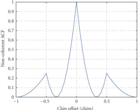
For a SinBOC(1,1)-modulated signal, the width of main lobe of the envelope of an ideal CF between the locally gener-ated reference signal and the received code is about 0.7 chips as shown inFigure 3. Thus, when we deal with SinBOC(1,1) signals, we assume in what follows a maximum allowable de-lay error less than or equal to half of the width of the main lobe (i.e., 0.7/2 =0.35 chips). This means that, if the delay error is higher (in absolute value) than 0.35 chips, the lock is considered to be lost and the acquisition and tracking pro-cesses should be restarted. For BPSK signals, the maximum delay error will be 1 chip (since the width of the main lobe is 2 chips).
The details of the PT algorithm are given inSection 4. Among the feedforward delay tracking algorithms, the matched filter (MF), the second-order differentiation (Diff2), and the Teager-Kaiser (TK) algorithms are described in the next subsections. Diff2 and TK algorithms represent also parts of the building blocks of PT algorithm with Diff2 technique, denoted herein as PT(Diff2) and of PT algorithm with TK technique (PT(TK)).
3.5. MF peak and MF technique
180 170 160 150 140 130 120 110 100 90
Path delays (samples) 0
0.1 0.2 0.3 0.4 0.5 0.6 0.7 0.8 0.9 1
N
o
rm
aliz
ed
co
rr
elation
function
Old MEDLL method (no phase info)
Normalized correlation True path delays Estimated path delays
180 170 160 150 140 130 120 110 100 90
Path delays (samples) 0
0.1 0.2 0.3 0.4 0.5 0.6 0.7 0.8 0.9 1
N
o
rm
aliz
ed
co
rr
elation
function
New MEDLL method, estimated phases
=[1.4361 0.40926 −0.33013] rad
Normalized correlation True path delays Estimated path delays
Figure2: Illustration of MEDLL estimates without (a) and with (b) phase information. A 4-path Nakagami-m fading channel, average path
powers=[0,−1,−2,−3] dB, CNR=30 dB-Hz,Nc=100 ms,Nnc=2,Ns=20. Infinite bandwidth, SinBOC(1,1) signal.
1 0.5
0 −0.5
−1
Chip offset (chips) 0
0.2 0.4 0.6 0.8 1
AC
F
0.7 chips
Figure 3: Ideal envelope of the autocorrelation function of
SinBOC(1,1)-modulated signal.
or equal to a specific threshold (i.e., MFThresh, as explained in Section 3.7.1). The MF peak (MFPeak) is actually the
normal-ized amplitude of local maximum point of the CF squared envelope, which can be obtained using the following equa-tion:
MFPeak= ∀xi{(xi∈MF)∧(xi≥xi−1)
∧(xi≥xi+1)∧(xi≥MFThresh)};
i=2, 3,. . .,lMF−1,
(15)
where ECF here stands for the squared envelope (squared ab-solute value) of the correlation function between the received signal and the locally generated reference signal: ECF =
JMF(τ,τ,fD) (see (12)),∧is the intersection and operator,
andlMF is the length of the set MF. Above, it was assumed
that the samples of ECF are denoted viaxi. In what follows,
we refer to this method as matched filter (MF) method, by analogy with [8].
3.6. Diff 2 peak and Diff 2 techniques
Second-order differentiation (Diff2) peak is defined as any local maximum of the second-order derivative of the ECF, that is greater than or equal to a specific threshold (i.e., Diff2Thresh). The Diff2 peak (Diff2Peak) is also
normal-ized with respect to the maximum value of the secondorder derivative of the ECF. We have:
Diff2Peak= ∀xi
xi∈Diff2
∧xi≥xi−1
∧xi≥xi+ 1
∧xi≥Diff2Thresh
; i=2, 3,. . .,lDiff2−1,
(16)
where Diff2 is the second-order differentiation of JMF(τ,τ,fD) from (12), lDiff2 is the length of the set
Diff2. Since the local maxima of ECF are also seen in the maxima of its second-order derivative, the Diff2 method in-cludes the MF estimates, but it can also detect closely-spaced paths.
3 2 1 0 −1 −2 −3
Delay error (chips) 0
0.1 0.2 0.3 0.4 0.5 0.6 0.7 0.8 0.9 1
N
o
rm
aliz
ed
non-c
o
her
ent
CF
2 path Nakagami-m fading channel model, multipath delay(s): [0 0.75122] chips, CNR: 100 dB-Hz
CF
MF threshold Noise threshold
MF peaks
(a)
3 2 1 0 −1 −2 −3
Delay error (chips) −0.5
0 0.5 1
N
o
rm
aliz
ed
sec
o
nd-or
der
d
i
ff
er
ent
iat
ion
(D
i
ff
2)
2 path Nakagami-m fading channel model, multipath delay(s): [0 0.75122] chips, CNR: 100 dB-Hz
Diff2 Diff2 threshold Noise threshold Diff2 peaks
(b)
Figure4: MF Peaks (a) and Diff2 Peaks (b) illustration. SinBOC(1,1) signal.
3 2 1 0 −1 −2 −3
Delay error (chips) 0
0.1 0.2 0.3 0.4 0.5 0.6 0.7 0.8 0.9 1
N
o
rm
aliz
ed
non-c
o
her
ent
CF
2 path Nakagami-m fading channel model, multipath delay(s): [0 0.75122] chips, CNR: 100 dB-Hz
Figure5: Estimation of noise threshold for the same channel profile as inFigure 4.
the peaks marked in the two subplots correspond to the channel delays and also to the MF and Diff2 peaks (both MF and Diff2 algorithms estimate correctly the channel paths in this example).
3.7. Noise thresholds for MF and Diff 2 algorithms
Noise threshold (NThresh) is obtained based on the noise level
of the ECF. The noise level is estimated by taking the mean
of out-of-peak values of the ECF. The out-of-peak values are all the ECF points which fall outside the rectangular win-dow shown inFigure 5. The rectangular window is chosen such that it contains all side lobe peaks of the ECF, due to BOC modulation, as well as multipath effects (we have to as-sume a maximum delay spread of the channel, but this choice proved not to be so critical). Hence, the width of the rectan-gular window should not be less than 2 chips. In this example case, the width of the rectangular window was 2.4 chips.
3.7.1. MF threshold
MF Threshold (MFThresh) is basically computed from the
esti-mated noise thresholdNThreshand a weight factorWMFusing
the following equation:
MFThresh=max
MFPeak
WMF+NThresh, (17)
where MFPeak andNThresh were defined above and WMF is
defined as follows (the exact choice within these intervals proved not to be critical):
0.1≤WMF≤0.15 for BPSK,
0.3≤WMF≤0.35 for SinBOC(1, 1),
(18)
WMF was chosen optimized empirically (e.g., based on the
levels of the side lobes of ECF of SinBOC(1,1)-modulated signal).Figure 6represents an ideal ECF for SinBOC(1,1)-modulated signal where the side lobe peak have approxima-tively the value 0.25. Therefore,WMF could be chosen
1 0.5
0 −0.5
−1
Chip offset (chips) 0
0.1 0.2 0.3 0.4 0.5 0.6 0.7 0.8 0.9 1
N
o
n-c
o
her
ent
A
C
F
Figure6: Ideal ECF (i.e., squared envelope of the correlation func-tion) of SinBOC(1,1)-modulated PRN Signal.
3.7.2. Diff 2 threshold
Diff2 threshold (Diff2Thresh) is computed from the estimated
noise thresholdNThreshand a weight factorWDvia:
Diff2Thresh=max
Diff2Peak
WD+NThresh, (19)
where Diff2Peak andNThresh were defined above andWD is
defined as follows (based on the second-order derivative val-ues of an ideal ECF):
0.22≤WD≤0.3 for BPSK,
0.37≤WD≤0.5 for SinBOC(1, 1).
(20)
The second-order differentiation of ECF is very sensitive to noise which emphasizes the fact that the weight factorWD
should be chosen higher than the weight factorWMF
cho-sen for MFThresh. That is why the weight factorWDis slightly
greater thanWMF.
3.8. Teager-kaiser (TK) peaks and TK technique
The nonlinear quadratic TK technique was first introduced for measuring the real physical energy of a system [43]. Since its introduction, it has widely been used in various speech processing and image processing applications and, more re-cently, it has also been applied in code division multiple ac-cess (CDMA) applications [38,39,44]. It was found that this nonlinear technique exhibits several attractive features such as simplicity, efficiency and ability to track instantaneously-varying spatial modulation patterns [45]. Teager-Kaiser op-erator is chosen in the context of this paper because it proved to give the best results in delay estimation process when used with other CDMA type of signals, as explained in [38,39,44]. Teager-Kaiser operatorΨTK(·) to a real or complex
continu-ous signalx(t) is given by [39]:
ΨTK(x(t))=x˙(t) ˙x∗(t)−
1 2
¨
x(t)x∗(t) +x(t)¨x∗(t). (21)
For discrete signalsx(n), TK operator is defined as [39]:
ΨTK(x(n))=x(n−1)x∗(n−1)
−1
2
x(n−2)x∗(n) +x(n)x∗(n−2). (22)
TK peak is defined as any local maximum of the Teager-Kaiser operator applied to the ECF, that is greater than or equal to a specific threshold (i.e., TKThresh):
TKPeak= ∀xi
xi∈TK
∧xi≥xi−1
∧xi≥xi+1
∧xi≥TKThresh
; i=2, 3,. . .,lTK−1,
(23)
where TK=ΨTK(JMF(τ,τ,fD)) is the TK operator applied to
ECF andlTKis the length of the set TK.
Above, TK Threshold (TKThresh) is computed similarly
with MF and Diff2 thresholds:
TKThresh=max{TKPeak}WTK+NThresh, (24)
whereWTKweight was obtained from the TK applied to an
ideal ECF and by optimization based on simulations, that is,
0.25≤WD≤0.3 for BPSK,
0.3≤WD≤0.32 for SinBOC (1, 1).
(25)
3.9. Competitive peaks concept
The competitive peaks are to be used in the proposed peak tracking algorithms. A competitive peak (CPeak) can be
ob-tained using the following equations:
CPeak= {(MFPeak)∪(Diff2Peak)}, (26)
CPeak= {(MFPeak)∪(TKPeak)}, (27)
where the symbol∪is used as the union of two sets. This means that we combine the delay estimates given by MF and Diff2, or by MF and TK, and form a set of “competitive” delays, from which the final estimate will be selected.
Since, for GNSS applications, the point of interest is to find the delay of the first arriving path (i.e., the LOS path), therefore, it would be enough to consider only the first few competitive peaks (in their order of arrival). Hence, we as-sume that:
max (L)=5. (28)
Figure 7shows the competitive peaks for the same path profile as in Figures4and5. The competitive peaks are ob-tained using (26). As it can be seen fromFigure 7, for this particular example, there are in total two competitive peaks which compete to be considered as being the actual delay of the LOS path.
3 2 1 0 −1 −2 −3
Delay error (chips) −0.5
0 0.5 1
N
o
rm
aliz
ed
non-c
o
her
ent
CF
,n
or
maliz
ed
D
i
ff
2
2 path Nakagami-m fading channel model, multipath delay(s): [0 0.75122] chips, CNR: 100 dB-Hz
CF Diff2 MF threshold
Diff2 threshold Noise threshold Competitive peaks
Figure7: Competitive peaks of PT(Diff2) algorithm.
An example of peak tracking algorithm with TK tech-nique is shown inFigure 8.Figure 4represents a plot for 2 path Nakagami-m fading channel model withm=0.5. Here, decaying power delay profile (PDP) is used with a multipath separation of about 0.75 chips. Carrier-to-noise ratio (CNR) is considerably high, that is, 100 dB-Hz, in order to empha-size the multipath channel effect. According toFigure 8, the first competitive peak corresponds to the delay of the first arriving path whereas the second competitive peak corre-sponds to the delay of the second arriving path which is about 0.75 chips apart from the first path.
4. DESCRIPTION OF PEAK TRACKING ALGORITHMS
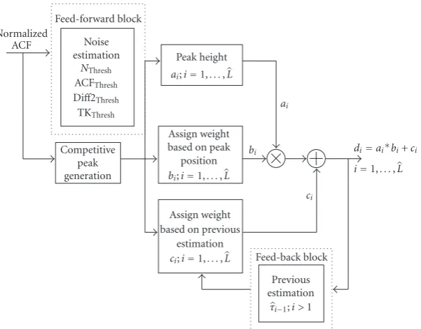
The general architecture of PT algorithms (i.e., PT with Diff2 and PT with TK) is shown inFigure 9. In what follows, the step by step procedure of PT algorithms is presented.
4.1. Step 1: noise estimation
NThresh is estimated according toSection 3.7, which is then
used to determine ACFThresh, Diff2Threshand TKThresh. These
thresholds are then provided as input to the next step.
4.2. Step 2: competitive peak generation
Step 2(a): Look for MF peak(s) in ECF domain using (15). Step 2(b): Look for Diff2 peak(s) in Diff2 domain using
(16) (for PT(Diff2) method) or for TK peak(s) in TK domain using (23) (for PT(TK) method).
Step 2(c): Find competitive peak(s) using (26).
The competitive peak(s) obtained from step 2 are then fed into steps 3(a), 3(b) and 3(c) in order to assign weights in each substep for each particular competi-tive peak.
3 2 1 0 −1 −2 −3
Delay error (chips) 0
0.2 0.4 0.6 0.8 1
N
o
rm
aliz
ed
non-c
o
her
ent
CF
,n
or
maliz
ed
T
K
2 path Nakagami-m fading channel model, multipath delay(s): [0 0.75122] chips, CNR: 100 dB-Hz
CF TK MF threshold
TK threshold Noise threshold Competitive peaks
Figure8: Competitive peaks of PT(TK) algorithm.
4.3. Step 3(a): weight based on peak height
Assign weight(s) (ai),i=1,. . .,L, based on the competitive
peak height(s) using the following equation:
ai=[TMF(τi) +TDiff2/TK(τi)]
2 ; i=1,. . .,L, (29)
whereTMFandTDiff2/Tkare the MF and Diff2/TK correlation
values, respectively, corresponding to a competitive peak:
TMF
τi
=MFτi
, i=1,. . .,L, (30)
TDiff2/TK
τi
=Diff2/TKτi
, i=1,. . .,L. (31)
4.4. Step 3(b): weight based on peak position
Assign weight(s)bi,i= 1,. . .,Lbased on peak positions in
ECF distribution: the first peak is more probable than the second one, the second one is more probable than the third one and so on. This is based on the assumption that typical multipath channel has decreasing power-delay profile. In the simulation, the following weights were used based on peak positions:
[b1b2b3b4b5]=[1 0.8 0.6 0.4 0.2], (32)
wherebi,i=1,. . .,Ldenotes the weight factor forith peak;
that is,b1is the weight for 1st peak,b2is the weight for 2nd
peak, and, so on. It is logical to assign higher weights for the first few competitive peaks as compared to later peaks since the objective is to find the delay of the first path.Figure 10
represents the assignment of weights based on peak position.
4.5. Step 3(c): weight based on previous estimation
Assign weight(s)ci,i=1,. . .,Lbased on the feedback from
Normalized ACF
Feed-forward block Noise estimation
NThresh ACFThresh Diff2Thresh TKThresh Competitive
peak generation
Peak height ai;i=1,. . .,L
Assign weight based on peak
position bi;i=1,. . .,L
Assign weight based on previous
estimation
ci;i=1,. . .,L Feed-back block
Previous estimation
τi−1;i >1
ai
bi
ci
di=ai∗bi+ci
i=1,. . .,L
Figure9: The general architecture of PT algorithms.
5th peak 4th peak
3rd peak 2nd peak
1st peak
Peak position,i
W
eig
ht,
bi 1
0.8
0.6
0.4
0.2
Figure10: Weight assignment (bi,i=1,. . .,L) based on peak po-sition
from the previous estimation, the higher the weight would be for that particular competitive peak. Weight is assigned to each competitive peak according to (33) as follows:
ci=1−(τerr)i, i=1,. . .,L, (33)
where (τerr)i is the delay error of theith competitive peak
with respect to the previous estimation. For example, for a delay difference of 0.1 chips from the previous estimation, the weight factorciwould be 0.9, and for a delay difference
of 0.2 chips, the weight factorciwould be 0.8 and so on.
4.6. Step 4: compute the decision variable
The decision variable (regarding which of the competitive peaks will be declared as LOS peak),di,i=1,. . .,Lis
com-puted according to the following equation:
di=ai∗bi+ci, i=1,. . .,L, (34)
which means that the first two weightsaiandbihave higher
weight than the third weight. This decision variable was also optimized empirically, via simulations.
4.7. Step 5: find estimated delay of the LOS path
The LOS delay can then be obtained via:
τLOS=arg max i=1:L
(di). (35)
Table 1 summarizes the weights assigned in the exam-ple path profile shown inFigure 7for PT(Diff2). Similar re-sults were obtained with PT(TK). In this example case, there are two competitive peaks meaning that we need to assign weights only for those two peaks. In assigning weights for ci,i = 1,. . .,L, PT assumes that there is no initial error
present from the previous estimation. In step 4, the algo-rithm simply computes the decision variabledi,i=1,. . .,L
using (34) for each competitive peak. And, finally, in step 5, PT(Diff2) algorithm selects the peak which has the maxi-mum value for the decision variabledi. In our case, it isd1.
1.2 1 0.8 0.6 0.4 0.2 0
Multipath spacing (chips) −15
−10 −5 0 5 10 15
M
ultipath
er
ro
r
(met
ers)
Butterworth filter, receiver bandwidth: [8 MHz], 2 path channel: [1 0.8], noncoherent correlation
NEML HRC IELS
(a)
1.2 1 0.8 0.6 0.4 0.2 0
Multipath spacing (chips) −15
−10 −5 0 5 10 15
M
ultipath
er
ro
r
(met
ers)
Butterworth filter, receiver bandwidth: [8 MHz], 2 path channel: [1 0.8], noncoherent correlation
MEDLL Diff2 TK
(b)
1.2 1 0.8 0.6 0.4 0.2 0
Multipath spacing (chips) −15
−10 −5 0 5 10 15
M
ultipath
er
ro
r
(met
ers)
Butterworth filter, receiver bandwidth: [8 MHz], 2 path channel: [1 0.8], noncoherent correlation
MF PT(Diff2) PT(TK)
(c)
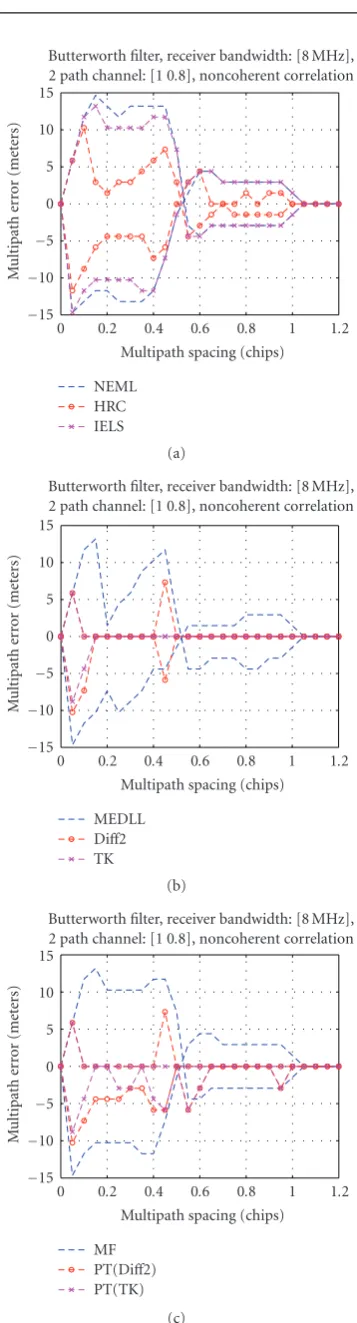
Figure11: Multipath error envelopes (MEEs) for 2 path static chan-nels with path power [1 0.8] for 8 MHz receiver bandwidth.
8 7 6 5 4 3 2 1 0
Time (s) 4.6
4.8 5 5.2 5.4 5.6 5.8
L
O
S
d
ela
y
(c
hips)
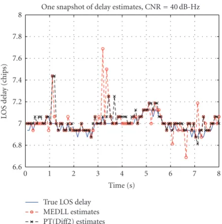
One snapshot of delay estimates, CNR=40 dB-Hz
True LOS delay MEDLL estimates PT(Diff2) estimates
Figure 12: One snapshot of delay estimated by MEDLL and
PT(Diff2) algorithms. SinBOC (1,1) signal,BT=8 MHz.
Table1: Assignment of weights forFigure 7.
1st competitive peak a1 b1 c1 d1
1 1 1 2
2nd competitive peak a2 b2 c2 d2
0.85 0.8 0.25 0.93
5. MEE CURVES
The comparison in terms of multipath error envelopes between the different considered algorithms is shown in
Figure 11for 2-path static channels with linear path ampli-tude values 1 and 0.8. The upper envelope is obtained for in-phase paths, and the lower envelope is obtained for –180 degrees phase shift between the paths. The receiver band-width here was set to 8 MHz and the noncoherent correla-tors were used. We recall the following notations used in the figures’ captions:
(i) nEML=narrow early-minus-late correlator (with 0.1 chip early-late spacing);
(ii) HRC=high resolution correlator (with 0.1 chip early-late spacing and 0.2 chip very early-very early-late chip spac-ing);
(iii) IELS=improved early late slope;
(iv) MEDLL=multipath estimating delay locked loop (im-plemented with phase information);
(v) Diff2=second-order derivative-based algorithm; (vi) TK=Teager-Kaiser-based algorithm;
(vii) MF=matched filter-based algorithm;
(viii) PT(Diff2)=peak tracking with second-order deriva-tive stage;
40 38 36 34 32 30 28 26 24 22 20
CNR 20
25 30 35 40 45 50
RMSE
(met
ers)
Nakagami channel, number of paths: between 2 and 5, Nc=20 ms,Nnc=4,Ns=10, init. del. err.=0 chips
nEML HRC IELS MEDLL Diff2
TK MF PT(Diff2) PT(TK) (a)
40 38 36 34 32 30 28 26 24 22 20
CNR 100
200 300 400 500 600 700
MTLL
(s)
Nakagami channel, number of paths: between 2 and 5, Nc=20 ms,Nnc=4,Ns=10, init. del. err.=0 chips
nEML HRC IELS MEDLL Diff2
TK MF PT(Diff2) PT(TK) (b)
Figure13: RMSE and MTLL for SinBOC(1,1) and infinite bandwidth.
40 38 36 34 32 30 28 26 24 22 20
CNR 20
25 30 35 40 45 50
RMSE
(met
ers)
Nakagami channel, number of paths: between 2 and 5, Nc=20 ms,Nnc=4,Ns=10, init. del. err.=0 chips
nEML HRC IELS MEDLL Diff2
TK MF PT(Diff2) PT(TK) (a)
40 38 36 34 32 30 28 26 24 22 20
CNR 100
200 300 400 500 600 700
MTLL
(s)
Nakagami channel, number of paths: between 2 and 5, Nc=20 ms,Nnc=4,Ns=10, init. del. err.=0 chips
nEML HRC IELS MEDLL Diff2
TK MF PT(Diff2) PT(TK) (b)
FromFigure 11, the best MEE performance is obtained with the feedforward algorithms (TK, Diff2, PT/TK, and PT/Diff2), followed by MEDLL approaches. We also remark that IELS algorithm outperforms the narrow correlator for closely spaced multipath (unlike the results reported in [23]). However, even after the improvements, ELS algorithm is out-performed by HRC method. However, MEEs are rather poor performance criteria since they assume only static 2-path channels and do not take into account the channel changes. More robust performance estimators are those based on root mean square error and mean-time-to-lose-lock values of the delay estimates, as shown inSection 6.
6. SIMULATION RESULTS
Simulation results have been carried in Nakagami-m closely spaced path scenarios for both SinBOC(1,1) and BPSK sig-nals, and for both limited and unlimited bandwidths. The results are described in the next two subsections.
6.1. SinBOC(1,1) case
Simulation results were carried for both infinite bandwidth situation and for some severe bandwidth situation (i.e., 8 MHz double-sided bandwidth limitation). The received fil-ter for finite bandwidth case was a 8-MHz 5th order butfil-ter- butter-worth filter with 0.1 dB passband ripples and 40 dB stopband attenuation. The received signal was sampled atNs=10
sam-ples per BOC interval,Nsbeing the oversampling factor (i.e.,
here we haveNBNs = 20 samples per chip). The channel
paths were assumed to have a Nakagami-m amplitude varia-tion (m=0.5). The channel paths number was assumed to be randomly varying between 2 and 5 paths (uniform distri-bution), and the successive path separation was also a ran-dom variable, distributed between 1/(NsNB) and 0.35 chips
(i.e., closely spaced path scenarios). The channel paths were assumed to obey a decaying power delay profile (PDP), with the decaying factorμ = 0.2/NS/NBOC. 8000 random points
were used in the computation of RMSE and MTLL values. The RMSE was computed only on those delay estimation values which were (in absolute value) less or equal to 0.35 chips (i.e., half of the main lobe of the ECF). The MTLL was computed as the average number of delay estimates whose error (in absolute value) was less than 0.35 chips. The RMSE values are plotted in meters here, by using the relationship RMSE[m] =RMSE[chips]cTc, wherecis the speed of light. It
was also assumed that the initial delay estimate coming from the acquisition stage is accurate to 0 chip delay error, but that the LOS delay is randomly varying in time (with a uniform distribution of±0.05 chips around the previous delay). Thus, the purpose of the delay tracking unit is to keep the lock, that is, to follow these delay variations. A coherent integra-tion time ofNc =20 ms was used, followed by noncoherent
integration onNnc=4 blocks.
A snapshot of estimated LOS delay versus the true LOS delay for two of the considered algorithms is shown in
Figure 12for SinBOC(1,1) signal and 8 MHz receiver band-width.
8 7 6 5 4 3 2 1 0
Time (s) 6.6
6.8 7 7.2 7.4 7.6 7.8 8
L
O
S
d
ela
y
(c
hips)
One snapshot of delay estimates, CNR=40 dB-Hz
True LOS delay MEDLL estimates PT(Diff2) estimates
Figure 15: One snapshot of delay estimated by MEDLL and
PT(Diff2) algorithms. BPSK signal,BT=8 MHz.
Simulation results for SinBOC(1,1) case are shown in Figures13and14, for infinite and finite bandwidth, respec-tively.
As seen in Figures13and14, the best RMSE performance for both SinBOC(1,1) is achieved by MEDLL and PT(Diff2) approaches. However, MEDLL has quite poor MTLL perfor-mance (it tends to lose lock faster), thus the best tradeoff be-tween RMSE and MTLL is achieved, by PT(Diff2) and HRC algorithms. PT(TK) has poorer performance than PT(Diff2) algorithm.
6.2. BPSK case
For BPSK signals, similar parameters as for SinBOC(1,1) sig-nal were used in the simulations. The only differences were a higher oversampling factorNs =16, for an increased
accu-racy (since the number of samples per chip isNsfor BPSK
case, while, for SinBOC(1,1), it was 2Ns) and the
succes-sive path spacing of 1 chip (since the width of the ECF is 2 chips for BPSK). Also, the RMSE values are computed over the delay estimates which are at most half of the main lobe width apart from the true LOS estimate, which corresponds to 1 chip for BPSK case. The statistics were also done for Nrand=8000 random realizations (each random realization
has a length ofNcNncmilliseconds), thus the best MTLL that
can be achieved by our simulations isNrandNcNnc(here, this
corresponds to 640 s).
A snapshot of estimated LOS delay versus the true LOS delay for two of the considered algorithms is shown in
Figure 15 for BPSK signal and 8 MHz receiver bandwidth. RMSE and MTLL values for BPSK case are shown in Figures
40 38 36 34 32 30 28 26 24 22 20
CNR 20
40 60 80 100 120 140 160
RMSE
(met
ers)
Nakagami channel, number of paths: between 2 and 5, Nc=20 ms,Nnc=4,Ns=16, init. del. err.=0 chips
nEML HRC IELS MEDLL Diff2
TK MF PT(Diff2) PT(TK) (a)
40 38 36 34 32 30 28 26 24 22 20
CNR 150
200 250 300 350 400 450 500 550 600 650
MTLL
(s)
Nakagami channel, number of paths: between 2 and 5, Nc=20 ms,Nnc=4,Ns=16, init. del. err.=0 chips
nEML HRC IELS MEDLL Diff2
TK MF PT(Diff2) PT(TK) (b)
Figure16: RMSE and MTLL for BPSK and infinite bandwidth.
Similar conclusions as for SinBOC (1,1) signals are also drawn from Figures 16 and 17, but this time PT(Diff2) outperforms MEDLL also in RMSE values. The differences between infinite bandwidth and limited bandwidth situa-tions are quite small, which means that the algorithms work similarly well in both situations.
40 38 36 34 32 30 28 26 24 22 20
CNR 20
40 60 80 100 120 140 160
RMSE
(met
ers)
Nakagami channel, number of paths: between 2 and 5, Nc=20 ms,Nnc=4,Ns=16, init. del. err.=0 chips
nEML HRC IELS MEDLL Diff2
TK MF PT(Diff2) PT(TK) (a)
40 38 36 34 32 30 28 26 24 22 20
CNR 150
200 250 300 350 400 450 500 550 600 650
MTLL
(s)
Nakagami channel, number of paths: between 2 and 5, Nc=20 ms,Nnc=4,Ns=16, init. del. err.=0 chips
nEML HRC IELS MEDLL Diff2
TK MF PT(Diff2) PT(TK) (b)
Figure17: RMSE and MTLL for BPSK and 8 MHz bandwidth
(But-terworth filter).
7. CONCLUSIONS
promising mean time to lose lock. Among all the consid-ered algorithms, the best tradeoffbetween RMSE and MTLL was achieved via PT(Diff2) algorithm, which decreased con-siderably the delay estimation error at moderate to high CNRs, while still preserving a better MTLL compared with other feedforward tracking approaches. We also presented an improved early-late-slope technique which outperforms the narrow correlator especially in the presence of short delay multipath, where the classical ELS was showing worse results. We have as well presented a reduced complexity implementa-tion of a noncoherent MEDLL, where the phase informaimplementa-tion was searched for via statistical assumptions. Extensive sim-ulation results in both limited and unlimited receiver band-width have been presented, including 9 feedback and feed-forward delay tracking algorithms. We have also shown that at small CNRs (e.g., up to 25 dB-Hz for a coherent integra-tion time of 20 milliseconds), narrow correlator is still the best choice among the considered algorithms. However, its performance is still far from accurate. Better results can be achieved via increasing CNRs (or, alternatively) increasing Nc, with a combined feedback-feedforward approach.
ACKNOWLEDGMENTS
This work was carried out in the project “Advanced Tech-niques for Personal Navigation (ATENA)” funded by the Finnish Funding Agency for Technology and Innovation (Tekes). This work has also been partially supported by the Academy of Finland.
REFERENCES
[1] E. D. Kaplan,Understanding Gps: Principles and Applications, Artech House, Boston, Mass, USA, 1996.
[2] E. Chatre, J. Swann, and D. Ludwig, “Galileo: benefits for lo-cation based services,”Journal of Global Positioning Systems, vol. 2, no. 1, pp. 57–66, 2003.
[3] K. L. Kovach and K. L. Van Dyke, “GPS in ten years,” in Pro-ceedings of the 10th International Technical Meeting of the Satel-lite Division of the Institute of Navigation (ION-GPS ’97), vol. 2, pp. 1251–1259, Kansas City, Mo, USA, September 1997. [4] G. W. Hein, J. Godet, J. L. Issler, J. C. Martin, T. Pratt, and
R. Lucas, “Status of Galileo frequency and signal design,” in
CDROM Proceedings of the International Technical Meeting of the Institute of Navigation (ION-GPS ’02), Portland, Ore, USA, September 2002.
[5] G. W. Hein, M. Irsigler, J. A. A. Rodriguez, and T. Pany, “Per-formance of Galileo L1 signal candidates,” inProceedings of the European Navigation Conference (ENC-GNSS ’04), Rotterdam, The Netherlands, May 2004.
[6] M. K. Simon, J. K. Omura, R. A. Scholtz, and B. K. Levitt,
Spread Spectrum Communication Handbook, McGraw-Hill, New York, NY, USA, 1994.
[7] E. R. J`ativa and J. Vidal, “First arrival detection for position-ing in mobile channels,” inProceedings of the 13th IEEE In-ternational Symposium on Personal, Indoor and Mobile Radio Communications (PIMRC ’02), vol. 4, pp. 1540–1544, Lisbon, Portugal, September 2002.
[8] A. Lakhzouri, E. S. Lohan, R. Hamila, and M. Rentors, “Ex-tended Kalman filter channel estimation for line-of-sight de-tection in WCDMA mobile positioning,”EURASIP Journal on
Applied Signal Processing, vol. 2003, no. 13, pp. 1268–1278, 2003.
[9] E. S. Lohan,Multipath delay estimators for fading channels with applications in CDMA receivers and mobile positioning, Ph.D. thesis, Tampere University of Technology, Tampere, Finland, October 2003.
[10] J. Vidal, M. N´ajar, and R. J´ativa, “High resolution time-of-arrival detection for wireless positioning systems,” in Pro-ceedings of the 56th IEEE Vehicular Technology Conference (VTC ’02), vol. 4, pp. 2283–2287, Vancouver, BC, Canada, September 2002.
[11] N. R. Yousef and A. H. Sayed, “Detection of fading overlap-ping multipath components for mobile-positioning systems,”
IEEE International Conference on Communications, vol. 10, pp. 3102–3106, 2001.
[12] D. D. Colclough and E. L. Titlebaum, “Delay-doppler POCS for specular multipath,” in Proceedings of IEEE Interna-tional Conference on Acoustics, Speech and Signal Processing (ICASSP ’02), vol. 4, pp. 3940–3943, 2002.
[13] G. Fock, J. Baltersee, P. Schulz-Rittich, and H. Meyr, “Channel tracking for rake receivers in closely spaced multipath envi-ronments,”IEEE Journal on Selected Areas in Communications, vol. 19, no. 12, pp. 2420–2431, 2001.
[14] Z. Kosti´c and G. Pavlovi´c, “Resolving subchip-spaced multi-path components in CDMA communication systems,”IEEE Transactions on Vehicular Technology, vol. 48, no. 6, pp. 1803– 1808, 1999.
[15] R. D. J. van Nee, “The multipath estimating delay lock loop,” in
Proceedings of the 2nd IEEE International Symposium on Spread Spectrum Techniques and Applications (ISSTA ’92), pp. 39–42, Yokohama, Japan, November-December 1992.
[16] N. R. Yousef and A. H. Sayed, “A new adaptive estimation al-gorithm for wireless location findingsystems,” inProceedings of the 33rd Asilomar Conference on Signals, Systems, and Com-puters (ACSSC ’99), vol. 1, pp. 491–495, Pacific Grove, Calif, USA, October 1999.
[17] P. Fine and W. Wilson, “Tracking algorithms for GPS offset carrier signals,” inProceedings of the National Technical Meet-ing of the Institute of Navigation (ION-NTM ’99), San Diego, Calif, USA, January 1999.
[18] J. Baltersee, G. Fock, and P. Schulz-Rittich, “Adaptive code-tracking receiver for direct-sequence code division multiple access (CDMA) communications over multipath fading chan-nels and method for signal processing in a Rake receiver,” US Patent Application Publication, US 2001/0014114 A1 (Lucent Technologies), August 2001.
[19] R. Bischoff, R. H¨ab-Umbach, W. Schulz, and G. Heinrichs, “Employment of a multipath receiver structure in a combined GALILEO/UMTS receiver,” in Proceedings of the 55th IEEE Vehicular Technology Conference (VTC ’02), vol. 4, pp. 1844– 1848, Birmingham, Ala, USA, May 2002.
[20] K.-C. Chen and L. D. Davisson, “Analysis of SCCL as a PN-code tracking loop,”IEEE Transactions on Communications, vol. 42, no. 11, pp. 2942–2946, 1994.
[21] M. Laxton, “Analysis and simulation of a new code tracking loop for GPS multipath mitigation,” M.S. thesis, Air Force In-stitute of Technology, Dayton, Ohio, USA, 1996.
[22] A. J. Van Dierendonck, P. Fenton, and T. J. Ford, “Theory and performance of narrow correlator spacing in a GPS receiver,”
Journal of the Institute of Navigation, vol. 39, no. 3, pp. 265– 283, 1992.