Performance & Scalability of a Spatial Database
in a GIS-Web Service Environment
Mark Olthof
Arnhem, 2007
Thesis for a Ir. degree in Computer Science
Performance & Scalability of a Spatial Database
in a GIS-Web Service Environment
Thesis
Project Description
Author
Mark Olthof (S0009202)
Faculty of EEMCS, University of Twente
Chair Databases
Company
LogicaCMG Arnhem
Meander 901, 6801 HA Arnhem
The Netherlands
Department PSAR & GEO-ICT (Nieuwegein)
Project Title SABRE: Optimization of Oracle Spatial database design
Period 1 February 2007 – 18 November 2007
Gradutation Commitee
Maurice van Keulen Harold van Heerde Raynni Jourdain Olaf Lem
(1st supervisor) (2nd supervisor)
I Abstract
LogicaCMG developed SABRE, a spatial business rules server. Its purpose is to process queries for predefined business rules based on a given location.SABRE was rapidly developed as a project for 'master-class' employees. Although a functional demo was created, SABRE remained a simple prototype not ready for commercial purposes. LogicaCMG's goal is to redesign SABRE for commercial purposes, such as for instance tracking and tracing. This project focusses on the optimization of the database part, which will be the foundation of SABRE. If SABRE will be commercially deployed we can expect massive usage, and very high performance requirements. Therefore it's essential to develop SABRE from the ground up in such a way that maximum performance is achieved.
The SABRE architecture consists basically of a Service Provider (SP), Web service (WS) and a Database (DB). The SP requests certain information from the DB through the WS. The aim of this project is to develop a working version of the redesigned SABRE application fit for demonstration purposes. The focus will be on the DB part, therefore the WS will support only one service (e.g. AREA-event). The objective of this assignment is to study the performance and scalability of the DB. The two most important scalability aspects are: how does the DB cope when the amount of requests increases and how does the DB cope when the amount of data increases.
II Preface
This thesis describes my research done for an Ir. Degree in Computer Science. The graduation project took nearly nine months, of which six took place at LogicaCMG Arnhem. The other three months I worked at home, mostly busy writing this thesis. During this project I gained a better understanding of databases and performance and scalability aspects every single day. A lot of my time went into the design and realisation of a prototype. When the prototype had finished, the time came to test my prototype which also took a considerable amount of time. The last part of my project, writing this thesis, took a large amount of time as well, way more than I expected. Although sometimes the outcome of the performance and scalability tests drove me insane because of the unexpected results which caused mind boggling theorizing, I can look back at a interesting nine months.
I would like to thank my LogicaCMG supervisors Raynni Jourdain and Olaf Lem for their devoted support during my stay at LogicaCMG Arnhem. I would especially like to thank Olaf for his insights and the great discussions we have had on the subject matter. I would like to thank my UT supervisors Maurice van Keulen and Harold van Heerde for their hints and tips they gave me which resulted in a more profound research project. Especially during the writing of my thesis their support was crucial. Last but certainly not least I would like to thank my girlfriend, Caroline, for always supporting me during these nine months, especially when I needed it the most.
Mark Olthof
Table of Contents
3.6.1 Division into three separate databases... 28
3.6.2 Data Model... 28
3.7 Chapter Summary... 29
4 SABRE Prototype... 30
4.1 Requirements... 30
4.2 Implementation Prototype...31
4.2.1 Realisation SABRE Data Model ... 31
5.3.1 Technical... 41
6.5.3 Number of transactions and query-load... 48
6.5.4 Influences... 48
A.VI History Sequence Diagram... 89
B Data model - Table descriptions...90
C Create Table Script ...91
D SDO_GEOMETRY... 92
E Relations by Keys...98
F SABRE PACKAGE...99
G SDO_WITHIN DISTANCE... 101
H SDO_NN...103
I MDSYS.SPATIAL_INDEX...104
1 Introduction
This chapter is an introduction to the research done for the project. This chapter contains the motivation for the project, followed by a description of the problem statement. There is a description of the approach taken to complete this project, preceded by the project context, and finally the structure of this thesis is explained.
1.1 Motivation
LogicaCMG's Geo-ICT department at Nieuwegein, a department specialized in geographical information systems and location based services, has had the idea for quite some time to create an application capable of providing location based services. The Geo-ICT department would like to see if they are able to offer their own solution in the growing market of geography related ICT instead of being dependant on other vendors. The idea was born to create a so called spatial business rules server, SABRE in short. The application had to be able to offer location based services, more specific the application had to be able to process location related business rules. To check whether an object is within or nearby a predefined area, based on its given location, is an example of a location related business rule. To stress the relation of business rule and location the word spatial was added, hence the idea of a spatial business rules server was born. The concept of SABRE was to offer its services through means of a web service, for the communication from and to the web service the XML[1.1] standard had to be adopted. The processing of the spatial business rules had to be done by a database, which had to be capable of processing areas and locations. Therefore the processing had to be done by a database specialized in processing areas and location, a spatial database. This lead to a conceptual division into three components, the web service component, the XML component and the spatial database component.
With the concept of SABRE came several requirements. The service had to be offered by a web service, the application needed to be very extensible to be able to support future services and last but not least the application had be deployed in a commercial environment which had some extra requirements. For commercial purposes SABRE had to be able to cope with massive usage and high performance requirements, of which a query-load of about 50 requests per second is a typical estimate. The dataset on which the query is to be performed varies from 300 records up to 3 million records, whereas the query itself consists of retrieving locations, denoted as coordinates, from the database.
The difficulty with creating the spatial business rules server is the high performance requirements of 50 requests per second in combination with the large datasets. Because of the high requirements the application has to be designed to be scalable up to at least 50 requests per second. Because of the large datasets and the processing of areas and locations, the most important aspect of the realisation of SABRE is the spatial database component.
Chapter 1 Introduction 1.2 Problem Description
1.2 Problem Description
The research statement for the thesis states:
“Performance & Scalability of a Spatial Database in a GIS-Web Service Environment.”
As stated in the motivation the most important aspect of the realisation of SABRE is the spatial database component. This leads to the main research question for this project:
“How and with what techniques can a database-design be realised that complies with the performance and scalability requirements of a GIS-Web Service environment?”
To give an answer to the main research question, the question has been split up into several other research questions, because the main research question itself contains several other questions. From answering all the other questions an answer to the main research question can be constructed. Each individual question will be addressed in this thesis, whereas an answer or explanation will be given. From the main research question the following questions are derived:
I. “What is, with respect to this project, performance and scalability?” II. “What is a spatial database?”
III. “What is a GIS?”
IV. “What is a Web Service?”
V. “How can a database-design be realised?”
VI. “How can the scalable database-design be implemented?”
VII. “How can the performance and scalability of the database be measured?”
VIII.“How does a Spatial Database perform in a GIS-Web Service environment in terms of response and transaction times?”
IX. “How does a Spatial Database perform and scale up against increasing user loads and increasing datasets?”
X. “Are there possibilities to significantly improve the performance and scalability by means of database optimizations?”
XI. “If there are significant database optimizations, how well do they influence the performance and scalability of the database?”
XII. “If there are significant database optimizations, can they be used in conjunction or separately, and which is the best (combined) optimization with respect to this project?”
Chapter 1 Introduction 1.3 Project Context
1.3 Project Context
LogicaCMG has already made an attempt to create the spatial business rules server. SABRE was rapidly developed as a project for 'master-class' employees. New employees of LogicaCMG attended a master-class, a form of study to get the new employees up to date with the latest technologies, where they were given the task to convert the SABRE idea into a working implementation of SABRE. Although the employees created a working version of SABRE, it's design did not meet all of its requirements for commercial usage. Because of the promising results of SABRE, people at Nieuwegein decided that SABRE had to be redesigned and built up from scratch again to meet the requirements for commercial usage. Not knowing if a new version of SABRE would be able to meet the necessary requirements they needed some specific research and decided to create a graduation project. This graduation project had to contain the development of a prototype and research on the performance of the prototype. The outcome of the graduation project should give the Geo-ICT department an answer to whether or not the SABRE idea could be used in a commercial environment.
The creation of a complete new SABRE application is far too much work for a single graduation project. Therefore the SABRE project was split up into two smaller projects, a Web Service part and a Database part. The latter one was chosen for this graduation project. Another graduation project is expected, which will focus on the Web Service part, to be realized after this project has successfully finished.
1.4 Approach
LogicaCMG's goal is to re-develop SABRE in a profound manner so it can be used for commercial purposes. LogicaCMG has set two different objectives. The first, to develop a working demo-version of the new SABRE application. Second, measure the performance and scalability of the newly built application. The working demo-version only contains basic functionality but should be designed in such a way that the application is scalable and is able to support future additions. The demo-version can then be used, as the word says, for demonstration purposes, trying to attract customers. Next to having a demo-version LogicaCMG also wants to know if the application can be used for commercial purposes. If the application is to be used in a commercial environment LogicaCMG must be able to say something about its performance and scalability. Therefore LogicaCMG wants to find out how well the application performs in a typical commercial environment and how the application scales up against massive usage.
If it is possible to create a new SABRE application which meets the requirements for commercial usage of about 50 requests per second and is scalable as well, we might see SABRE being used in a commercial environment in the near future.
This research project focusses on the database part of SABRE, the spatial database component to be more specific. The XML component is lightly addressed and beyond the scope of this thesis. The web service component will mainly be addressed in the redesign phase, and is further on mostly considered beyond the scope of the project, as it most likely will be thoroughly investigated in another graduation project. The research project is about the redesign of the SABRE application, whereas a simplified prototype will be implemented based on the new design. The prototype will only contain the bare necessities to accommodate the research and to be a profound realisation of SABRE as well. The new design will include optimizations to improve the performance and scalability of the application. Finally, the performance and scalability of the new design will be evaluated, including the optimizations.
The general approach for the research project is as follows:
✔ Study the original SABRE application, it's design and implementation, to familiarize with the functionality of the application.
Chapter 1 Introduction 1.4 Approach
✔ Study on Database optimization techniques, determine in what degree they influence the design of SABRE. Determine if the optimizations need to be dealt with at the design phase or if they can be realised afterwards.
✔ Redesign the SABRE application in a profound manner, with optimal scalability and performance in mind.
✔ Implement the SABRE prototype.
✔ Set up a test case and determine what methodology can be used to asses the performance and scalability.
✔ Execute the performance and scalability testing, including optimizations, and gather the results.
✔ Analyse the results and draw conclusions from them.
✔ Make recommendations based on the conclusions.
If all steps above are completed the final result is a thesis about the performance and scalability of a spatial database in a GIS-Web Service environment.
1.5 Project Goal
This research project has two distinct goals. The first, the redesign of SABRE, designed to be scalable, and the delivery of a prototype of a working demonstration version based on the new design. Second, investigate the behaviour of SABRE, test and improve, by means of optimizations, the performance and scalability.
1.6 Thesis Structure
2 Related Work
This chapter contains information on related work. It contains a description of the terminology, and related technologies. This chapter provides an answer to the first four research questions:
“What is, with respect to this project, performance and scalability?” “What is a spatial database?”
“What is a GIS?”
“What is a Web Service?”
These terms are explained in this chapter. Amongst other definitions the terms performance and scalability are defined which are very essential for this project.
2.1 GIS
GIS is an abbreviation for Geographical Information System, an information system used for storing, retrieving and analysing geographical information. It is a computer system capable of integrating, storing, editing, analysing, sharing, and displaying geographically-referenced information. Basically, a GIS is a tool that allows users to create interactive searches, analyse the spatial information, edit data, maps, and present the results of all these operations. The application of GIS technology is very widespread, GIS can be used for:
✔ Scientific investigations
✔ Resource management
✔ Asset management
✔ Environmental impact assessment
✔ Urban planning
✔ Cartography
✔ Criminology
✔ History
✔ Sales
✔ Marketing
✔ Logistics
Chapter 2 Related Work 2.1 GIS PostgreSQL. Nowadays Oracle Spatial is used by many Geographical Information Systems, because with the birth of Oracle Spatial companies were able to program their own systems. Before Oracle Spatial the companies were dependant of the GIS vendors, therefore Oracle Spatial is rising in popularity. PostgreSQL is also rising in popularity but lacks the extensive amount of support that Oracle Spatial has. PostgreSQL is becoming rapidly more mature, but is no where near the maturity level of Oracle Spatial.
2.2 DB Techniques
A GIS uses digital information, the generation of the digital information can be done in several ways. The most common way is digitization, where a hard-copy plan or map is converted into a digital medium. There are two methods for storing the digital information inside the database, raster and vector. Raster data consists of rows and columns of cells where each cell contains a value. For example, a cell can contain a value representing a colour, whereas multiple cells together form a picture which can represent a map. Vector data is represented by geometries, points and lines, and or polygons, also called areas. Geometries and polygons represent objects. These objects together can be used to construct, for example a road-map. A GIS can perform spatial analysis on the spatial data, several examples of spatial analysis are:
✔ Data modelling calculations can be very diverse and application specific, most commonly used are graph theory and matrix algebra.
2.3 Benchmarking
Chapter 2 Related Work 2.3 Benchmarking
the performance of a database as well as compare the performance with other benchmarks. There are several industry standard benchmarks available for benchmarking databases. These benchmarks are from the Transaction Processing Performance Council[TPC]and include the following benchmarks:
✔ TPC-App, an application server and Web Services benchmark.
✔ TPC-C, a benchmark which simulates a complete computing environment where a population of users executes transactions against a database.
✔ TPC-E, a benchmark for On-Line Transaction Processing (OLTP[2.1]).
✔ TPC-H, a benchmark for decision support systems.
These benchmarks are industry standard benchmarks, they provide a predefined simulated real-world scenario for databases and base the benchmarks on these simulated scenarios. Therefore the benchmarks do not represent the real performance of the database in its daily basis operation. For the project it is essential to benchmark the performance of the actual SABRE scenario and not a predefined simulated scenario. Therefore using an industry standard benchmark is not an option for this project.
There aren't many professional database benchmark programs available, at this moment, which can benchmark a actual database scenario. One such program is Benchmark Factory from Quest Software[BFQ], it features a high degree of customization. These customizations make it possible to create a tailored benchmark for the SABRE scenario. Therefore the logical choice of program used for benchmarking SABRE is Benchmark Factory.
2.4 Definitions
The research question for the thesis states: “Performance & Scalability of a Spatial Database in a GIS-Web Service Environment.” The sentence contains several words which can have different definitions. For the thesis it's essential to describe the definitions used, to uniformly define a terminology. The following terms need to be defined: performance, scalability, spatial database, GIS and Web Service. The three last terms are merely names for a specific technology whilst the first two are essential terms which need to be defined for the scope of the project.
✔ Spatial Database
○ 'A Spatial Database is a database that is optimized to store and query data related to objects in a defined geometric space, including points, lines and polygons. While typical databases can understand various numeric and character types of data, additional functionality needs to be added for databases to efficiently process spatial data types. These are typically called geometry or feature'.[WKP1]
✔ GIS
○ GIS is an abbreviation for Geographical Information System, an information system used for storing, retrieving and analysing geographical information. See also chapter 2.1.
✔ Web Service
○ 'According to the World Wide Web Consortium[W3C](W3C) a Web Service is a software system
designed to support inter operable Machine to Machine interaction over a network. The W3C Web service definition encompasses many different systems, but in common usage the term refers to clients and servers that communicate using messages (XML) that follow a standard (SOAP[2.2]-standard). Common in both the field and the terminology is the assumption that there
is also a machine readable description of the operations supported by the server, a description (WSDL[2.3])'
Chapter 2 Related Work 2.4 Definitions
✔ Performance
○ In perspective to the project the term performance is related to performance testing. 'In software engineering, performance testing is testing that is performed, to determine how fast some aspect of a system performs under a particular workload. It can also serve to validate and verify other quality attributes of the system, such as scalability and reliability'.[WKP3]
○ In this project performance is measured as: (see chapter 6.3)
■ Transactions per second.
■ Response time in milliseconds.
■ Transaction time in milliseconds.
✔ Scalability
○ In perspective to the project, scalability is defined as the ability of a database to maintain throughput, measured in transactions per second, under an increased load in a graceful manner, whereas load is defined as query load, requests per second, or data set size, number of records inside a data set. For example if the query load increases, more requests per second, or the data set size increases, how does the database scale up against the increasing load in respect to transactions per second. If the load increases we expect to see a decrease in transactions per second. Scalability is about the relation between increase in load and decrease in transactions per second. If the decrease in transactions per second under an increased load is not in a graceful manner, the database does not scale. A database is said to be scalable if when we increase the resources in a system, it results in increased performance in a manner proportional to resources added.
○ The idea behind scalability is that if a database is scalable it is possible to increase the resources to increase performance, in a proportional manner, thereby being able to cope with an increasing load. A database that does not scale has a proportionally low increase in performance while more resources are added.
2.5 Chapter Summary
3 Design SABRE Application
This chapter discusses the redesign of the original SABRE application. It starts with an introduction to the original version and follows with the design and implementation of the new SABRE application. Design choices will be discussed as well as the requirements for SABRE. This chapter addresses the following research question: “How can a database-design be realised?”
The general idea behind SABRE is to be able to provide a service, based on a location. These services have to be customizable in a high degree. Therefore the design is centred around the idea of providing different services. Next to services, SABRE has to operate with locations. This results in a design with a relation between services and locations, each service can contain multiple locations. The idea is to map each service onto several locations, so each service queries only the locations it is mapped onto. As a result SABRE is, simply put, able to provide location based services, its only requirement to operate is the location of an object. For example, SABRE should be able to determine if an object is inside one or more areas. Which specific areas or locations to check against are determined by the service.
3.1 Requirements SABRE
With the redesign of the SABRE application came a lot of requirements. The requirements can be divided into functional and non-functional requirements. The non-functional requirements are the requirements that can be used to judge the operation of a system, rather than the specific behaviour. For SABRE the non-functional requirements consist of:
✔ Performance, SABRE has high performance requirements, it should be able to process at least 30 requests each second. This amount may likely increase to 60 request per second. The values of 30 and 60 are a rough estimate based on LogicaCMG's usage expectations.
✔ Scalability, SABRE needs to be a scalable application. ✔ Security, SABRE must be able to support authentication.
✔ Extensibility, SABRE must be designed in such a way that future Services can be easily added. The Extensibility requirement takes precedence over performance and scalability.
✔ Use of Oracle Spatial for the spatial processing functionality. ✔ Use of a Web service for the deployment of the SABRE services. The functional requirements consist of:
✔ Services, SABRE must be able to offer location based services, referred to as Services. Given a location, denoted as a coordinate, of an object, SABRE must be able to offer Services based on the objects location. This design will only contain one type of Service, the AREA-event Service. The AREA-event Service determines whether or not a given object in inside a predefined area, based on the object's location.
✔ Check Credentials, this process is used to authenticate a user, it provides a means of security. ✔ Check Coordinate, this process checks the given coordinate, defined by X and Y, on whether it is
in or out a predefined area. The process returns IN or OUT.
✔ Create XML, this process gathers the response from SABRE and encapsulates this response in a XML message to return to the Service Provider.
Chapter 3 Design SABRE Application 3.1 Requirements SABRE
✔ Check Sensor, this optional process can modify the Service_ID based on a sensor value. If the value of the sensor is above or below a defined threshold the Service_ID can be modified accordingly. This provides a means to change the locations to be checked, by altering the Service_id another Service is used and thus other locations are checked.
✔ Process Status, this optional process is used to determine if an object is possibly leaving or entering an area, based on the object's previous location.
✔ Process History, this optional process is able to return an object's location history.
✔ Process AREA, this optional process can insert, update or delete an area. Its purpose is to add, update or delete a location (or area) of a specific Service. Because this project only uses the AREA-event Service, so there is no need for AREA processing, this requirement is included in the SABRE architecture but intentionally left out in the SABRE detailed design as it is beyond the scope of this project.
The requirements contain al lot of terms which need some clarification, below is the terminology used shown.
✔ Object
○ An object has always a location. The object itself is not used, only its location.
○ An Object_ID is a number used to uniquely identify an object.
✔ Area
○ An area is determined by a predefined set of coordinates.
✔ Event
○ An event determines the type of service, for example an AREA-event, see chapter 3.5 “SABRE Data Model“ for more information.
✔ Location
○ Every object has a location, the location is determined by its coordinates.
✔ Coordinate
○ A coordinate is for spatial processing, a coordinate is a pair of an X and Y value.
✔ Service_ID
○ A Service_ID is a number to uniquely identify a Service, each Service has its own unique ID.
✔ ACK
○ Acknowledged, meaning accepted or admitted
✔ NACK
○ Not Acknowledged
✔ Status
○ The status of an object, whether it is entering or leaving an area.
✔ History
Chapter 3 Design SABRE Application 3.2 Original version
3.2 Original version
SABRE in its original form was an application capable of some specific tracking and tracing. It was designed and implemented by LogicaCMG and intended as a training exercise for new LogicaCMG employees. Although a functional demo was created of the application showing promising capabilities, it did not meet the performance and scalability requirements for commercial exploitation. Because of the promising results of the prototype LogicaCMG decided that a renewed version of SABRE had to be made. The new version had to be designed in such a way it could cope with the high performance requirements next to being scalable and extensible, so it eventually could be used in a commercial environment.
The original version of SABRE consisted of a database containing locations and area's, and some lines of .NET code to perform the database transactions. It checked if an object was inside its defined area. The checking was done by spatial processing by the database, Oracle Spatial. The idea was to check if a given coordinate, the location of an object, was inside a predefined area, an Oracle Spatial geometry. Because Oracle Spatial performed very well, the redesigned SABRE application had also to be based on Oracle Spatial. Hence the requirement of usage of Oracle Spatial for the new SABRE application.
3.3 SABRE Architecture
The SABRE application can be divided into three different layers, each layer providing its own specific functionality. The idea behind this design is to see each layer as a component of SABRE. So SABRE consists of three different components. These components are the XML-component, the Web Service -component and the Database-component. Figure 3.1 shows a schematic view of SABRE.
The diagram is a top-level view of SABRE, emphasizing the components marked by different colours. The components are described below along with their responsibilities.
XML-component
✔ Interface between the Internet and the Web Service
✔ XML file containing detailed information about available Services
✔ Handles all communication between the Internet and Web Service
✔ Provides security through means of authentication
Web Service-component
✔ A bridge between the Internet and the spatial database
Chapter 3 Design SABRE Application 3.3 SABRE Architecture
✔ Delivers Services to customer and creates and modifies Services
✔ Responsible for all service related tasks
✔ Requires authentication
✔ Shields the database from the internet
Database-component
✔ Handles spatial processing requested by Web Service
✔ Communicates only with Web Service
✔ Handles primarily spatial-queries
By this design the architecture meets the requirements of security, services, use of a web service and use of Oracle Spatial. The remaining requirements of performance, scalability and extensibility are strongly related to the implementation of the data-model of the database and will be discussed in chapter 3.5. Next, the functional requirements will be discussed.
3.3.1 XML Component
The XML-component is the interface between the service provider and the Web Service. The service provider requests Services by sending a XML-encoded message. The Web Service replies through also sending a encoded message, containing the reply. The are two different interfaces for the XML-component, the service provider interface and the Web Service interface.
The Service Provider interface provides the following functionality:
✔ Login to WS
✔ Life cycle:
1. Requests available services
2. Create service (subscribe)
3. Modify service
4. Delete service
5. Start/stop service ✔ Operate service
✔ Supply object location
✔ Retrieve history
✔ Modify area
The Web Service interface provides the following functionality:
✔ Grant or deny access
✔ Supply answer based on object location
✔ Service modification confirmation (ACK/NACK)
Chapter 3 Design SABRE Application 3.3 SABRE Architecture
The XML-file should contain at least the following items. Items marked with * are mandatory.
✔ User name *
✔ Password *
✔ Service ID*
✔ X-coordinate *
✔ Y-coordinate *
✔ Object ID (optional, for history purposes)
✔ Sensor (optional, the sensor may contain more values, array-like)
3.3.2 Web Service Component
The Web Service component will only support one type of service, the AREA-event service. The function of this service is to determine if a given coordinate is inside a predefined area. The service can supply the following answers:
✔ INSIDE [YES]
○ The given coordinate is inside the area
○ BORDER [INSIDE]
■ The given coordinate lies on the border of the area. The border of an area is part of the area itself, thus a coordinate which lies on the border is also within the area.
✔ OUTSIDE [NO]
○ The given coordinate is not inside the area
3.3.3 Database Component
Three different databases can be distinguished for the SABRE application, each with its own specific functionality. The division into three separate databases is based on performance grounds, see chapter 3.6.1. The three databases are:
✔ Spatial Database (SDB)
✔ Non Spatial Database (NSDB)
✔ Web Service Database (WSDB)
Chapter 3 Design SABRE Application 3.3 SABRE Architecture
The interaction consists of the following functionality: ✔ Web Service to SDB
○ Check the given coordinate of an object against the location(s) corresponding to the requested service.
○ Optional functionality:
■ Insert/update/delete an AREA
✔ SDB to Web Service
○ Reply [ACK/NACK] for an AREA modification or [IN/OUT] for a coordinate check.
○ Optional functionality:
■ Supply details on NACK, may contain a reason or description on what caused the NACK.
The requirement of the history functionality is provided by the NSDB. It is responsible for the issue of logging coordinates. The SABRE application should be able to keep track of coordinates supplied by the Service Provider. By means of storing all coordinates of a certain service by Object_ID, the application can supply the Service Provider with some sort of history. How the stored data is used to form a history isn't important right now, as it is beyond the scope of this design. The only thing important is that the coordinates will be logged and stored.
The NSDB consists of the following functionality:
✔ WS to NSDB
○ Request history [Object_ID]
○ Store coordinate [(X,Y),Object_ID]
✔ NSDB to WS
○ Supply object history [Object_ID,(X,Y)1,...,(X,Y)n]
There is also a third Database, the Web Service Database. The WSDB has functions specific for the Web service. The WSDB has the following functionality:
✔ Check supplied credentials, providing a security measurement.
Chapter 3 Design SABRE Application 3.3 SABRE Architecture
✔ Check Sensor, may change the Service_ID to address another Service.
The Web service, WSDB interaction consists of the following functionality:
✔ WS to WSDB
○ Check user name/password to allow or disallow access to the Service.
○ Process Status and determine the state of the object.
○ Check the sensor based on the sensor-value and determine if the Service_ID needs to be changed.
✔ WSDB to WS
○ Reply if the login was successful [Y/N]
○ Return the status of the object [Enter/Leave]
○ Return the Service_ID
3.4 Detailed SABRE Design
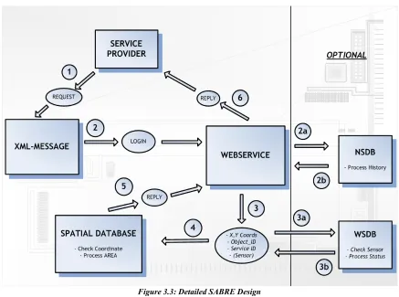
Figure 3.3 shows the design of the SABRE application in more detail.
Chapter 3 Design SABRE Application 3.4 Detailed SABRE Design
contents, between them. The optional parts are separated by the vertical line whereas the database component is split into the three different databases to accommodate the optional parts.
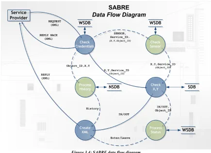
The figure shows the contents of the communication between the components in the ovals between the arrows. The numbering denotes the order in which the flow of data takes place. The optional routes, 2a followed by 2b and 3a followed by 3b, show the optional processes of history, sensor check and status. Figure 3.4 shows the SABRE data flow diagram.
This figure shows the flow of data as seen from the service provider, it shows the possible routes a request can travel. Each single request travels through the data flow diagram where it can take its desired route. The data flow diagram consists of five routes but a single route can be taken only one at a time, the flow is always forwards in the direction of the arrows. The text alongside the arrows represents the contents of the data, the text between parentheses represent the data which is inside the flow but not needed for the process the flow is heading to. The three databases, SDB, NSDB and WSDB are displayed as a data store, a location where data is held temporarily or permanently. The WSDB is addressed three times whereas the other two data stores are only used once. Each circle defines a process, the process takes the input data and creates (transformed) output data. These processes are:
✔ Check Credentials
✔ Check Sensor*
✔ Check X,Y (Coordinates)
✔ Process Status*
Chapter 3 Design SABRE Application 3.4 Detailed SABRE Design
✔ Process History*
✔ Create XML
Note that the processes are directly derived from the functional requirements. The processes marked with * are optional processes, the data flow for these processes is marked by a dashed line in the data flow diagram, whereas the processes itself are marked green instead of blue.
The following sequence diagrams are derived from the data flow diagram. The sequence diagrams show the required components for the (optional) functional requirements of SABRE, as parallel vertical lines, the different processes or objects that live simultaneously and the messages that are exchanged between them, in order of occurrence. There are five different sequence diagrams each representing a different route in the data flow diagram.
✔ Basis sequence diagram, showing the basic function without any optional functionality.
✔ Sensor check sequence diagram, showing basic functionality including the sensor process.
✔ Status sequence diagram, showing basic functionality including the status process.
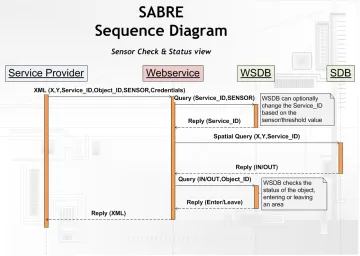
✔ Sensor check & Status sequence diagram, showing basic functionality including the sensor and status process combined.
✔ History sequence diagram, showing basic functionality including the history process.
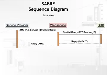
The sequence diagram in figure 3.5 shows the basic operation of SABRE.
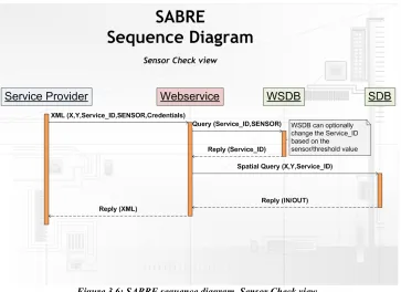
The figure shows the sequence of processing a request. The text alongside the lines represent the data of the request. The vertical orange bars denote the relative time required by the components, displayed in the text-boxes, to process the request. Figure 3.6 shows the sequence diagram including the sensor check process. There is an extra process of addressing the WSDB which may result in a change of Service_ID.
Chapter 3 Design SABRE Application 3.4 Detailed SABRE Design
Figure 3.7 shows the sequence diagram including the status process.
The diagram shows an extra process of addressing the WSDB to determine if the object is entering or leaving Figure 3.6: SABRE sequence diagram, Sensor Check view
Chapter 3 Design SABRE Application 3.4 Detailed SABRE Design
an area. This process takes place after the SDB has been addressed to check the coordinate. Figure 3.8 shows the sequence diagram including the sensor check and status process.
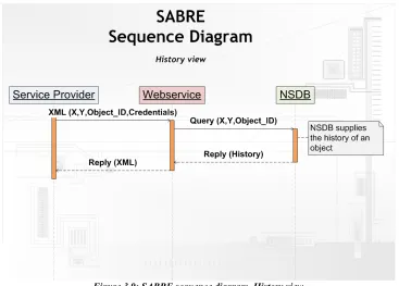
The sequence diagram is a combination of the sensor check diagram and the process status diagram. The sensor check is executed first, followed by the coordinate check, followed by the status processing. Figure 3.9 shows the sequence diagram including the history process.
Chapter 3 Design SABRE Application 3.4 Detailed SABRE Design
As the sequence diagram shows the history process requires the NSDB, the SDB is not required to retrieve the history. The history is retrieved by supplying an Object_ID to the NSDB, the NSDB will reply with the history of an object corresponding to the Object_ID.
The data flow diagram and the five sequence diagrams can be found in a larger format in appendix A.
3.5 SABRE Data Model
The SABRE data model is a fundamental aspect of the SABRE application, it represents the internal table structure of the Spatial Database (SDB). The requirements for the data model are in order of importance:
1. Extensibility, the data model must be able to support feature services, without altering the model.
2. Scalability, the data model has to be scalable, so the SABRE application can be scalable.
3. Performance, as high as possible performance must be achieved in conjunction with the other two conditions of requirements.
So the data model has to be designed for extensibility and scalability, whereas the performance has be to maximized.
The data model is centred around the idea of providing different services. Next to services, SABRE has to operate with locations. This results in a data model with a relation between services and locations. The relation is of type many-to-many, each service can contain multiple locations, whereas each location can be used by multiple services. The idea is to map each service onto several locations, so each service queries only the locations it is mapped onto.
To provide extensibility, for future additions, there is another entity called Event. An event determines the type of service, this project focuses only on the AREA-event service, whereas there may be more types of
Chapter 3 Design SABRE Application 3.5 SABRE Data Model
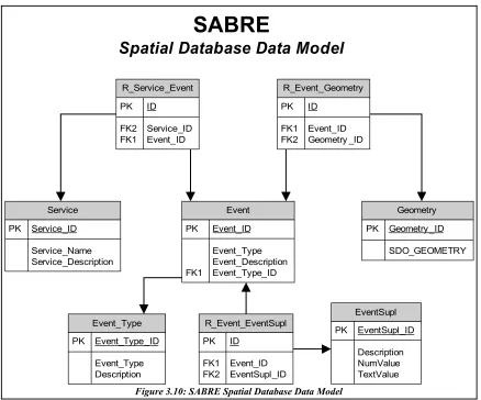
events added in the future to SABRE such as, for example, a Route-event. The three entities service,event and location are the backbone of the data model, therefore these entities can directly be used as tables, where the location entity is denoted as table Geometry. The idea is that service has a many-to-many relation with Event, each service can consist of multiple events and each event can be used by multiple services. This accommodates for a high degree of customisability, which is required for extensibility. The entity event has also a many-to-many relation with Location, thus the event entity can be seen as a bridge between service and location, providing extra customisability.
There are two other entities called EventSupl and Event_Types which are related to the event entity. EventSupl provides optional, supplemental information for the event entity. Event_Types is an extra table which determines which specific spatial processing function the database has to perform. These tables are necessary to accommodate any future additions which may require additional information and/or the use of other spatial processing functions.
Chapter 3 Design SABRE Application 3.5 SABRE Data Model
As seen in the figure there are in total eight tables in the data model. In the middle of the figure are the three tables which provide the core functionality of SABRE, Service, Event and Geometry. The data types of the columns of the tables can be found in appendix B.
The data model as described is according to the first requirement for the data model, extensibility. However, the other two requirements, performance and scalability suffer from this design. For optimal performance and scalability the number of tables used should be kept to a minimum, possibly even only one, because for each table used in a query there is a costly join needed. Even if a simple query is performed on this data model all eight tables are needed and joined together, which can have a serious impact on the performance and scalability when the number of rows in each table increases. Therefore the current form of the data model uses the minimum amount of tables while still obeying to the requirement of extensibility. If any table would be taken out of the data model the SABRE application would loose its extensibility. Other data model designs haven been taken into consideration, although none of them provides the high degree of extensibility this model does. Since LogicaCMG expects the SABRE application to be greatly extended in the near future, if it shows promising results, they required SABRE to have a high degree of extensibility. Therefore the current form of the data model had to be adopted. The performance and scalability requirements were subject to the extensibility requirement. As long as the requirement of extensibility takes precedence over the requirements for performance and scalability the current data model is under the circumstances optimal for SABRE.
Chapter 3 Design SABRE Application 3.6 Design Choices
3.6 Design Choices
The design of SABRE is accompanied by several design choices whereas the choices are heavily dependant on the non-functional requirements. The relevant design choices that need to be discussed are addressed below.
3.6.1 Division into three separate databases
The Database component is required for storing, retrieving and updating data. Both processing of standard and spatial data is required for SABRE. A simple widely adopted solution is to use a single database which can also handle spatial data next to standard non spatial data. Most designs contain only one single database, aspects that favour for a single database are:
✔ Manageability
✔ Cost
✔ Maintainability
✔ Compatibility
The SABRE application however uses three independent databases, each database has its own specific functionality. The motivation for usage of three instead of one database is the performance aspect. The performance of the spatial processing of the database has to be maximized in order to handle as many requests per second as possible. To maximize the performance of spatial processing all other non-spatial processing has to be minimized as they influence the performance in a negative manner. The best solution is to isolate the spatial processing and set up a database dedicated to spatial processing only. The idea behind this concept is that SABRE requires different types of time-related data processing, spatial processing is time-critical because of response time requirements, whereas other non-spatial requests are less time-critical or not time critical at all. Therefore the database component consists of the following three databases.
✔ DB I: Spatial Database (SDB)
○ High performance DB, only for spatial processing.
✔ DB II: Web service Database (WSDB)
○ Medium performance DB, supplies specific functionality for the WS.
✔ DB III: Non Spatial Database (NSDB)
○ Low performance DB, used for additional, non time critical, functionality.
Each database is dedicated to a specific purpose, whereas the databases can be divided based on their performance requirements. By this design SABRE achieves maximum performance for its spatial processing in order to handle as many requests per second as possible, which is essential to the performance requirement.
3.6.2 Data Model
The data model has as stated before three requirements of which the first and most important is extensibility. The other two requirements performance and scalability are seriously reduced by the first requirement. If we would design the data model for performance and scalability it would reduce the extensibility. Either way around there is no ideal solution to this problem. There are two possibilities to compensate:
Chapter 3 Design SABRE Application 3.6 Design Choices
2. Create a data model designed for performance and scalability, try to implement extensibility in a later stage by other means.
As stated before the requirement for extensibility takes precedence over the other two requirements therefore the data model is based on extensibility and the first possibility for compensation is used. There is also another reason for choosing to base the data model on extensibility, the first possibility, improve performance and scalability in a later stadium, seems to be very feasible and a realistic possibility. There are two ways to compensate for the high amount of tables used in the data model, these are optimizations on the database level. These optimizations are:
✔ SQL Tuning, improve the query as to minimize the amount of joins required.
✔ Materialized Views, create a precomputed view to eliminate joining completely.
The optimizations are discussed in chapter 5.
3.7 Chapter Summary
4 SABRE Prototype
This chapter describes the realisation of an prototype based on the SABRE design as discussed in chapter 3. The requirements of the prototype are discussed, next the implementation and realisation are described followed by an evaluation of the prototype. This chapter addresses the following research question: “How can the scalable database-design be implemented?”
The SABRE prototype is an implementation of SABRE solely made for this research project. The purpose of the prototype is to provide a means to research the performance and scalability of SABRE. The prototype contains only the bare necessities to accommodate the research and to be a profound realisation of SABRE as well.
4.1 Requirements
The requirements for SABRE have been discussed in chapter 3, the SABRE prototype is based on these requirements, nonetheless the optional requirements are left out. The processes that are not
The data model, as described in chapter 3, is essential to the functionality of SABRE, therefore the prototype implements the data model and adheres to it.
The SABRE prototype design focusses on the database component. Following the SABRE design the database component consists of three databases, the prototype however, implements only one database, the spatial database. The other two databases are outside the scope of this project.
The prototype consists of a front-end, a web service and a spatial database. The front-end constructs a request in XML and sends the request to the web service. The web service takes the request and queries the spatial database based on the request. The spatial database returns the request-responses to the web service which in turn sends the results back to the front-end.
The front-end must be able to formulate a XML-request including a coordinate, defined by an X and Y value, and a service_id. Next to creating the request the front-end is responsible for displaying the results to the user. The web service takes the XML-message from the front-end and extracts the coordinate and the service_id. The web service passes the coordinate and the service_id as arguments of a function to the database. The database processes the function and returns the results to the web service.
Figure 3.5 'SABRE sequence diagram, Basic view' shows the sequence diagram of the SABRE design which is almost the same for the prototype. The only difference is the absence of credentials and the service provider part being replaced by the front-end. The front-end simulates the part of the service provider, it creates and sends requests to the web service, which results in an environment suitable for the performance and scalability testing of this project. Since the front-end only creates and sends requests to the web service, it does not have any performance impact.
Chapter 4 SABRE Prototype 4.1 Requirements
prototype to still be able to check if a coordinate lies within a certain area, an area has been redefined as a point with a certain radius. The radius creates a circle around the point with a diameter of twice the radius, so the circle can be considered to be an area. The checking of the coordinate is now done by checking if the given coordinate lies within distance of the points associated with the required service. If the given coordinate lies within distance of the point, it is said to be within an area. For every point that lies within distance of the given coordinate the name of the point is returned to the web service instead of IN or OUT.
4.2 Implementation Prototype
The implementation and realisation of the prototype can be roughly divided into three parts, together these parts make up the SABRE application. The first part, the data model, focusses on the implementation of the SABRE data model into the prototype. The second part, the SABRE package, focusses on the SABRE package which provides the required functionality of the database. The third and last part, the web service, focusses on the realisation of a web service component.
4.2.1 Realisation SABRE Data Model
The core of the prototype is the SABRE data model. The data model is implemented in a spatial database, Oracle Spatial 10g. The data model is implemented in the database so that each entity in the data model represents a table in de database. The relation between the tables are based on the primary keys and foreign keysof the tables, accordingly to the data model.
Tables are created with a basic create table syntax. The lines of code to create the tables in the Oracle Spatial 10g database can be found in appendix C. There are three different data types used for the columns in the tables, NUMBER, VARCHAR2and SDO_GEOMETRY. A Varchar2 is a data type which supports multiple different characters, in this case up to 4000, therefore the data type can support text, whereas the number data type can only contain one number. The number has in some cases a constraint applied, 'not null', which indicates that there must always be a value present for that column. The SDO_GEOMETRY data type is a specific data type for Oracle Spatial, this data type is required for spatial processing. The SDO_GEOMETRY data type is a complex data type and contains coordinates of a location. Appendix D provides additional information about the SDO_GEOMETRY data type. The relations between the tables are based on primary and foreign keys, the lines of code which establish the relations can be found in appendix E. A foreign key from one table references a primary key from another table, thereby establishing a relation between two tables. There are also some other constraints present, these constraints apply to the tables used to establish a many-to-many relation, the constraint enforces that the combination of two values is unique for the table the constraint applies to. This enforcement is necessary to prevent having multiple identical rows in a table, which eventually would lead to duplicate query-results, which is not desirable. The constraint only applies when records are inserted or updated, which does not occur with the prototype. Therefore there is no potentially caused performance impact by the constraints for the prototype.
Chapter 4 SABRE Prototype 4.2 Implementation Prototype
The figure shows the unique numbering mechanism for the Service table, for all other tables the same procedure applies, in an analogue manner. The idea is to create for each table a corresponding sequence, initially set at zero, each call to 'sequence.nextval' increments the specific sequence by one. The call to 'nextval' is issued by a trigger which is triggered just before an insert statement takes place. The trigger retrieves the value of 'sequence.nextval', which is the current sequence number incremented by one, and sets the value for the currently being inserted row. The final effect is that on each inserted row automatically an unique number is applied, which is used by the database to uniquely identify the row. The usage of triggers and sequences comes with a small, nowadays insignificant, cost, on each row inserted there is a little extra overhead. However, the overhead occurs only when the unique-numbering mechanism is applied. Thus there is only overhead when new rows are inserted, which does not occur with the prototype. Therefore the performance of the prototype is not influenced by the unique-numbering mechanism.
4.2.2 Realisation SABRE Package
The spatial database contains a package, a package is a group of procedures, functions, variables and SQL statements created as a single unit which is used to store together related objects. The SABRE package contains stored procedures, which contain the actual SABRE SQL-code. The package is written in PL/SQL[4.1]. The PL/SQL package, containing functions, is published to the web service, the functions can be called from within the web service by addressing a specific function inside the package. The package is responsible for querying the database and returning the results to the web service. The package is called SABRE, its code can be found in appendix F.
A package consists of a package specification, or header, and the package body which contains the actual code. Figure 4.2 shows the package specification of package SABRE.
The SABRE package contains three different functions:
✔ SABRE (number x, number y, number service_id), see figure 4.3
✔ WD (number x, number y, number service_id), see figure 4.4
✔ NN (number x, number y, number service_id)
1 CREATE SEQUENCE "SERVICE_ID_SEQUENCE" MINVALUE 1 MAXVALUE
2 999999999999999999999999999 INCREMENT BY 1 START WITH 1 CACHE 20 NOORDER NOCYCLE ;
3
4 CREATE OR REPLACE TRIGGER "SERVICE_ID_TRIGGER"
5 BEFORE INSERT
6 ON service
7 REFERENCING NEW AS NEW
8 FOR EACH ROW
9 BEGIN
10 SELECT service_id_sequence.nextval INTO :NEW.service_ID FROM dual;
11 END;
12
13 ALTER TRIGGER "SERVICE_ID_TRIGGER" ENABLE;
Figure 4.1: The Oracle unique-numbering mechanism
1 CREATE OR REPLACE PACKAGE "SABRE" AS
2 function NN (X IN NUMBER, Y IN NUMBER, SID IN NUMBER) return places;
3 function WD (X IN NUMBER, Y IN NUMBER, SID IN NUMBER) return places;
4 function SABRE (X IN NUMBER, Y IN NUMBER, SID IN NUMBER) return places;
5 END SABRE;
Chapter 4 SABRE Prototype 4.2 Implementation Prototype
(The x and y in the function call represent the coordinates (x,y) of a location.)
The package's main function is function SABRE, which can be seen as the entry point of the package. Function SABRE receives as input-values the coordinates and the service id. Based on the service id the function determines which function to call next, WD or NN. The PL/SQL-code of function SABRE is displayed in figure 4.3.
By addressing the view 'service_2_event', which maps services onto events, the SABRE function determines the event_id that corresponds to the given service_id. Next, by looking up the event, from its id, the function can determine the service type. By the number of the service type the function knows which function to call next. This is an simple but effective mechanism to support calling of different functions. Therefore, multiple new functions can be added, which supports extensibility. This mechanism seems rather inefficient, for every request the mechanism is used before the actual request is processed, which should lead to extra overhead. However, performance tests have pointed out that there is no significant difference in performance when using this mechanism compared to directly calling the required function. Which is remarkable because of the expected negative performance impact when using this mechanism. A plausible explanation could be that the overhead is of no significance because of the processing power of nowadays computers. While older computer with less processing power could be significantly influenced, the processing power of computer these days is relatively so immense it can process the mechanism so fast it does not cause a negative performance impact any more. This results in the performance impact of the mechanism being insignificant with respect to the processing of the actual request.
The SABRE prototype supports only two spatial operators:
✔ SDO_WITHIN_DISTANCE (SDO_WD), see appendix G.
○ Determines which objects are within a specified distance of each other.
✔ SDO_NN (Nearest Neighbour), see appendix H.
1 function SABRE (X IN NUMBER, Y IN NUMBER, SID IN NUMBER) return PLACES IS
2 BEGIN
8 select e.event_type_id INTO service_type_id from event e, service_2_event s2e
Chapter 4 SABRE Prototype 4.2 Implementation Prototype
○ Determines which object is closest to a specified object.
These spatial operators are encapsulated in the other two functions of the SABRE package. Operator SDO_WD is encapsulated in function WD, whereas operator SDO_NN is encapsulated in function NN. Function WD or NN are called by function SABRE, the required parameters, coordinates and service id, are passed along with the call to function WD or NN. When function WD or NN has finished it passes back the results to function SABRE, which in turn will return the results to the web service.
Function WD is the only function, containing a spatial operator, which is in the scope of this project. Function NN is beyond the scope of this project and is only supported to demonstrate other abilities and, or possibilities of the SABRE application. By simply adding a different spatial operator encapsulated in a new PL/SQL function, completely different results can be obtained, which is a proof-of-concept of the ease of extensibility of SABRE. For this project however, the focus is only on function WD and its spatial operator SDO_WD. The general idea is that SDO_WD compares different geometries and determines whether or not they are within a specified distance of each other. SABRE requires SDO_WD to check a given coordinate against a list of geometries determined by the service id. The PL/SQL-code of function WD is displayed in figure 4.4.
The function contains basic PL/SQL declarations (lines 3-6), the actual SQL-statement containing the spatial operator (lines 7-11) and a mechanism of fetching the results into the user-defined return-type places (lines 12-20). The mechanism for the fetching the results is required for returning the results to the web service, because the web service requires the results of an SQL-statement to be contained within a table because of its implementation limitations.
The SQL-statement returns the names of the geometries within the distance of 500 units of the given coordinate. The distance used is of great influence to the performance of SABRE. The prototype implements only one static value which is set at 500. The value of 500 ensures that each queried dataset returns at least one result. Varying the distance is beyond the scope of this project but would be an interesting aspect for future research. First, the service id is mapped to its corresponding geometries by the 'service_2_geometry view',to create a list of possible geometries for the result-set. Second, the list of geometries is passed onto the SDO_WD operator which checks which geometry is within distance of the given coordinate. To perform a
1 function WD (X IN NUMBER, Y IN NUMBER, SID IN NUMBER) return PLACES IS
2 BEGIN
3 declare
4 wd_rst PLACES:=PLACES();
5 j number :=1;
6 CURSOR wd_cur IS
7 select g.name from geometry g,service_2_geometry s2g
Chapter 4 SABRE Prototype 4.2 Implementation Prototype
within distance check the given coordinate needs to be transformed into a geometry first, after which spatial processing can take place. Finally, only the names of geometries corresponding to the service id and which are within distance of the given location, are returned. Hence the return-type 'PLACES'. which is a user-defined return-type which consist of a table containing text, the names of the geometries in the result set.
4.2.3 Realisation Web Service
The realisation of the web service for the SABRE prototype is a fairly easy straightforward process. The entire web service is created and instantiated by Oracle Containers for JAVA[OC4J] (OC4J), with the aid of Oracle's integrated development environment called JDeveloper[JDEV]. The only aspect taken into consideration is the mapping of data types, whilst the web service does not know which kind of data type to expect. JDeveloper does however, know how to map data types as long as they are contained inside a table, as return-type PLACES is, so the web service knows it can expect a table.
The aided realisation of the web service by JDeveloper can be seen as a quick-and-dirty solution, which normally is not adequate for usage in a commercial environment. However, the web service component is beyond the scope of this project, the focus is on the database component. Therefore the prototype has no requirements for the web service, the web service created by JDeveloper is sufficient enough.
4.3 Chapter Summary
5 Optimizations
This chapter contains an in-depth description of the optimizations applied to the database. The goal of applying the optimizations is to improve performance and scalability. The optimization to be discussed are SQL Tuning, Materialized Views and Range Partitioning. This chapter addresses the following research question “Are there possibilities to significantly improve the performance and scalability by means of database optimizations?” Each optimization will be described, it will contain a technical description as well as the expectations of applying the optimization.
5.1 SQL Tuning
Implementation of decent SQL is essential for performance and scalability of a database. An inefficient implementation of a piece of SQL-code may become the main bottleneck in terms of performance for a database. Therefore the possibility of a piece of SQL-code being the main bottleneck must be ruled out. To rule out the possibility all SQL statements have to be analysed. The cost of a query needs to be calculated based on the query execution plan. When the cost is known it is essential to try to lower the cost of a SQL statement as much as possible by altering the statement or applying hints to the execution plan.
Oracle Spatial supports its own spatial index, MDSYS.SPATIAL_INDEX. The spatial index is similar to conventional indexes such as B-Trees. The spatial index is implemented as an R-Tree index, a hierarchical structure, like B-Trees, that stores rectangle approximations of geometries as key values. For each geometry the R-Tree defines the minimal bounding rectangle[5.1] (MBR) enclosing the geometry, and it creates a hierarchy of MBRs. The spatial index has several parameters. By setting the LAYER_GTYPE parameter, it can speed up the query operators thereby enhancing the performance of the index. A technical description of the spatial index can be found in appendix I.
5.1.1 Technical
SQL tuning contains two separate optimizations, tuning the execution plan and the optimization of the spatial index. The performance of the spatial index can be enhanced by including the LAYER_GTYPE parameter when the index is created. The LAYER_GTYPE parameter specifies the type of SDO_GEOMETRY that is being used. Setting LAYER_GTYPE to POINT tells the index that all geometries are points. This results in the index mechanism knowing it only has to operate on points instead of multiple different geometry types so spatial query optimizations will be invoked. Thereby the index can be sped up because it can exclude several steps needed to process different SDO_GEOMETRY types.
Chapter 5 Optimizations 5.1 SQL Tuning
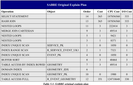
SABRE Original Explain Plan
Operation Object Order Cost CPU Cost I/O Cost
SELECT STATEMENT 14 365 187856560 333
HASH JOIN 13 365 187856560 333
NESTED LOOPS 11 3 222414 3
MERGE JOIN CARTESIAN 9 3 49514 3
NESTED LOOPS 5 1 9421 1
NESTED LOOPS 3 1 8371 1
INDEX UNIQUE SCAN SERVICE_PK 1 0 1050 0
INDEX RANGE SCAN R_SERVICE_EVENT_UK1 2 1 7321 1
INDEX UNIQUE SCAN EVENT_PK 4 0 1050 0
BUFFER SORT 8 3 48464 3
TABLE ACCESS BY INDEX ROWID GEOMETRY 7 3 49514 3
DOMAIN INDEX GEOMETRY_IDX 6
INDEX UNIQUE SCAN GEOMETRY_PK 10 0 1900 0
TABLE ACCESS FULL R_EVENT_GEOMETRY 12 351 124710648 330 Table 5.1: SABRE original explain plan
Figure 5.2 shows the total cost of the query execution plan. The total cost is the cost of all operations.
Total Cost of the Original Execution Plan
Cost CPU Cost I/O Cost
365 187856560 333
Table 5.2: Total cost of the original execution plan
The cost of a execution plan represents units of work or resource used. The query optimizer determines the most efficient way to execute the SQL-statement. The query optimizer uses disk I/O, CPU usage, and memory usage as units of work. So, the cost used by the query optimizer represents an estimate of the number of disk I/Osand the amount of CPU and memory used in performing an operation. The operation can be scanning a table, accessing rows from a table by using an index, joining two tables together, or sorting a row set. The cost of a query plan is the number of work units that are expected when the query is executed and its result produced.
Chapter 5 Optimizations 5.1 SQL Tuning
instruct the Oracle database to use the index instead of a full table access. Before executing a query the database checks if any profiles corresponding to the query are present. If an SQL-profile is present the query is executed by the plan supplied by the SQL-profile. If there is no SQL-profile present the database tries to execute the query as efficient as possible guided by the query optimizer-mode. Most likely the full table access and the hash join are a result of the query optimizer using the 'optimizer_mode = all_rows' setting, the optimizer chooses the best plan for fast delivery of all of the rows that queries return so the optimizer may decide to choose a full table scan over index access and hash joins instead of nested loop.
Hash join operation are, in a Oracle Database, only applied when there is no index present in the to be joined tables and when the tables contain many records. Nested loop operations are generally more efficient than hash join operations when a small number of results hav