ABSTRACT
QIN, XIAOFENG. Deep Insertion of Long Slender Needle into Deformable Tissue and the Application for Prostate Brachytherapy. (Under the direction of Dr. Yuan-Shin Lee.)
This paper presents an analytical modeling and control of long slender needle insertion
for medical surgery applications. Deep insertion of percutaneous needles has become widely utilized in minimal invasive surgery for medical treatments, for example, the brachytherapy treatment for prostate cancer. Long slender needles carrying the radioactive seeds are inserted
into the human body and the seeds are released at the correct locations in the tumor site. The effectiveness of the treatment highly depends on the insertion accuracy of the seeds array.
However, the flexibility of the needles and the deformability of the soft tissue significantly increase the difficulty of accurate insertion. Additionally, the cutting path of the needle is strictly limited by the surrounding organs, vessels, and nerve bundles. The controllability of
the needle and the accuracy of the insertion remain as big challenges to both medical doctors and biomedical engineers.
This study presents a set of novel methods to analyze the insertion process and the coupling effect between the flexible needle and the soft tissue during the deep insertion. A novel stage-wise differential beam modeling of medical needle insertion processes is proposed
to improve the accuracy of deep insertion. A backward compensation technique is developed to serve as a useful preplan tool for brachytherapy surgery treatments. Experiments were
conducted and used for validating the developed analytical modeling.
By developing the analytical modeling and the corresponding methodologies, the research offers a tool that helps the medical doctors to analyze and choose the best design
tissue biopsy, drug delivery, and seed planting. The presented techniques can be used in the design and manufacturing of new generation of steerable needles for a wide range of medical
Deep Insertion of Long Slender Needle into Deformable Tissue and the Application for Prostate Brachytherapy
by Xiaofeng Qin
A dissertation submitted to the Graduate Faculty of North Carolina State University
in partial fulfillment of the requirements for the Degree of
Doctor of Philosophy
Industrial Engineering
Raleigh, North Carolina 2015
APPROVED BY:
________________________________ ________________________________ Dr. Jingyan Don Dr. Paul Cohen
________________________________ ________________________________ Dr. Roger Narayan Dr. Jason Z. Moore
________________________________ Dr. Yuan-Shin Lee
ii DEDICATION
I dedicate this dissertation work to my parents, Ming Qin and Weiya Li for their six
years’ encouragement and support. I also dedicate this dissertation to my beautiful wife, Wenjun Gao for everything she has done for me during these wonderful years. I would never
iii BIOGRAPHY
Xiaofeng Qin was born in Changchun, China. He is a Ph.D. student in the Edward P.
Fitts Department of Industrial and System Engineering at North Carolina State University, U.S.A. He received his B.S. (2010) degree in Information and Electronics Engineering from
Zhejiang University, China and his M.S. (2012) degree in Industrial Engineering from North Carolina State University, U.S.A. His research interests include Reverse Engineering (RE), Computer Aided Design and Manufacturing (CAD/CAM), computational geometry for design
and manufacturing, human-haptic interface, regenerative medicine, design and analysis of medical devices, physically-based simulation for medical applications including surgical
iv ACKNOWLEDGMENT
I would like to express my deep appreciation and gratitude to my advisor, Dr.
Yuan-Shin Lee, for his support, patience, suggestion, and encouragement during my academic and research work at North Carolina State University. Without his valuable guidance and
continuous support, I would never have finished my study. I would like to express my gratitude to Dr. Roger J. Narayan and Dr. Jason Z. Moore for their supports, suggestions, and providing access to their lab equipment. I would like to thank Dr. Paul Cohen and Dr. Jingyan Dong for
their support and serving in my Ph.D. committee. I would also like to thank Dr. Sandra Paur for her serving as my graduate representative.
I sincerely thank my research group members: Dr. Plawut Wongwiwat, Dr. Apichart Boonma, Peter Prim, Yang Yu, Wenqi Ma, Hantang Qin, Yi Cai, Pedro Huebner, and Arjun K Nair for their discussions, suggestions, friendship, and inspiration. I would also like to thank
the visiting professors to our research group, Dr. Chunquan Li, Dr. Jialiang Zhang, Dr. Kim, Dr. Fanxia Kong, Dr. Rufeng Xu for their valuable suggestions and discussions. In addition, I
would like to thank Ryan Boehm and Andrew Barnett for their suggestions and support in training and setting up lab equipment. At last but not least, I would like to thank Dr. Harvey West and Daniel Leonard for the suggestions and support during preparation of the final
v TABLE OF CONTENTS
LIST OF TABLES……...………...viii
LIST OF FIGURES………....ix
CHAPTER 1..………...…1
1.1. Motivation ... 1
1.2. Research Objective ... 3
1.3. Organization of the Dissertation... 5
CHAPTER 2……….. ... 8
2.1. Introduction ... 8
2.1.1. Prostate. ... 8
2.1.2. Prostate Cancer ... 9
2.1.3. Brachytherapy ... 10
2.1.4. Prostate Brachytherapy... 11
2.2. Long Slender Needle Insertion ... 12
2.3. Needle Steering ... 14
2.3.1. Needle Tip Steering ... 14
2.3.2. Needle Base Manipulation ... 18
2.3.3. Tissue Manipulation ... 20
2.3.4. Friction and Cutting Force ... 22
2.4. Fracture Mechanics and J Integral ... 23
2.4.1. Current Applications ... 25
2.5. Challenges and Opportunities ... 26
2.5.1. Uncertainty of Motions within the Tissue ... 26
2.5.2. Potentials of Tissue Damage ... 26
2.5.3. Combination of Human Control and Robot Assistance ... 27
2.6. Summary ... 28
CHAPTER 3……….. ... 29
3.1. Introduction ... 29
3.2. Two Phase Insertion Process... 33
3.2.1. Phase One Insertion ... 35
3.2.2. Phase Two Insertion ... 37
3.3. Model Application and Discussion ... 41
vi
3.3.2. Needle Buckling In Homogenous Tissue ... 42
3.3.3. Needle Buckling In Multi-Layered Tissue ... 45
3.4. Summary ... 47
CHAPTER 4……….. ... 48
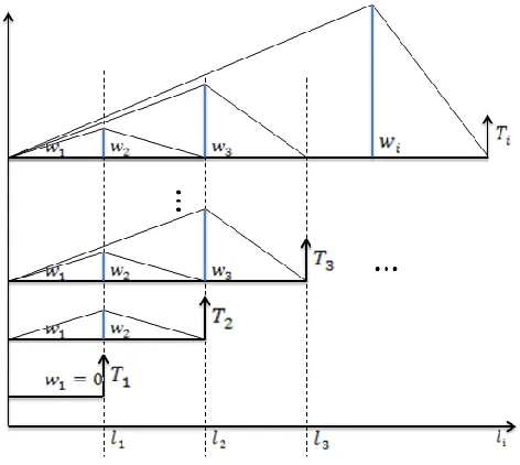
4.1. Stepwise Needle Insertion Modeling ... 48
4.2. Three Phase Insertion: ... 52
4.2.1. The Starting Phase ... 52
4.2.2. The Steady Phase ... 56
4.2.3. The Transition Phase ... 63
4.3. Model Changing Mechanism ... 65
4.4. Tissue Modeling and Friction Force Approximation ... 65
4.5. Differential Model and Dynamic Segmentation ... 68
4.6. Optimal Swiping Surface in Three Dimensional Cases ... 71
4.7. Summary ... 72
CHAPTER 5…………. ... 73
5.1. Backward Compensation ... 73
5.1.1. Backward Compensation Based on Primary Beam Model ... 73
5.1.2. Backward Compensation Based on Advanced Needle Model ... 78
5.2. Lab-Built Experiment Set Up ... 84
5.3. Summary ... 87
CHAPTER 6……….. ... 88
6.1. Analytical Modeling Simulation ... 88
6.2. Haptic Simulation ... 92
6.3. Results Based On the Differential Beam Model ... 96
6.4. A Design of Case Study... 101
CHAPRER 7………….. ... 103
7.1. Design of Experiment ... 103
7.2. Rupture, Friction and Insertion Force... 109
7.3. A Case Study of the Insertion Force Estimation ... 119
7.4. The Effect of Needle Tip Geometry and Vibration... 122
7.5. Needle Deflection and Cutting Path ... 129
7.6. Validation of Simulation Results from Experiment ... 137
viii LIST OF TABLES
ix LIST OF FIGURES
Figure 1.1 G17 bevel tip biopsy needle (upper), G17 symmetric tip brachytherapy needle set
(mid), G18 symmetric tip brachytherapy needle set (lower)………. …2
Figure 2.1 Prostate and surrounding tissue cross section anatomy [Nordqvist 2009]……... …9
Figure 2.2 Nonholonomic needle model [Webster 2006]………. ..14
Figure 2.3 Needle steering mechanism [Webster 2006]……… ..15
Figure 2.4 Torsional friction model [Reed 2009]………. ..17
Figure 2.5 Manipulation Jacobian and potential field from [DiMaio 2005]………. ..19
Figure 2.6 Needle insertion schematic from [Mallapragada 2009]………... ..21
Figure 2. 7 The facture mechanics at the needle tip……….. ..23
Figure 3.1 (A) Tru-cut and (B) End-cut needle biopsy, [Moore 2011]………. ..30
Figure 3.2 The basic model of the needle……….. ..33
Figure 3.3 Cantilever beam with string tissue support……….. ..35
Figure 3.4 Force and moment equilibrium diagram of cantilever beam with string tissue support………... ..36
Figure 3.5 Needle buckling condition ………..38
Figure 3.6 The bending moment model of the needle………... ..39
Figure 3.7 Bevel tip needle buckling in the air……….. ..41
Figure 3.8 Needle model in two layered tissue……….. ..45
Figure 3.9 An example of two layers load components………. ..46
Figure 4.1 micro-bristle type friction model [Asadian 2014]………...50
Figure 4.2 Trapezoidal friction profile [Asadian 2014]………...52
Figure 4.3 Starting Phase normal force profile……….. ..53
Figure 4.4 Differential model approach in Starting Phase………. ..53
Figure 4.5 Normal force profile in Starting Phase………. ..54
Figure 4.6 Stepwise optimal needle shape function………...55
Figure 4.7 Chain of cantilever beam model………... ..57
Figure 4.8 Needle segment end force balance………... ..59
x
Figure 4.10 Normal force profile on the chain of cantilever beam model……… ..61
Figure 4.11 The simplified normal force profile………... ..62
Figure 4. 12 Illustration of the normal force along the needle shaft within Transition Phase……….. ..63
Figure 4.13 Approximated normal force profile within Transition Phase………. ..63
Figure 4.14 Deformation map of marked target in soft tissue………... ..66
Figure 4.15 Uniform dynamic segmentation………. ..70
Figure 4.16 Linear dynamic segmentation……… ..71
Figure 5.1 Insertion with offset 𝑡………... ..74
Figure 5.2 Insertion with angle 𝛼………. . ..75
Figure 5.3 Insertion with the combination of (𝛼, 𝑡)……….. ..76
Figure 5. 4 Rotational and Translational movement of the needle tip………...78
Figure 5.5 Cutting path and target movement in starting stage………. ..80
Figure 5.6 Insertion with offset 𝑡……….81
Figure 5.7 Insertion with angle 𝛼………...82
Figure 5.8 Insertion with angle 𝛼 and offset t……… ..83
Figure 5.9 Experiment set up………. ..84
Figure 5.10 System coordinate set up and target injection………...85
Figure 6. 1 Needle deflection with various insertion angle...90
Figure 6. 2 Comparison of various needle materials...91
Figure 6. 3 Comparison of various rupture forces... ..92
Figure 6. 4 Haptic interface of needle buckling and bending simulation... ..93
Figure 6. 5 Straight needle model with upward bevel tip and handle (left) and two layer tissue model with bone (right)...93
Figure 6. 6 Needle start to insert into tissue (left) detailed illustration (right)...94
xi Figure 6. 8 Needle fully inserted into both layers (left) needle bending inside two layer
tissues. Tissues are graphically removed to show the needle shape inside (mid) detailed
illustration (right)... ..94
Figure 6. 9 When tissue is soft, needle buckling occurs when further inserted after touching the bone (left) detailed illustration (right)... ..95
Figure 6. 10 Gauge 18 needle insertion into a. hard, b. medium, c.soft tissues. d. needle at rest as control...95
Figure 6. 11 Needle insertion with bevel angle of 40𝑜...97
Figure 6. 12 Needle insertion with bevel angle of 50𝑜...97
Figure 6. 13 Needle insertion with bevel angle of 60𝑜...97
Figure 6. 14 Needle insertion with bevel angle of 70𝑜...98
Figure 6. 15 Needle insertion with bevel angle of 80𝑜...98
Figure 6. 16 Stribeck Effect during a bevel 40𝑜 needle insertion...99
Figure 6. 17 Interface of the Insertion Calculator...100
Figure 6. 18 The Insertion Calculator generates the cutting path with a different angle...102
Figure 7.1 Lab made bevel tip needles……….. 104
Figure 7. 2 Electric Discharge Machining………. 104
Figure 7. 3 Experiment set up ………107
Figure 7. 4 Bevel 45o needle insertion friction test………... 109
Figure 7. 5 The maximum force during the first insertion………. 110
Figure 7. 6 The maximum force during the second insertion ………110
Figure 7. 7 The difference between the first and second insertions………...111
Figure 7. 8 Bevel 45o needle rupture force profile at 10mm/s……….. 112
Figure 7. 9 Fourier fitting of rupture force at 10mm/s insertion……… 113
Figure 7. 10 Fourier fitting of smoothened rupture force data……….. 114
Figure 7. 11 Fourier fitting of rupture force at 5mm/s insertion……… 115
Figure 7. 12 Fourier fitting of rupture force at 15mm/s insertion……….. 116
Figure 7. 13 Fourier fitting of bevel 30o needle insertion at 10mm/s……….. 117
Figure 7. 14 The bevel 45o needle deep insertion force profile……… 120
xii
Figure 7. 16 Material property tested with Shore Durometer ………122
Figure 7. 17 Example of force profile of deep insertion……… 123
Figure 7. 18 Maximum insertion force……….. 124
Figure 7. 19 Poking force………...125
Figure 7. 20 Relaxation turning point……… 125
Figure 7. 21 P-P value shows a negative correlation with bevel angle……….. 126
Figure 7. 22 Homogenous tissue phantom with cutting paths………... 127
Figure 7. 23 Comparison among different vibration conditions on bevel 60oneedle……... 128
Figure 7. 24 Bevel 15oneedle deflection inside homogenous tissue phantom………. 130
Figure 7. 25 Inter-needle distances………... 130
Figure 7. 26 Bevel 30oneedle deflection inside homogenous tissue phantom……….. 131
Figure 7. 27 Bevel 45oneedle deflection inside homogenous tissue phantom………. 131
Figure 7. 28 Bevel 60oneedle deflection inside homogenous tissue phantom……….. 132
Figure 7. 29 Bevel 16oneedle deflection inside homogenous tissue phantom……….. 132
Figure 7. 30 Example of reproduced insertion trajectories……… 133
Figure 7. 31 Bevel 45𝑜 needle insertion into multilayer tissue phantom at 5mm/s……...136
Figure 7. 32 Bevel 45𝑜 needle tip (solid and hollow)………...137
1 CHAPTER 1
INTRODUCTION
1.1. Motivation
Prostate cancer is the most common cancer in American men, other than skin cancer.
A recent report from American Cancer Society shows estimation that about 233000 new cases of prostate cancer would be diagnosed in the year 2014. Prostate cancer is also the second
leading cause of cancer death, right after lung cancer. About 29480 deaths from prostate cancer are estimated for the year 2014 in United States.
Brachytherapy is a radioactive treatment always applied for cancer remedy on the early
or intermediate stages, such as breast cancer, prostate cancer, cervical cancer, etc. The word segment “brachy” originally comes from Greek, which means “fast”. After only a few decades
of the discovery of X-ray, the first brachytherapy was invented in 1920s to treat patients suffering from tumors. However, at that early stage, both the dosimetry and the device were
2 Figure 1.1 G17 bevel tip biopsy needle (upper), G17 symmetric tip brachytherapy needle set
(mid), G18 symmetric tip brachytherapy needle set (lower)
Prostate brachytherapy with iridium source was first used in 1958and became known
by people with a preliminary report by Holm in 1983. [Winston 1958, Beyer 2001] 125I radioactive seeds with the dimension of 4.5mm in length and 0.8mm in diameter are implanted
into the prostate gland by a long slender 18 gauge needle. Usually about 70-150 seeds are implanted into prostate during the therapy according to the pre-planned dose map. Great
limitations were confronted during 1970s and 1980s due to the inaccuracy of the seed implantation. The performance was enhanced later on owing to the support of modern image technologies like ultrasonic imaging, CT scan MRI, etc. However, due to the complicated
mechanism of needle tissue interaction and multiple parameter variations from patients to patients, there is much room for improvement.
3 site and a low temperature is applied on the tip to kill the cancerous cells or decrease the cellular metabolism.
In all these aforementioned long slender needle based treatments, the accuracy of the insertion is always the major challenge. Especially in prostate brachytherapy, due to the
deformation of the soft tissue and the flexibility of the long needle, the misplacement of the seed and the insufficient dose rate resulting from the misplacement reduces the performance of the treatment. Medical centers and clinics employ a variety of customized algorithms for
pre-planning process before the surgery. Again, no consensuses have been achieved in the society. The researchers are contributing great effort to enhance the performance of needle
insertion system.
1.2. Research Objective
The objective for this study is to enhance the efficiency, accuracy, and controllability of the needle steering and seed planting for brachytherapy by a deep investigation of the
behavior of the flexible bevel tipped needles insertion into the soft tissue. The investigation and development of fast computational and modeling techniques helps to effectively represent, demonstrate, and predict the interaction between the long slender needles and the soft tissue.
This can happen by pursuing a study of multistage dynamic needle tissue coupling model instead of focusing on either of them independently. The approach will then be used in design
4 Beam Bending and Buckling Mechanics, Fracture Mechanics, Finite Element Modeling, etc. are employed to develop the new methodologies. However, percutaneous needles have a large
variety of tip geometries due to different applications. This study majorly focuses on the bevel shaped needle tip, which is the most typical and controllable type yielding reasonable curvature
and acceptable damage to the surrounding tissues during the deep insertion process. The study of the behavior of the bevel tipped needles in deep insertion will serve as a building block to pave the way of the future study with more complicated needle geometry in a wide range of
situations.
The following topics are addressed in our study.
1. Needle bending and buckling effect during the insertion process. A two phase process base on Beam Theories is proposed to assist understanding the mechanism of the insertion within a non-deformable material. The analysis of the effect of different bevel
tip parameters and needle materials is conducted. The parameters that reflect tissue and needle stiffness such as Young’s modulus and Poisson ratio are assigned explicitly and
can be used to characterize different material properties.
2. Study of high fidelity needle behavior modeling. Micro and Macro friction models including Stribeck Effect are employed to pursue an accurate needle tissue interaction.
A continuum mechanics based methodology such as Finite Element (FE) analysis is utilized to investigate soft tissue deformation during the process of needle insertion,
5 way to support the backward compensation. A novel dynamic segmentation method is proposed to explain the gradual change of the needle behavior during insertion.
3. The design of experiment to validate the developed technique including device setup is
presented. The applied force generated from flexible needle penetration into the tissue sample, the deformation of the sample, the force and torque feedback at the handle can be measured and collected. Backward compensation approach to help locate the
original target position before deformation is introduced to enhance the accuracy of seed placement.
4. Assessment of selected needle designs with various parameters using the developed method and platform. The force profile and the needle deflection of the entire deep insertion process are obtained with methodology provided and a short pre-insertion.
The experiments validate the proposed methods.
1.3. Organization of the Dissertation
The remainder of this dissertation is structured as follows:
Chapter 2 briefly reviews previous researches in the related fields, including
introduction of slender flexible needles and its applications, prostate cancer, brachytherapy, mechanics of needle steering, needle tissue interaction, friction models, Finite Element
6 Chapter 3 presents an overview of modeling and computation techniques that can be applied in the study of flexible needle insertion into soft tissue. A two phase insertion process
based on a cantilever beam model is proposed to investigate the interaction mechanism of the insertion. This chapter also discusses the bending and buckling issues under various conditions.
Further details of the method and advanced promotion will be discussed in the following chapters.
Chapter 4 introduces the multistage needle tissue coupling insertion model. The
concept of differential model and optimal swiping area are proposed to determine the needle shape function under a quasi-static process. The cutting path is also modeled based on the
combination of the derived needle shape function and a developed Linear Elastic Finite Element method. A novel dynamic segmentation is proposed.
Chapter 5 presents the backward compensation approach for accurate target hitting. A
set up of a test station to validate the above approaches is also presented. The experiments is conducted later to validate the full set of approaches while the data collected will be applied in
parameter selection for the new designs of biomedical needles.
Chapter 6 presents the results and discussions based on the analytical model and haptic simulation. The needle deflection and tissue deformation with various insertion conditions,
material properties and needle tip geometries are provided
Chapter 7 presents the major experiment, data analysis, validation of analytical models
8 CHAPTER 2
LITERATURE REVIEW
In this chapter, we review the previous researches that are related to brachytherapy technologies, soft tissue modeling, flexible needle modeling, finite element method, needle
steering. The recent researches on prostate brachytherapy and their applications will be discussed first. We then present the previous studies related to the research and development
of flexible needle and soft tissue interaction model. Lastly, we will end this chapter with the review of design optimization and the future trends of the device.
2.1. Introduction
2.1.1. Prostate
Prostate is an exocrine gland in the male reproductive system. Prostate is approximately the size of a walnut, which is located under the bladder and in front of the
rectum. There are thousands of tiny glands in the prostate, producing a body fluid that forms part of the semen, protects and nourishes the sperm. The urethra is a tube going from the bladder, carrying the urine and the semen out of the body. As is shown in Figure 2.1, there are
numerous vital organs,vessels and nerve bundles around the prostate, within which, the
9 Figure 2.1 Prostate and surrounding tissue cross section anatomy [Norquist 2009]
2.1.2. Prostate Cancer
Prostate cancer is a disease only affects men. In most of the cases, the prostate cancer
starts in the gland cells and this is named as adenocarcinoma. Prostate cancer is very common in the male community. One study indicates that perhaps 80% of men have at least a trace of prostate cancer in their 70s. [Breslow 2006]
A critical issue to be known is the classification of the cancer, in other words, the type and the stage. The cancer stage helps the doctors define the prognosis, which determines what
therapy to use. For example, in T1 and T2 prostate cancer, the cancerous cells are restricted inside the prostate gland while in T3 and T4, the cancerous cells are spread out to other parts of the body.
10 from a biopsy is detected under the microscope. Gleason score goes from 2 to 10. The higher the score is, the more abnormal the tissue is.
In the early stage of the prostate cancer, T1 and T2, some of the following treatments can be selected.
Radical prostatectomy: During the surgery the prostate is surgically removed.
Conformal radiotherapy: The radiation beams are conformed on the tumor site during the treatment in order to minimize the damage to the surrounding healthy tissues.
Intensity modulated radiotherapy: An advanced form of conformal radiotherapy with variable intensity.
Brachytherapy: Radioactive seeds are implanted into the prostate gland.
2.1.3. Brachytherapy
Brachytherapy is a radiotherapy, where a radiation source is implanted into or next to the area that needs the treatment. Brachytherapy is always considered as a fast treatment for
the early stage of cervical cancer, breast cancer, prostate cancer, skin cancer and many other types of tumors. [Beyer 2001]
Compared to brachytherapy, typical radioactive cancer treatments such as open source
radiotherapy and external beam radiation therapy (EBRT) are better known by people. In open source radiotherapy, a therapeutic radioisotope will be injected to localize the tumor site, while
11 is based on precise needle insertion, directly delivers the radioactive seeds to the target area. These radioactive seeds are encapsulated in a protective shell or wire. This design allows the
device to emit radiation to treat and kill cancerous tissue, but prevents the charge of radioisotope from dissolving in body fluids. In High Dose Rate Brachytherapy (HDR), the
seeds or wires will be removed after the treatment. In Low Dose Rate Brachytherapy (LDR), the seeds are allowed to permanently remain in the human body. As we mentioned before, “brachy” means fast and the irradiation only affects a much localized area around the
radioactive seeds. The hazardous effect of healthy tissue further away from the seeds due to direct exposure to radiation is significantly reduced. Furthermore, after the seeds are implanted,
the movement of the patient or the movement of the tissue within tumor site due to breathing will not cause significant radiation miss-exposure. The seeds tend to retain their correct relative positions to the tumor. Therefore, brachytherapy shows advantages over typical radiation
related treatments that the radiation can be focused on much localized area to efficiently treat the tumor, prohibiting surrounding healthy tissues from unnecessary damage.
2.1.4. Prostate Brachytherapy
As a treatment for prostate cancer, brachytherapy can be given in the following two
12 The sole treatment is an option for patients with low risk prostate cancer, referred to early stage of the cancer with the Gleason score of 6 or less. In this situation, the cancerous
cells are confined within the gland.
The combined treatment is an option for intermediate and high risk prostate cancers
with Gleason score over 7. The sequence of the brachytherapy and EBRT could be altered in different clinics.
2.2. Long Slender Needle Insertion
Percutaneous needle insertion has been widely used by many clinical practices, for
example, biopsies, regional anesthesia, blood sampling, brachytherapy and so on. The effectiveness of a treatment and the precision of a diagnosis are always highly dependent on the accuracy of the percutaneous insertion. Some clinical studies have revealed that the needle
misplacement may be due to human errors, tissue deformation, needle deflection, imaging limitations, image misalignments, and target uncertainty. [Rampersaud 1999, Carr 2001,
Roberson 1997, Hussain 2001, Taschereau 2000, Narayana 1996]
The concept of needle steering has been widely accepted since the beginning of this century. When performing manual needle insertion, physicians and surgeons will depend on
the tactile feedback (haptic feedback) from the tool or and the visual feedback from a 2D medical image of the needle and surrounding tissue. This is an extremely high requirement for
13 Romano compared manual tele-operation to automatic needle insertion. [Romano 2007] Romano employed a slave-master system consisting of an invasive insertion device and a spin
control device. Their study tested the performance of needle steering based on three conditions: 1) both insertion and spin are controlled manually, 2) both insertion and spin are controlled
automatically, 3)the insertion is manually controlled with an open loop control frame while the spin is controlled automatically. The result showed the hybrid control had significantly better targeting accuracy than the other conditions.
Robot-assisted needle steering is regarded has the potential of improving the effectiveness of existing medical procedures. Higher insertion accuracy through more
dexterous control and the acquisition of those targets unreachable by straight needle insertion are considered as great improvements. [Reed 2011] Currently, many research groups are working on building systematic devices to accurately control the needle steering procedure and
more realistic factors are taken into consideration.
Needle insertion is considered as one of the simplest and most minimally invasive
medical procedures. People believe that the shortest path may lead to the minimal damage to the surrounding tissue. Thus, many studies try to find out the shortest path that the needle travels inside the tissues to the target area voiding colliding with the obstacles. However, after
some years of study, a few researchers start to focus on the possibility of success considering the uncertainties involved during the procedure which may due to the deflection of the needles,
14 2.3. Needle Steering
Needle steering has become a widely accepted concept, which includes needle tip
steering, tissue manipulation, needle base manipulation, etc. Many ways of classification of needle steering are mentioned in previous researches that will not be covered in this study.
Advantages and disadvantages of needle steering are primarily related to the relationship between the needle steerability and the length of the needle segment inside the soft tissue. [Reed 2011]
2.3.1. Needle Tip Steering
Needles with asymmetric tip, such as bevel shape, will not usually navigate through a straight path inside soft tissue because of the imbalance lateral force exerted on the tip. Webster developed a nonholonomic model to simulate the steering problem [Webster 2006].
Figure 2.2 Nonholonomic needle model [Webster 2006]
15 model of the bevel shape needle tip is formulated as the model of a bicycle, of which the front wheel has a fixed angle with the rear wheel. In ideal conditions, the needle tip will behave like
a unicycle, which forms a circular trajectory with constant radius. Various pairs of needle and tissue lead to different key parameters. People are able to control the needle tip position and
motion by controlling steering angle. [Alterovitz 2008]
The navigating direction of the needle tip is dominantly controlled by rotating the needle handle at the base. The bicycle model mentioned above rotates as a rigid body about a
center defined by the intersection of the two wheel axes, while the modified planar unicycle model with an angular velocity proportional to its linear velocity. [Webster 2006] The further
navigating of the needle tip is due to subsequent rotation of the needle shaft, which reorients the tip so that further deflection is exerted and new trajectory direction is formed.
16 In this way, the steered needle can follow the paths in any plane by applying insertion and rotation on the base. For example, Alterovitz developed a 2D planning system around the
middle of the first decade of 21 century. Two cameras were employed to supervise the steering procedure that one was used to monitor the needle path from the top of the phantom tissue, and
the other was used to keep the needle navigating within one fixed plane. Following the idea, pre-bent needles were further developed to achieve curved needle paths with larger steerability. [Majewicz 2010] However, during the rotation of the pre-bent needle, discontinuity was
identified and more damage to the surrounding tissue was reported.
As is indicated in Figure 2.4, torsional friction was identified during the insertion of the
steerable needle by Reed. [Reed 2009] Rotating a needle inside the tissue can cause the tip angle to deviate from the base angle due to friction along the needle-tissue interface. Their experiments showed that several common phantom tissues used in needle steering experiments
impart substantial friction forces to the needle shaft, resulting in a lag of more than 45o for a 10 cm insertion depth in some phantoms. Clinical studies also reported that torques large
enough could cause similar errors during needle insertions. There are some methods that mentioned by them to overcome this lag. One of the methods is to retract the needle for a small distance after rotating the needle and then reinsert the needle at the same direction. The
reinsertion will possibly cause the needle to move along the previous path. However, it is not recommended especially when a pre-bent needle is in use, since the procedure may cause more
17 Another method mentioned in the study to avoid lag is dithering. Dithering will add a high-frequency periodical signal onto the insertion. [Olsson 1998] They also mentioned that
dithering will keep the needle tip moving and prevent the controlled surface from encountering adhesion. However, high-frequency motions are not likely to be suitable for needle steering,
due to the possible additional damage to the surrounding tissues.
Figure 2.4 Torsional friction model [Reed 2009]
The study developed several models to simulate the torsional friction. However, currently it is not possible to measure the angle of the needle tip inside tissue. The only angle
measurement is at the base of the needle. Therefore, they employed the rotational dynamic models to estimate the motion of the needle tip for feedback control. Additionally, they also
mentioned that there was a tradeoff between the flexibility of needles for steering and the stiffness of needles to rotate as a rigid body inside the tissue.
Inserting a second concentric pre-bent needle can perform a 2D control of the amount
of curvature at the tip within the insertion plane. [Okazawa 2005] Additionally, incorporating duty-cycled spinning during needle insertion provides proportional control of the curvature of
18 Ko brought up a concept of programmable bevel shape needle, of which the offset between two parts of a probe determines the steering direction of the needle tip due to a set of
bevels included at the tip of each segment. [Ko 2010]
Some of the methods mentioned above allow the radii of curvature to change, but the significant challenge is how to achieve small radii of curvature without damaging the surrounding tissue.
2.3.2. Needle Base Manipulation
Manipulating the base of the needle outside of the tissue can help to steer the needle inside the tissue. Any motion of the needle base perpendicular to the insertion direction causes the tip to move roughly along the reverse direction inside the tissue. DiMaio developed a
needle manipulation Jacobian by using numerical needle insertion models combining needle deflection and soft tissue deformation together. The concept they presented was used in
19 Figure 2.5 Manipulation Jacobian and potential field from [DiMaio 2005]
Glozman presented a robotic system for steering a flexible needle in soft tissue under real-time fluoroscopic guidance. [Glozman 2007] The study used an inverse kinematics
algorithm and calculated the path of tip by maneuvering the base of the needle. They employed forward and inverse kinematics of the needle enabling both path planning and path correction in real time. A virtual spring model of local tissue deformation is provided in this study to
support the forward and inverse kinematics analysis.
The drawback is that the method suffers from depth dependence. As the depth of
penetration increases, the force exerted on the needle base increases as well. The thin needle shaft is very likely to slice into the surrounding tissues when the force goes beyond the threshold as more force need to be exerted at the base to generate the same deviation on the tip
20 base manipulation may be achieved in the entire insertion procedure, since the needle tip steering due to the asymmetric tip shape and imbalance force is almost independent of insertion
depth. [Reed 2011]
2.3.3. Tissue Manipulation
Tissue manipulation has been achieved and performed by hand by physicians during therapies. When a relatively rigid needle is inserted into a soft tissue, it is possible to move the
target into the path of the needle and move the sensitive tissues or other obstacles out of the path. Mallapgragada mentioned that the current methods used in breast biopsy like ultrasound
guiding breast biopsy techniques has several problems with the procedure, such as, the possibility of the complex interaction dynamics between the needle force and the breast tissue displacing the tumor, the need of multiple insertions, the fatigue of the clinicians, patient’s
discomfort and compromising the integrity of the tissue specimen. They presented a concept for real-time manipulation of a tumor using a robotic controller to monitor the image of the
tumor to generate appropriate external force to relocate the tumor at a desired position. Robot-assisted manipulation was employed to apply a controlled external force automatically in real time to make sure the tumor not to deviate from the path of the needle. Their experiment with
21 Figure 2.6 Needle insertion schematic from [Mallapragada 2009]
Torabi also presented a concept based on tissue manipulation in their study on brachytherapy procedures. They developed a phased controller that operates one manipulator at a time using closed-loop imaging feedback. In their study, they employed a stochastic
optimization based planner to optimize a cost function including tissues stress and robustness to disturbances. Their new concept was called as single-point tissue manipulation, in which
they perform selecting target, selecting manipulators and force profiles, selecting manipulation points and stochastic optimization in a sequence.
The probable drawback of tissue manipulation method could be the challenge faced
during deep subsurface targeting procedure. Additionally, 3D tissue manipulation is still in early stage, while the researches mentioned above are based on 2D condition. It is also possible
22 2.3.4. Friction and Cutting Force
Researchers have devoted great efforts to needle tissue interaction from a perspective
of friction modeling, which is always focused on the needle shaft. Okamura measured only the insertion force in an ex-vivo experiment on bovine liver [Okamura 2004]. Three key
components are identified in the study. They are a capsule stiffness force before puncture, a cutting force at the needle tip, a friction force along the needle shaft respectively. A Karnopp model is employed to do the friction force simulation.
DiMaio proposed a force distribution model with a peak close to the needle tip after their simulation and experiment with a video camera tracking system [DiMaio 2005]. This is
named as a Stick-slip model, which intuitively describes the phenomenon when the needle tip reaches a node. The node sticks to the needle and moves along with it until the reaction force exceeds a pre-set threshold. The interaction between the slipping nodes and the needle shaft
results in friction forces.
Other experiment based studies, such as Crouch and Hing [Crouch 2005, Hing 2007]
investigate needle tissue interaction in a 3D environment. However, the current imaging techniques in practice hinder this from patient studies. Asadian employed the LuGre Friction Model and compared the derived and simulated results with experiment results. Their
assumption of a trapezoidal normal force profile facilitated the computation but was not consistent with the real practice. [Asadian 2014]
23 2.4. Fracture Mechanics and J Integral
The fracture mechanics of the tissue phantom is still an active research topic today. To
simplify the complexity of the problem, a nonlinear elastic model is applied to the study. The fracture mechanics of the tissue phantom at the needle tip could be modeled by the
J-Integral.
The J Integral was first introduced in 1967 by Cherepanov [Cherepanov 1967] and in 1968 by Jim Rice. [Rice 1968] The J-integral is a path independent integral to calculate the
strain energy release rate at the crack.
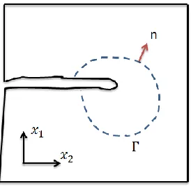
Figure 2. 7 The facture mechanics at the needle tip
As is shown in the figure above, a crack is shown in the square of material. The crack is propagating along the x1 direction. The dashed curve is an arbitrary path that connecting the
24 As the needle is inserted into the tissue phantom, cracks and micro cracks are generated around the needle tip inside the material. The cracks may not be necessarily along the insertion
direction. The strain energy stored in the tissue phantom is released as the new cracks are generated. Thus, the release rate of the strain energy will be critical to determine the driving
force to open the crack.
The general form of the J integral presented is as follows.
𝐽 ≡ −𝑑𝛱 𝑑𝐴
𝛱 = 𝑈 − 𝑊
where, 𝑈is the strain energy of a domain including the crack tip. 𝑊is the work done by
the external forces. 𝐽is the energy release rate over unit area and 𝐴 is the crack area. A path
independent integral formulation was proposed in Rice’s work.
𝐽 = ∬ (𝑤𝑑𝑦 − 𝑇𝑖𝜕𝑢𝑖 𝜕𝑥 𝑑𝑠)
Г
𝑤 = ∫ 𝜎𝜀𝑖𝑗 𝑖𝑗𝑑𝜀𝑖𝑗
0
In the formulation, 𝑤 is the strain energy density. 𝑇𝑖is the traction vector that always
perpendicular to the curve. 𝑢𝑖is the displacement. 𝑑𝑠 is a small unit on the curve.
For linear elastic materials, 𝐽is related to the stress intensity factor K.
𝐽 =𝐾
2
𝐸 (𝑃𝑙𝑎𝑛𝑒 𝑆𝑡𝑟𝑒𝑠𝑠)
𝐽 =𝐾
2
25 In the formulation aforementioned, J is the energy released per unit length along the insertion direction.
2.4.1. Current Applications
Current applications of needle steering are closely related to clinical therapies, biopsies, diagnosis etc. For example, Goldberg at UC Berkeley and Alterovitz at UNC focus their researches on prostate brachytherapy. [Alterovitz 2005] Mallapragada at Vanderbilt University
focused their attention on the breast biopsy. [Mallapragada 2009] Researchers from other universities also discuss the needle steering method in brain surgery [Engh 2006, Minhas
2009], liver surgery [Li 2009, Majewicz 2010], kidney surgery [Wood 2010], spine [Glozman 2006] etc.
However, due to the complexity of the real tissue and many other issues, such as
difficulty of real time image feedback and processing, difficulty in control precision, uncertainties of steering factors, etc. many researchers use phantom tissues with similar
26 2.5. Challenges and Opportunities
2.5.1. Uncertainty of Motions within the Tissue
Current studies of needle steering considering the issue of uncertainty are most based on 2D path planning. Alterovitz conducted researches by modeling the needle tip angle with a
normal distribution. [Alterovitz 2008]. Although some algorithms of 3D path planning have been presented by taking advantage of 3D image techniques, such as ultrasound image and magnetic resonance imaging, some key challenges still remain open these days, including the
uncertainty of motion and sensing, uncertainty of rotational angle of the needle tip inside the tissue caused by torsional friction, especially when the needle is inserted into heterogeneous
materials. 3D tissue deformation is also a challenge to correctly track and locate the target area during the steering procedure. When some of the surgeries need to be done around some part of the human body as the surrounding tissue may tend to move, such as tissue under the
influence of the heart beats, multi-DOF of uncertainties need to be taken into consideration.
2.5.2. Potentials of Tissue Damage
Needle steering is minimal invasive cutting procedure to the surrounding tissues. Cutting may lead to bleeding and swelling. Compared to the traditional needle insertion,
needles with pre-bent tip are more likely to create larger damage to the surrounding tissues, especially when activities like rotations and dithering are performed to navigate the needle to
27 which is likely to cause slicing. However, when needle steering is performed inside some complex real tissues, for example, liver tissues, the micro structure of the tissue remains high
uncertainty. There is always a tradeoff between the steerability of the needle and the stiffness of the needle. To achieve small radius of a path curvature, more flexible needles will be
employed to perform the steering. After the needle is penetrated into the tissue for some depth, it is possible that the needle tip may encounter with hard structures that it cannot cut through. Thus, buckling starts to happen. Although all surgery involves damaging tissue to some extent,
it is still unknown that how significant these types of damage are during needle steering procedure. This is probably a good research branch that, starting from the static and dynamic
model of the needle and soft tissue, considering the possible effecting factors, such as axial force from the base of the needle, friction force exerted on the shaft, the curvature of the needle geometry along the path, the resistant force from both the obstacle and the surrounding tissue,
the possible buckling position and the final steady shape of the needle after slicing into the tissue can be calculated and simulated. From this point, further study such as according to
different operations on certain materials, minimum curvature, types of needles, range of forces and available path group can be defined, which may increase the accuracy and safety of the needle steering procedure.
2.5.3. Combination of Human Control and Robot Assistance
28 processing capabilities of the physicians and surgeons during the manual needle steering procedures. However, more and more unexpected issues are revealed when more practical
experiments are conducted. Take one of the issues raised as an example, the tissue membranes. Reed presented the issue in their study that tissue membrane may cause the bevel shape needle
to slide along the membrane for some distance instead of immediate penetration, which leads to some deviation from the actual path to the pre-planned path. [Reed 2011] It will be hard for the robot to make a quick adjustment especially when the target is close to the membrane.
Therefore, manual manipulation will play a vital role in some complex situations. Training to the physicians and surgeons of manual needle steering with robot assistance is of vital
importance, especially when the situations cannot be formulated prior to the operation.
2.6. Summary
The literature review briefly summarizes the prostate cancer, prostate brachytherapy and the remarkable research works done on the needle steering for prostate brachytherapy.
Remaining challenges, such as uncertainty of movement inside tissues, potential damages to surrounding tissues and controllability issues related to cooperation between human and machines are also presented. Our study is majorly focused on the long slender bevel tipped
29 CHAPTER 3
STATIC MODELING OF FLEXIBLE NEEDLE INTERACTION WITH SOFT TISSUE
This chapter presents the proposed methods of modeling and analysis of flexible needle
behavior when it is inserted into the soft tissue. A two phase insertion process is proposed and we hypothesize the accuracy of insertion can be improved by backward compensation, which
is covered in Chapter 5. Bending and buckling issues during the insertion process are modeled and discussed. This analysis provides an insight understanding and emphasizes the importance of the needle behavior of effective target hitting.
3.1. Introduction
Hypodermic Needle has been one of the most widely used medical devices, with an estimated 16 billion injections administered worldwide since 1853. [Gill 2007] Typical
hypodermic needle is used with a syringe to either deliver drugs to or extract bio-fluid from the body. At present, needles are not only utilized in such tasks. They are also being applied in other applications including biopsies (removing part of tissue for study), brachytherapy
(placing source of radiation into the body), regional anesthesia (cause local insensitive), minimum invasive surgery, neurosurgery, and etc. [Abolhassani 2007] Moreover, needles can
be used as a catheter (draining fluid out of body cavity) and ablation probe (removal of harmful substance from the body).
Biopsy is a term for collection tissue samples, which is commonly used for pathological
30 and end-cut needle biopsy and both of the methods utilize hollow needle and stylet. [Moore 2010] Moore managed to summarize and conduct researches to fill the void in hollow needle
tissue cutting knowledge to facilitate the understanding of this hollow needle tissue cutting biopsy. Figure 3.1 briefly presents the tru-cut and end-cut needle biopsy procedures.
Figure 3.1 (A) Tru-cut and (B) End-cut needle biopsy [Moore 2011]
Brachytherapy, as is mentioned before, is a form of radiotherapy where a radioactive seed is implanted in the body next to the area requiring treatment. The process of inserting the radioactive seed usually a tool called applicator, which could be non-radioactive needles or
plastic catheters. Brachytherapy can be applied to various organs, such as cervix, prostate, breast, skin, and etc. Main advantage of this procedure over other radiotherapy techniques is
31 fabricated from metals, they are sufficiently strong to penetrate human tissues without much effort. However, the control of needles becomes much more difficult when appropriated path
and accuracy of the insertion are required. Deviation from the target could turn a simple medical treatment into a live-threatening operation. Since organs may be located extremely
close to one from another, precise insertion is crucial in order to prevent damage to the surrounding organs and complications that may occur afterwards. Errors in needle insertion may be a result of various reasons including imaging limitations, image misalignments, target
uncertainty, needle deflection, movement of target due to tissue deformation, human errors, and etc.
As a needle is being inserted into the patient, the surgeon must be aware of these errors and able to develop an appropriate action to eliminate, compensate or minimize their effects. Previous studies have defined the mechanics of needle insertion and classified it based on
either the position of needle relative to the soft tissue, or the interaction between them. Different stages in needle insertion involve various parameters such as needle displacement,
tissue deformation, and forces due to tissue deformation, cutting, and friction.
This study majorly focuses on the combined buckling and bending issue that frequently happens during long needle deep insertion process. In previous studies, some remarkable
works have been done on buckling analysis of long needle insertion into soft tissues with extended Euler’s formulation. [He 2007, He 2008] In their study, a beam-columns theory and
32 conical tip, etc. [Podder 2005] However, due to the asymmetry of some of the tip geometries, such as bevel tip, the forces exerted on the needle tip are not balanced. One of the critical
effects resulting from the imbalance is the bending issue. Many great research works have been done on investigating the bending features ([Alterovitz 2005a, Alterovitz 2005b, 2004], etc.
and a non-holonomic model was built based on the bending effect to help to increase the steerability of the flexible needle. [Webster 2005]. However, until today, lack of systematic research work has been conducted on the combination of bending and buckling effect of the
slender needle deep insertion in brachytherapy.
The purpose of this chapter is to investigate the effect of deflection of the needle during
the insertion process due to bending and buckling. This chapter will majorly focus on the buckling and bending issues of the needle when either the needle tip is blocked by some high density tissues or the friction force along the needle shaft is high enough to hinder the needle
from further insertion. The study starts from the investigation of the needle motions and tip positions during the navigation based on previous works from other researchers. A series of
33 3.2. Two Phase Insertion Process
Due to the difference of stiffness and the maneuvering behavior, long slender needles
can be simply categorized into three groups, soft needles, rigid needles, and flexible needles. According to previous work by Dr. Okamura and Dr. Alterovitz the motion of the soft needle,
which is also called as complete flexible needle, follows a curve with a certain radius formulated by a nonholonomic model inside the soft tissue. A rigid needle is considered as the needle with extremely high stiffness and never bends. The flexible needle is the type of needles
in between, which is harder than soft needle but softer than the rigid needle, such as brachytherapy needles. In this study, a flexible needle with relatively small turning effect is
considered to be inserted into a soft tissue. As is shown in Figure 3.2, a basic assumption is
made at the very beginning that the bending angle is so small, that the change of sin θ is
approximated by the change ofθ.
lim
𝜃→0 sin 𝜃
𝜃 = 1 (3.1)
This study mainly focuses on the process after the needle is punctured into the tissue. Thus a set of quasi-static models are proposed latter in this section. The needle shaft inside the
tissue is originally approximated by a cantilever beam with a bevel tip, the angle of which isα.
34 Abolhassani proposed a method considering the needle shaft as a cantilever beam with a support at the tissue entry point. [Abolhassani 2007] The analytical expression of the tip
deflection at each instance is provided as
𝑣 =6𝐸𝐼1 (3𝑀𝑙2+ 𝑅
1𝑙3+ 𝑅2𝑧3+ 𝑃 (2𝑡𝑎𝑛𝛼𝑑 ) 3
) (3.2)
where 𝐸 is the modulus of elasticity, 𝐼 is the area moment of inertia, l is the total length
of the needle, 𝑃 is the point load at the tip orthogonal to the insertion direction(z), 𝛼 is the
bevel angle of the tip and d is the needle diameter. At each instant,𝑀,𝑅1,𝑅2, 𝑧 are the base moment, base force, support force and the length of needle inside the issue. In his study, the
value of M and R1 are obtained from the sensors during the experiment.
Latter in his report, he brought up an idea to model the needle deflection with string
support from the tissue. Therefore, our study will start from here. The reason is as follows. This study is aimed at analyzing the bending and buckling effect of the flexible needle inside soft tissues. Before the needle tip is stopped by hard obstacle or extremely high friction
forces, buckling will not occur. However, the needle shape and tip deflection at this moment will be key factors that determine the situation of further insertion after the tip is stopped.
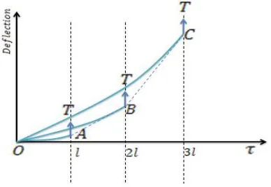
35 3.2.1. Phase One Insertion
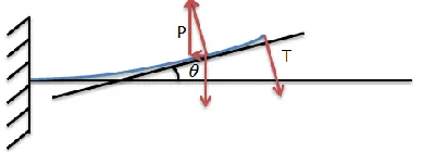
Figure 3.3 illustrates the cantilever beam model with string tissue support. Notice that
the force 𝑀⃑⃑ exerted on the tip can be decomposed into horizontal component P⃑⃑ and vertical
component𝑇⃑ . The relationship between P and T is,
𝑇 = 𝑡𝑎𝑛𝛽𝑃 (3.3)
𝛽 = 𝜃 + 𝛼 (3.4)
where 𝑃 and 𝑇 are the magnitudes of P⃑⃑ and T⃑⃑ respectively. From now on, all the
vectors are represented by their magnitude for simplicity.
Figure 3.3 Cantilever beam with string tissue support
𝜇 is the string constant of the tissue, which is determined by the tissue’s modulus of
elasticity. The string support along the needle shaft will be approximated by a uniformly
36 Figure 3.4 Force and moment equilibrium diagram of cantilever beam with string tissue
support
According to moment equilibrium at the fixed end, we have
𝑀𝑏+ 𝑃𝑣𝑚𝑎𝑥 −12𝑤𝐿2+ 𝑇𝐿 = 0 (3.5)
Referring to Figure 3.4 𝑀𝑏is the moment of the beam at the fixed end and
vmaxrepresents the largest deflection appears at the needle tip. L is the total length of the needle
inside the tissue, while P, T, 𝑤are the corresponding load variables.
Then, by applying the moment equilibrium at an arbitrary point along the beam
𝑀𝑏+ 𝑃𝑣(𝑥) + (𝑇 − 𝑤𝐿)𝑥 +𝑤𝑥
2
2 + 𝑀(𝑥) = 0 (3.6)
where 𝑀(𝑥) is the internal moment at 𝑥 and 𝑣(𝑥) is the corresponding deflection. According to the second order method in Euler Bernoulli beam theory, the internal moment satisfies the following equation
𝐸𝐼𝑣(𝑥)′′ = 𝑀(𝑥) (3.7)
37 By solving Equation 3.4, 3.5 and applying the boundary conditions below
𝑣(0) = 0;
𝑣(𝐿) = 𝑣𝑚𝑎𝑥; (3.8)
𝑣′(0) = 0;
The needle deflection function v(x) and the maximal deflection at the needle tip are
derived as follows.
𝑣(𝑥) = 𝑃 𝑡𝑎𝑛𝛽−𝑤𝐿 𝑃√𝐸𝐼𝑃 𝑠𝑖𝑛√𝐸𝐼𝑃 𝑥 + (𝑤𝐿− 𝑃 𝑡𝑎𝑛𝛽 𝑃√𝐸𝐼𝑃
tan (√𝐸𝐼𝑃 𝐿) − 𝑤𝐸𝐼
𝑃2𝑐𝑜𝑠√𝑃 𝐸𝐼𝐿
) (𝑐𝑜𝑠√𝐸𝐼𝑃 𝑥 − 1) +
(𝑤𝐿−𝑡𝑎𝑛𝛽𝑃 ) 𝑃 𝑥 −
𝑤 2𝑃𝑥
2 (3.9)
𝑣𝑚𝑎𝑥 = 𝑃 𝑡𝑎𝑛𝛽−𝑤𝐿 𝑃√𝐸𝐼𝑃
tan (√𝐸𝐼𝑃𝐿) + 𝑤𝐸𝐼
𝑃2cos (√𝑃 𝐸𝐼𝐿)
+𝑤𝐿2𝑃2−
𝑃 𝑡𝑎𝑛𝛽𝐿
𝑃 − 𝑤𝐸𝐼
𝑃2 (3.10)
Denote
𝑣𝑚𝑎𝑥 = 𝐾
Notice that K is independent of x, which means by setting a group of
parameters𝑇, 𝑤, 𝐿, 𝑃, 𝐸, 𝐼, the value of 𝐾 will be uniquely determined. At this moment, the
needle tip is modeled as a free end and this is the end of the phase one insertion.
3.2.2.Phase Two Insertion
To simulate the buckling effect, we assume the needle is stopped either by a hard obstacle or by extremely high friction force at the tip. In this case, if the axial load is further
38 Figure 3.5 Needle buckling condition
We assume when the needle is stopped, the needle tip reaches the largest deflection,
which was calculated and denoted as 𝐾 in the phase one insertion. Therefore, the needle tip is modified as pinned at the largest deflection as is shown in Figure 3.5.
To keep the variables and mathematical expressions consistent throughout the report,
we use the same set of notations as the phase one insertion to represent the corresponding
values. Notice that𝑃,𝑇, w are no longer of the same values as are shown in the section 3.1. However, since the needle and tissue properties are kept unchanged, the rest of the variables
associated with the material properties are kept unchanged, such as𝐿,𝐸,𝐼.
The force exerted on the tip area consists of two sub forces, with one on the bevel slope
and the other on the tip point. The force exerted on the bevel slope can be further decomposed into a horizontal component and a vertical component. The pinned tip also receives a resistant force that can be decomposed into a horizontal component and a vertical component. The two
39 the tip including the tip point and the bevel slope can be presented by the combination of force
𝑃 and force𝑇, as are shown in Figure 3.6.
Assuming the needle is bending upward and the homogenous tissue stiffness isμ, the
pressure on the needle shaft from the surrounding tissues after further insertion is approximated
by a linearly increasing load distribution with a maximum ofw.
Figure 3.6 The bending moment model of the needle
The moment and force balance are also shown in Figure 3.6. The dashed curve represents the geometry of the needle shaft. We follow all the assumptions made previously in
this report. Some of the values marked in these figures could be negative due to the inversion of the directions.
Similar to the calculation in phase one, according to moment equilibrium at the fixed end, we have
𝑀𝑏+ 𝑃𝐾 +13𝑤𝐿2− 𝑇𝐿 = 0 (3.11)
40 Referring to Figure 3.6, 𝑀𝑏is the moment of the beam at the fixed end and K is the
maximal deflection at the needle tip calculated in phase one. 𝐿 is the total length of the needle
inserted into the tissue, while𝑃,𝑇, w are the corresponding load variables shown in the figure. In equation 3.8, by applying the moment equilibrium at an arbitrary point along the
beam, once can get the following:
𝑀𝑏+ 𝑃𝑣(𝑥) − (𝑇 −12𝑤𝐿) 𝑥 −𝑤𝑥3𝐿3+ 𝑀(𝑥) = 0 (3.12)
where 𝑀(𝑥) is the internal moment at 𝑥 and 𝑣(𝑥) is the corresponding deflection.
By substituting 𝑀𝑏 from Equation 3.11 into Equation 3.12, 𝑀(𝑥) is derived as follows
𝑀(𝑥) = 𝑃𝐾 + 13𝑤𝐿2− 𝑃𝑣(𝑥) − 𝑇𝐿 + (𝑇 −1
2𝑤𝐿) 𝑥 + 𝑤𝑥3
3𝐿 (3.13)
Similarly, by solving the second order differential equation in Euler Bernoulli beam theory and applying the following boundary conditions
𝑣(0) = 0;
𝑣′(0) = 0; (3.14)
The needle shape function is derived as follows.
𝑣(𝑥) = ( 2𝐸𝐼𝑤
𝑃2𝐿√𝑃 𝐸𝐼
+ 𝑤𝐿
2𝑃√𝐸𝐼𝑃
− 𝑇
𝑃√𝐸𝐼𝑃
) sin (√𝐸𝐼𝑃 𝑥) + (𝑇𝐿𝑃 −𝑤𝐿3𝑃2− 𝐾) cos (√𝐸𝐼𝑃 𝑥) +𝑤𝐿3𝑃2+ 𝐾 −𝑇𝐿𝑃 +
41 3.3. Model Application and Discussion
The bending moment and the deflection of the needle are calculated based on Equation
3.1-3.15. The applications of the model in various situations are discussed in this section.
3.3.1. Needle Buckling in the Air
In order to systematically present the application of the approach, we start from the basic condition of needle buckling in the air. Typically, Euler’s Equation is applied to calculate
the sudden failure of buckling in this case as is shown in Figure 3.7
Figure 3.7 Bevel tip needle buckling in the air
The formulation that Euler derived in 18th century is to calculate the maximum axial load on the slender cantilever beam when the buckling occurs. Since there isn’t any bending
effect before the needle buckling, we directly jump to the phase two insertion process. By solving the equation with corresponding boundary conditions, we have
𝑃𝑐 = 𝑛
2𝜋2𝐸𝐼
4𝐿2 (3.16)
where 𝑃𝑐 represents the critical load and n is an integer. The minimal Pc is achieved by
42
𝑃𝑐 = 𝜋
2𝐸𝐼
4𝐿2 (3.17)
3.3.2. Needle Buckling In Homogenous Tissue
Different from needle in the air, the stiffness of homogenous tissue generates resistant forces on both the needle shaft and the needle tip. The proposed two stage insertion method is applied here to calculate the needle deflection.
To avoid the needle buckling outside the tissue, the maximal insertion force can be
calculated with the corresponding parameters. In this case, referring to Equation 3.10, 𝐿 will be the length from the insertion point to the handle. However, the axial load yielding needle
buckling inside the tissue could be influenced by the outside situation, thus we assume the needle will not buckle outside with a well selected insertion point.
Referring back to shape function derived in section 3.3.2, when v(L) = K is applied,
the buckling condition must follow
(
2𝐸𝐼𝑤 𝑃2𝐿√𝑃
𝐸𝐼
+ 𝑤𝐿
2𝑃√𝐸𝐼𝑃
− 𝑇
𝑃√𝐸𝐼)𝑃
sin (√𝑃
𝐸𝐼𝐿) + ( 𝑇𝐿
𝑃 − 𝑤𝐿2
3𝑃 − 𝐾) cos (√ 𝑃 𝐸𝐼𝐿)
=2𝐸𝐼𝑤𝑃2 −𝑤𝐿6𝑃2 (3.18)
If
2𝐸𝐼𝑤 𝑃2 −
𝑤𝐿2
6𝑃 = 0 (3.19)
Then
( 2𝐸𝐼𝑤
𝑃2𝐿√𝑃 𝐸𝐼
+ 𝑤𝐿
2𝑃√𝐸𝐼𝑃
− 𝑇
𝑃√𝐸𝐼𝑃

![Figure 2.1 Prostate and surrounding tissue cross section anatomy [Norquist 2009]](https://thumb-us.123doks.com/thumbv2/123dok_us/1320491.1164860/24.612.198.480.67.284/figure-prostate-surrounding-tissue-cross-section-anatomy-norquist.webp)
![Figure 2.3 Needle steering mechanism [Webster 2006]](https://thumb-us.123doks.com/thumbv2/123dok_us/1320491.1164860/30.612.200.414.379.593/figure-needle-steering-mechanism-webster.webp)
![Figure 2.5 Manipulation Jacobian and potential field from [DiMaio 2005]](https://thumb-us.123doks.com/thumbv2/123dok_us/1320491.1164860/34.612.202.390.74.245/figure-manipulation-jacobian-and-potential-field-from-dimaio.webp)
![Figure 3.1 (A) Tru-cut and (B) End-cut needle biopsy [Moore 2011]](https://thumb-us.123doks.com/thumbv2/123dok_us/1320491.1164860/45.612.155.472.200.401/figure-tru-cut-end-cut-needle-biopsy-moore.webp)