ABSTRACT
VERDERBER, ALEXANDER GERARD. Design and Implementation of a Tissue Compliant Thoracic Retractor. (Under the direction of David Lalush, Ph.D. and Andrew J. DiMeo, Sr., Ph.D..)
Every year, cardiothoracic surgeons worldwide perform more than 400,000 thoracotomies using rib retractors that spread the ribs to gain access to a variety of diseased organs such as the lungs,
heart, and esophagus. In the process of providing necessary visualization of the thoracic organs, the
standard stainless-steel retractors have been shown to cause significant damage to the intercostal tissue of patients. The design of the structures that engage the patients’ tissue in the Finochietto
retractors have a flexural rigidity that can be nearly five times greater than the ribs and surrounding
tissue. This difference in flexural rigidity puts high strain on the ribs and nerve bundles at the retractor’s ends, resulting in fractured ribs and long-term, post-thoracotomy pain syndrome. Some
surgeons claim that rib fractures occur in up to 40% of thoracotomies during the retraction process.
In addition to fracturing a rib, the standard retractor exerts highly concentrated forces on the intercostal neurovascular bundle; a primary cause of long-term pain. In this work, a novel retractor
blade was developed to match the radius of curvature of human ribs, independent of the patient’s
unique bone structure. The objective was to increase contact area between the blade and the ribs with the effect of reducing the maximum applied pressure at the two ends of the blade. Rapid
prototype blades made of ABS plus and Durus White polymers were compared to the standard
stainless steel Finochietto blade on a simulated rib benchtop model. It was found that a 3 mm thin blade made of Durus White material was capable of increasing the total contact area by 540% while
decreasing the maximum applied force by 18.25 %. Preliminary tests on pig cadavers suggests that
Design and Implementation of a Tissue Compliant Thoracic Retractor
by
Alexander Gerard Verderber
A thesis submitted to the Graduate Faculty of North Carolina State University
in partial fulfillment of the requirements for the Degree of
Master of Science
Biomedical Engineering
Raleigh, North Carolina
2015
APPROVED BY:
David Lalush, Ph.D. Co-chair of Advisory Committee
Andrew J. DiMeo, Sr., Ph.D. Co-chair of Advisory Committee
This work is dedicated to risk takers who pursue opportunities that combine personal creativity with the desire to positively contribute to the health of society. If we are fortunate to have these
opportunities arise, it is important that we acknowledge their presence and internally consider the
BIOGRAPHY
Alex Verderber was born in New Orleans, Louisiana in 1988 where he lived the first 18 years of his life. In this unique city, Alex learned to value personal expression and artistic creativity. When Hurricane
Katrina occurred in August 2005, Alex and his family temporarily relocated to Austin, Texas where
he attended St. Stephen’s Episcopal School. What was intended to be a temporary school for a few months ended up being the place where Alex finished his last 2 years of high school as a boarding
student. As a boarding student, Alex was taught by inspiring science and math teachers that initiated his passion for the sciences and engineering by emphasizing the enjoyment that can be experienced
during use of the scientific method.
When he attended the College of Charleston in Charleston, South Carolina, Alex became a Physics
major to allow him to explore the underlying phenomena that made modern technology possible.
Throughout his time as an undergraduate, Alex looked for opportunities to apply his physics stud-ies to applied research in the health sciences. His research with living systems, microscopes, and
medical instrumentation at the Medical University of South Carolina in Charleston, South Carolina
led him to realize how much our quality of life depends on the capabilities of medical tools found in both laboratories and health clinics.
Alex attended graduate school at the Joint Department of Biomedical Engineering between North Carolina State University and University of North Carolina at Chapel Hill immediately after
gradu-ating in Charleston in 2011. During his time as a graduate student in North Carolina, Alex looked
for ways to develop surgical tools under the mentorship of both practicing surgeons and engineer-ing professors. In a six month course called Medical Technology Innovation and Design taught
by Dr. Andrew DiMeo, Alex and a team of students shadowed thoracic procedures at hospitals in
the Research Triangle area and discovered that significant pain is experienced by patients after their thoracic surgeries due to the instrumentation used to gain access to the organs of the thorax.
Numerous follow-up interviews where performed with a variety of health care professionals about
this observation and it was with a careful approach the team decided to focus efforts on the design of a new thoracic retractor that would improve patients’ post-surgical experience after life-saving
thoracic procedures. Alex enjoys basketball, music production, and photography in his spare time.
This research on the development of a new thoracic retractor was made possible with the help of
many individuals who volunteered their valuable time and effort frequently over two years. It is the intent of the author to acknowledge the invaluable supporters of this research in the following
I would like to thank the many people who were involved with this project. The team members from the course in which this project started contributed significantly to identification of the project’s
topic and its discussion with health care professionals over many months. After the course, many of
these team members continued to work on the design and testing of the prototypes. The team of Casey Haigh, David Ruppert, Drew Brisely, John Durham, Sol DeLeon, and Dan Zamansky all made
this project possible. I would like to thank Sol and Dan in particular for offering their time to help raise the funds through business competitions to support the research of this project. Casey, David,
and John’s technical experience helped teach me the fundamentals of some of the mechanical
engi-neering principles for designing the working prototypes. Drew helped with prototype fabrication and visually sharing our work with healthcare professionals. This project was a team effort and I
was fortunate to work with such a fun and skilled group of guys.
I would also like to thank my committee members for supporting the work of this project. This
project began in Andrew DiMeo’s Medical Technology Innovation and Design course. This course
brought together a diverse group of students and allowed the team to meet key experts around the UNC-Chapel Hill Hospital. In this course, two course instructors named Tony Voiers and Javier De
Ana Arbeloa provided critical feedback to the team. When the course was complete, Andrew was the
person who encouraged me to continue work on the project. He saw that I enjoyed working on this project a lot and he didn’t want to see me give it up unnecessarily. Thank you Andrew for guiding me
into continuing this project which has brought many exciting challenges into my life. This project
has offered opportunities for professional development no other experience could ever provide.
Without the support of David Lalush I would not have had the academic support necessary to
form this project into a thesis project. Alberto Gines identified key technical concerns that only an expert in veterinary thoracic surgery could provide. Both Dr. Lalush and Dr. Gines provided
assistance with the experiment design and analysis to give meaning to the qualitative benefits of the
new device. I also need to thank Dr. Andy Kiser at the UNC-Chapel Hill Medical School Department of Thoracic Surgery. Your support of this project and willingness to meet with the team over many
months allowed the team to identify numerous clinical needs. In addition, the introductions you provided us to other colleagues and health care professionals were pivotal in allowing us to further
explore the problem of patient pain after thoracic surgery. Thanks to everyone else who helped with
this project. I know that I have not listed everyone possible because that would be the length of a thesis on its own, but please do not be discouraged; all the help you provided was highly appreciated
TABLE OF CONTENTS
LIST OF TABLES . . . .viii
LIST OF FIGURES. . . ix
Chapter 1 INTRODUCTION . . . 1
1.1 Anatomy of the Thorax . . . 1
1.2 Thoracic Retractors . . . 3
1.2.1 Origin of the Thoracic Retractor . . . 6
1.2.2 Evolution in Retractors . . . 8
1.3 Relevant Surgical Procedures . . . 9
1.4 Current Trends . . . 11
Chapter 2 THORACOTOMY PAIN . . . 13
2.1 Post Thoracotomy Pain Syndrome (PTPS) . . . 13
2.2 PTPS Causes . . . 14
2.2.1 Potential Factors . . . 14
2.2.2 Damage by Retractors . . . 14
2.3 Ramifications on the Healthcare System . . . 19
Chapter 3 CURRENT METHODS TO REDUCE PAIN. . . 21
3.1 Pharmaceutical Methods . . . 21
3.2 Surgical Methods . . . 23
3.2.1 Muscle and Nerve Sparing Approach . . . 23
3.2.2 Intracostal Sutures . . . 24
3.2.3 Rib Resection . . . 26
3.2.4 Reducing Applied Forces . . . 26
3.2.5 Retraction Rate Control . . . 29
Chapter 4 FORCE DISTRIBUTING RETRACTOR BLADES . . . 32
4.1 Need Statement . . . 32
4.2 Project Concept . . . 36
4.3 Tissue Matching . . . 40
4.4 Material Options . . . 46
4.5 Project Outline . . . 50
Chapter 5 DATA COLLECTION AND ANALYSIS . . . 51
5.1 Hardware . . . 51
5.1.1 Retractor Frame Platforms . . . 51
5.1.2 Displacement Pulley . . . 56
5.1.3 Force Sensor Array . . . 58
5.1.4 Electronic Circuit . . . 60
5.1.5 USB Data Acquisition System . . . 67
5.2.1 Matlab Image Processing of Pressure Film Data . . . 74
5.2.2 LabView Recording and Matlab Processing of Electronic Force Data . . . 81
Chapter 6 PLASTIC BLADE 1 STUDY. . . 85
6.1 Introduction . . . 85
6.2 CAD Design . . . 86
6.3 FEA Simulations and Prototype . . . 88
6.4 Methods . . . 90
6.4.1 Pressure Film Test . . . 90
6.4.2 Electronic Force Measurement Test . . . 91
6.5 Blade 1 Results . . . 91
6.5.1 Pressure Film . . . 92
6.5.2 Electronic Force Measurement . . . 96
6.6 Discussion . . . 96
Chapter 7 PLASTIC WITH TITANIUM BLADE 2 STUDY . . . 99
7.1 Introduction . . . 99
7.2 FEA Simulations . . . 102
7.3 Prototype Fabrication . . . 102
7.4 Methods . . . 103
7.4.1 Pressure Film . . . 103
7.4.2 Electronic Force Measurement . . . 105
7.5 Blade 2 Results . . . 105
7.5.1 Pressure Film . . . 105
7.5.2 Electronic Force Measurement . . . 108
7.6 Discussion . . . 108
Chapter 8 PLASTIC WITH TITANIUM BLADE 3 STUDY . . . .111
8.1 Introduction . . . 111
8.2 Simulations and Prototype . . . 114
8.3 Methods . . . 114
8.3.1 Pressure Film Test . . . 114
8.3.2 Electronic Force Measurement Test . . . 115
8.4 Blade 3 Results . . . 115
8.4.1 Pressure Film . . . 115
8.4.2 Electronic Force Measurement . . . 117
8.5 Discussion . . . 119
Chapter 9 PIG PILOT STUDY. . . .121
9.1 Pig Cadaver Study Hypothesis and Objective . . . 121
9.2 Methods . . . 121
9.3 Results . . . 122
Chapter 10 CONCLUSIONS & FUTURE IMPROVEMENTS . . . .127
BIBLIOGRAPHY . . . .132
APPENDIX . . . .146
Table 2.1 This tables lists many of the peroperative and postoperative causes of PTPS that are cited in the literature. . . 15
Table 4.1 This tables traces the sources to the engineering requirements that were consid-ered during the design process. . . 37 Table 4.2 This tables shows that parameters that were used to estimate the flexural rigidity
Irof human ribs. The CPVC-4120 pipe (see Chapter 5) is included here because it was used to test the blade prototypes later. The pipe’s 5.45 Pa·m4flexural rigidity falls within the 0.13-6.72 Pa·m4estimated range for human rib cortical bone.
The goal was to design a blade that could match the flexural riditity of ribs within this range. The standard Finochietto blade (stainless steel 316L, E=193 Gpa[96]) is also included in this table. . . 45 Table 4.3 This table shows the modulus of elasticity Ebof each experimental blade materal
considered. . . 47
Table 5.1 This tables gives the slopes of the linear equations for Force (F) as a function of Voltage (V) in the form ofF =m·V, where m is the slope in units of lbs./volts.
All equations had a zero y-intercept. . . 64 Table 5.2 This table lists the names and methods of calculation for the variables used to
compare retractor blades. The letter n denotes the blade segment number for all variables. . . 84
Table A.1 This table lists the results for the measured variables for all experimental re-tractors. The listed values are in ascending order for segments 1 through 5. All percent % changes are with respect to the Finochietto blade values where %change=100·ExperimentalFinochietto−Finochietto. Plus signs (+) refer to large increases
LIST OF FIGURES
Figure 1.1 This schematic illustration of the human thorax depicts the thoracic walls that protect the thoracic organs. A cross-sectional view of the rib shows the inter-costal groove and the neurovascular bundle located on its lower edge[2]. . . 2 Figure 1.2 This figure shows a picture of the intercostal spaces in human cadaver. The
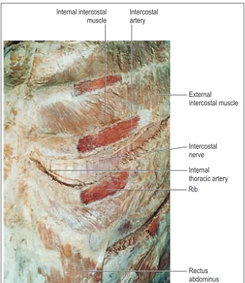
intercostal nerve and artery is highlighted on the lower edge of one rib[1]. . . 4 Figure 1.3 This picture shows a segement of intercostal neurovascular bundle that was
dissected from a 20 kg pig during one of the experiments related to this work. Even in small pigs, the neurovascular bundle is large enough to be easily felt and seen during surgery. . . 5 Figure 1.4 (A)De Quervain chest retractor, 1913.(B)Lilienthal chest retractor, 1917.(C)
Finochietto chest retractor, 1936[8]. . . 7 Figure 1.5 (A)Heartport retractor with articulating arms 1999[18].(B)Delacroix-Chevalier
retractor with angled blades, 2010[16].(C)Physcient retractor with motorized opening, 2007[14].(D)Rib retractor with wound-retractor (Alexis O-Ring, Ap-plied Medical), 2012[19]. . . 10
Figure 2.1 This figure depicts nerve function results after removal of a standard metal rib retractor[54]. The two nerves nearest the incision experienced complete conduction blocks in nearly every patient. . . 16 Figure 2.2 This figures shows the number of injured nerves that were detected after
retrac-tor removal and incision space closure in thoracotomy and thoracolaparotomy surgeries for 33 patients[55]. . . 17 Figure 2.3 This figure on the left shows CT scan of a 60 year old woman’s chest 10 years
after a thoracotomy with a standard retractor. The arrows indicate the location of two ribs fractures caused by the retractor[48]. The right of the figure displays the placement and orientation of the rib retractor. . . 19
Figure 3.1 (A)This is an image of a thoracic paravertebral block injection that is used to prevent post-surgical pain in thoracotomy patients[69]. The injection occurs be-fore the surgery while the patient is awake.(B)This is an image of an intercostal nerve block being performed before the surgery[69]. . . 22 Figure 3.2 This figure summarizes the muscle and nerve sparing technique. On the left a
cautery device is shown harvesting the intercostal muscle and nerve away from the inferior edge of the upper rib[44]. On the right, a retractor is placed directly on the rib while the intercostal muscle and tissue flap dangles below to avoid being crushed[51]. . . 24 Figure 3.3 This figure demonstrates the intracostal suture method. On the left, a surgeon
(without cutting) the ICNBs by moving them above and below the window and found that this rib resection-nerve preserving method reduced patient pain significantly[74]. . . 27 Figure 3.5 The top right image shows the flat bladed retractor used in the sternal force
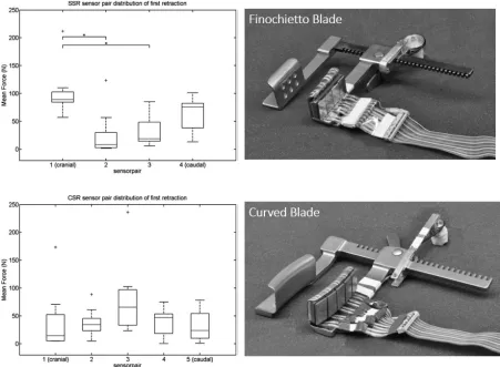
distribution study and the top left bar plot shows its mean forces recorded at the 5 segements along its length. The bottom right image shows the curved bladed retractor used in the sternal force distribution study and the bottom left bar plot shows its mean forces recorded at the 5 segments along its length[77]. . . . 29 Figure 3.6 The data on the left shows the average total retraction force for the instrumented
and standard retractors in the sheep thoracotomy study[15]. The picture on the right shows the force-feedback instrumented retractor being used to perform a sternotomy on a sheep[14]. . . 31
Figure 4.1 This figure depicts the primary inputs that led to the formal statement of the clinical need. This need statement, developed over 3 months, provided the framework from which the idea to develop a new retraction device arose. . . 35 Figure 4.2 This figure depicts the early designs of the force-distributing retractor blade. A
standard retractor frame arm(A)could receive a retractor blade(B)designed to soften impact on the intercostal nerve. The final blade concept incorporated the principle behind a car windshield wiper(C)which is designed to maximize contact area on a window of any curvature (drawings by Drew Brisley). . . 38 Figure 4.3 This figure depicts theExperimental concept(on right) which arose from the
need statement. The Finochietto blade (on left) does not match the radius of curvature of the ribs and this results in the application of excessive pressure to the ribs on both ends of the blade. The Experimental blade adapts to the unique shape of each patient’s rib to equalize pressure distribution during retraction. . 39 Figure 4.4 This figure shows all of the forces exerted on the retractor and ribs during
retraction. The goal was to design a retractor blade that matched the flexural rigidity of the rib to achieve maximum contact area. A reduction in the forces applied by the ends of a Finochietto blade (G31 in figure) would make the device a lot safer for patient tissue[95]. . . 41 Figure 4.5 The nerve on the bottom of the caudal rib will be directly exposed to contact
with the blade and will experience compression. All points on the rib below the elastic curve experience compression. The points on the caudal rib above the elastic curve will experience tension. The novel retractor blade was designed to match the radius of curvature of the elastic curve to increase contact area and distribute pressure. Blades 1 and 2 each apply equal and opposite forces for F1 and F2. If blade 1 is applying F1=200 N of force, blade 2 is applying F2= -F1=-200 N of force in the opposite direction and the total retraction force for
Figure 4.6 This figure shows a CT scan of an adult’s 8th rib[97]on the left and the elliptical geometric approximation on the right that was used to calculated the rib’s area moment of inertia. . . 44 Figure 4.7 This figure depicts the flexural rigidities that could be obtained by varying the
blade material and height between 1 and 4 mm. The lower 0.13 Pa·m4estimate
for human rib cortical bone rigidity is shown as a dotted line. The average and high estimates (not shown) for human rib cortical bone rigidity are 1.72 and 6.72 Pa·m4respectively. The 5.45 Pa·m4rigidity for the CPVC-4120 Pipe is also
Figure 5.2 This figure depicts the female cylindrical socket mechanism. These sockets were designed to allow the blades to rotate 360◦around the z-axis.(A)The sockets were made of stainless steel and were tig welded to the end of the retractor arms.(B)The height of the experimental retractor arm was 17.00 mm. Both retractor arms were equipped with female cylindrical sockets to receive and secure experimental blades.(C)The center-to-center distance between the sockets was 19.90 mm.(D)The perpendicular distance between the farthest edges of the cylinders was 34.00 mm.(E)The outer diameter of each female socket was 15.85 mm. The inner diameter was 12.00 mm.(F)The length of the socket window was 12.00 mm.(G)The height of the socket was 4.50 mm.(H) Each socket extended 22.00 mm from the surface of the retractor arm. . . 54 Figure 5.3 (A)The alumium sheet was cut to cover the fenestrated window and retraction
surfaces of the original Finochietto blade. The sheet extended to the bade of the curved lip but did not make contact with it. This size of the flat surface area allowed up to 10 force sensors to be placed in a rectangular array along the length of the blade. These blades were not permitted to rotate around the z-axis. (B) The width of the blade with the sheet attached was 35.50 mm.(C)The length of the blade was 64.00 mm.(D)The vertical back wall had a height of 28.50 mm.(E)The Finochietto retractor arm had a height of 17.00 mm; equal to the Experimental retractor arm height.(F)In the Side View, the lip-to-lip distance was 25.40 mm.(G)Each lip had a height of 12.00 mm.(H)The thickness of the aluminum sheet was 3.90 mm.(I)The thickness of the original Finochietto blade was 3.50 mm.(J)With the addition of the aluminum sheet, the minimum distance between the tissue engaging surfaces was 11.50 mm. . . 55 Figure 5.4 (A)The potentiometer wheel was attached to the head of the non-moving
retrac-tor using acrylic and two #6 screws.(B)The leads of the potentiometer could be reached via a 10 pin header.(C)Two lines were attached to the pulley wheel and provided torque in opposing directions. When the moving arm of the retractor advanced down the frame, the extension spring(D)provided force to keep all lines taught. Both the spring and tension lines were attached to the base of the moving acrylic box(E). The width of the box(F)was 36 mm. The total length of the box(G)was 17.0 cm.(H)Screws could be tightened to provide correct neutral tension on the pulley lines prior to experiments. The thickness(I)of the acrlic box was 20.5 mm. In the Inside View, the anchoring aluminum rod(J)can be seen with the lines passing through guiding holes that lead the lines to the tightening screws. . . 57 Figure 5.5 The line(A)applied a torque on the potentiometer wheel as the moving-arm
setup that was used in this work in the case of a Finochietto blade experiment. As mentioned previously, all force measurements took place on a single blade of each retractor (Blade 2) nearest the base of the frame rack. A 3.90 mm thick aluminum plate(A)was placed on top of the original Finochietto blade with epoxy. A single layer of double-sided adhesive tape (3M, MMM136)(B)held a laminate sheet (0.1 mm thick) holding the FlexiForce®A201-100lbs. sensors(C)
to the face of the retractor blade. The sensors were held directly to the laminate sheet using a spray adhesive (3M, Super 77). The pistons(D)were laser cut into 1.5 mm thick, 9.2 mm diameter disks that applied all the force directly to the sensors. The pistons were permanently attached to the sensing area of the force sensors using a spray adhesive. Rectangular aluminum bridges(E)with thickness 1.95 mm transferred the forces to the pistons and were attached to the pistons with cyanoacrylate adhesive (3M, CA40H). The aluminum bridges directly interfaced with the simulated ribs (or tissues) to generate displacement during retraction. The total height of the force sensor piston-bridge setup was 3.65 mm. . . 59 Figure 5.7 This figure depicts the geometry and arrangement of the 2x5 force sensor arrays
for both types of retractor blades. The Finochietto blade had a larger sensing area than the Experimental blade but both types had the same number of sensors. The numbers 1-10 on the top views of the aluminum bridges indicate the locations of each of the ten force sensors below the bridges. The width(A) of each Finochietto bridge was 12.5 mm. The height(B)of each Finochietto bridge was 36.0 mm. The width(C)of each Experimental bridge was also 12.5 mm and its height(D)was 25.00 mm. The center-to-center distance(E)of the Finochietto sensing areas was 26.5 mm. Experimental center-to-center distance was 15.5 mm. The underside of the arrays shows the laminate sheet(G)that held the sensors in their rectangular configuration. This sheet was placed directly on top of the retractor blade surface. The sensor leads were bundled with high tack tape (Gorilla TapeTM) and lead away from the blade area. . . 60 Figure 5.8 This figure shows the force sensor setup installed on the Finochietto retractor
blade. The orientation of the numbered sensors (1-5) with respect to the blade was the same for the Experimental retractor. Before this setup was used on animal tissue, the blade and sensors were covered in plastic foil to keep the setup dry. . . 61 Figure 5.9 This figure shows the Finochietto force sensor calibration over three trials. The
Figure 5.10 This figure shows the Experimental force sensor calibration over three trials. The sensor numbers correspond to the sensors labeled in Fig. 5.7. The error bars representing standard deviations can be seen to be very small. No linear relationship between voltage output and weight input had an R2value less than 0.99. . . 64 Figure 5.11 This figures shows the linear voltage output from the potentiometers during
blade displacement. Both potentiometers measured 0V with 0 mm displace-ment. The equations for Displacement D (mm) as a function of potentiometer voltage V (Volts) were Df =20.932·V and De =22.022·V for the Finochietto and Experimental retractors respectively. No linear relationship between voltage output and displacement had an R2value less than 0.99. . . 65
Figure 5.12 This figure depicts the complete data collection system that was used in this work to record both retractor blade forces and displacement. All the voltage output equations for the circuit components are shown. Each force sensor had an identical, but individual signal conditioning circuit. . . 66 Figure 5.13 This figure shows the constructed electronic circuit for recording signals from
the retractor sensors. The PCB board was secured in a laser cut acrylic box to protect the circuit during experiments.(A)10kΩsingle-turn potentiometer.(B) TL7600 DC Voltage Converter.(C)LM337 Negative Adjustable Voltage Regula-tor.(D)Three TLV-2464 Quad-package Operational Amplifiers.(E)Connection header for the 10 FlexiForce®A201-100lbs. sensors.(F)Two 2-pin PCB Screw Terminals for the Displacement Circuit Potentiometers.(G)Wires passing the 10 amplified force sensor signals to the NI-DAQ-6255. . . 68 Figure 5.14 This figures show the constructed electronic circuit connected to the NI USB
DAQ-6255. . . 69 Figure 5.15 Fujifilm Prescale®Medium (MS) is a single sheet pressure indicating film. When
pressure is applied to the film, micro capsules in the color-forming layer burst and release their contained material onto the color-developing layer. The micro capsules have a range a sizes that only burst when subject to a distinct amount of pressure. The color-developing layer turns the micro capsule material a magenta color instantaneously and their density of the magenta color is nearly proportional to the amount of pressure applied on the film in that particular area[132]. . . 69 Figure 5.16 This is an image showing how the pressure film was installed on the retractor
blades before testing on the pipe benchtop model of the ribs. The film was always placed polyester (shiny) side face down on the retractor blade surface for each trial. . . 70 Figure 5.17 This figures shows the CPVC pipe rib benchtop simulation model. Before each
applied. A video camera recorded the displacement d of a pipe as forces fdup to 50 lbs. were applied by an attached fish scale hook. Displacement measurements were taken using still images from video and ImageJ software. . . 72 Figure 5.19 This figure shows the results of the four cpvc pipe calibration trials
charac-terizing displacement as a function of applied force. Error bars represent the standard deviations. . . 73 Figure 5.20 This figure shows the calibration curve used to convert pixel values to pressure
values. Both curves were fit with third degree polynomials. The calibration was done for the extended exposure method of applying pressure to the film. . . 75 Figure 5.21 This figure shows an example of a pressure film scan from a film used on
Finochi-etto blade. The original RBG color scan in on the left and the resulting grayscale image is on the right. . . 76 Figure 5.22 This figure shows an example of a histogram analysis of the entire pressure film
scan from a film used on Finochietto blade. All calculated statistics appear in the box in the figure. . . 77 Figure 5.23 This figure shows an example of the pressure map of a film used on Finochietto
blade. . . 78 Figure 5.24 This figure shows an example of a Finochietto pressure-area histogram for each
of the 5 segmented images. The center image (segment 3) is the center of the retractor blade. . . 79 Figure 5.25 This figure shows the Labview block diagram of the force sensor and
displace-ment data collection program. . . 82 Figure 5.26 This figure shows the start and end of one of three example retraction cycles.
The force statistics were calculated over only the retraction cycle times. . . 83
Figure 6.1 CAD drawings for the Durus White 4 mm thickness retractor blade. All units are in millimeters. . . 87 Figure 6.2 (A)Durus White 4 mm CAD model in SolidWorks.(B)FEA static load simulation
with average thoracotomy force applied along center of blade.(C)Finochietto blade CAD model in Solidworks.(D)FEA static load simulation with same force applied along center of blade. The purple arrows indicated the application of the static force over a surface or edge. . . 89 Figure 6.3 Factor of safety (FOS) comparison between the Finochietto blade and Durus
White 4 mm blade at forces relevant to thoracotomy. The horizontal line is through FOS=1. . . 89 Figure 6.4 The left image shows the 3D printed Durus White 4 mm thick blade prototype.
Figure 6.5 The left image shows a top view of the Durus White 4 mm blades deflecting into the space between the pipes. The retractor arms in this image are 50 mm apart while the experimental blades are only 20 mm apart; a distance at which the blades were extremely likely to break. The right image shows a side view of the blades deflecting 14◦from their neutral (unloaded) vertical position. . . 92 Figure 6.6 This figure shows a bar graph of the contact area distribution along each blade’s
length during the pressure film experiment. All error bars show the standard deviation of the mean. . . 93 Figure 6.7 This bar plot shows the mean 95% percentile pressures at each segment along
the Finochietto and 4 mm Durus White blades. The pressure values for the Finochietto were likely greater than the recorded values which exceeded the sat-uration limit of the pressure film. All error bars represent the standard deviation of the mean. . . 94 Figure 6.8 This box plot shows the mean pressure distributions at each segment on the
Finochietto and 4 mm Durus White blade. . . 95 Figure 6.9 This bar plot shows the mean 95% percentile maximum force applied on 5
seg-ments of the Finochietto and 4 mm Durus White blades. All error bars represent the standard deviation of the mean. . . 96 Figure 6.10 This box plot shows the distribution of mean force values at each segment for
the Finochietto and 4 mm Durus White blades. . . 97
Figure 7.1 CAD drawings for the 3 mm ABS thick titanium pin retractor blade. All units are in millimeters. . . 101 Figure 7.2 This plot compares the factor of safety (FOS) between the 4.5 diameter titanium
rod and the Finochietto blade. The titanium rod was designed to provide nearly equivalent FOS values for all applied loads. . . 102 Figure 7.3 This plot compares the factor safety between the 3 mm ABS Titanium blade
and the Finochietto blade at forces relevant to thoracotomy. The switch to a titanium rod and a more rigid plastic blade material increased the overall FOS values to nearly match the Finochietto under higher loads. . . 103 Figure 7.4 This figure shows how the experimental blades were installed onto the titanium
pin adapters. A single square key peg(A)(2 mm x2 mm x1 mm) slid down a notched tunnel(B)on the blades. The key peg locked the blades onto the titanium post once it reach the end of the tunnel and the blade was rotated 180◦around the z-axis. The base of the titanium adapter was secured to the arm of the retractor with a 3/16” bolt, washer, and allen socket nut(C). The center-to-center minimum distance(D)between the titanium rods was 20 mm. The length(E)of the titanium pin was 26 mm. The diameter(F)of the titanium adapter base was 12 mm. The height(G)of the adapter was 22 mm. The diameter (H)of the titanium rod was 4.50 mm. The distance from the edge of the key peg (I)to the end of the rod was 3 mm. The length(J)of the square peg was 2 mm and the distance(K)of the edge of the peg to the base of the adapter was 21 mm. 104 Figure 7.5 This image shows the 3 mm ABS Titanium blade that was printed on a Stratasys
Figure 7.7 This bar plot compares the mean 95% percentile maximum force at each seg-ment on the Finochietto, 4 mm Durus White, and 3 mm ABS Titanium blades. . 107 Figure 7.8 This box plot compares the distribution of the mean pressure for each blade
segment in the Finochietto, 4 mm Durus White, and 3 mm ABS Titanium blades.108 Figure 7.9 This bar plot compares the mean 95% percentile maximum force on the
seg-ments of the Finochietto, 4 mm Durus White, and 3 mm ABS Titanium blades. . 109 Figure 7.10 This box plot compares the distribution of the mean forces on the segments of
the Finocietto, 4 mm Durus White, and 3 mm ABS Titanium blades. . . 109
Figure 8.1 CAD drawings for the Durus White 3 mm thick titanium pin retractor blade. All units are in millimeters. . . 113 Figure 8.2 This plot compares the factor of safety (FOS) between the Durus White 4 mm
blade, ABS 3 mm Titanium blade, and Durus White 4 mm Titanium blade. The switch to the Durus White from ABS plastic on the titanium rod slightly decreased the FOS values for all applied loads. . . 114 Figure 8.3 The left image shows the Durus White 3 mm Titanium blade printed on the
Stratasys Objet30 Pro printer with layer thickness of 28 microns. The right image shows the blades installed on the titanium rods in the closed retractor position. 115 Figure 8.4 This bar plots compares the mean contact area for each of the segments of the
Finochietto, 4 mm Durus White, 3 mm ABS Titanium, and 3 mm Durus White Titanium blades. . . 116 Figure 8.5 This bar plot compares the mean 95% percentile maximum force at each
seg-ment on the Finochietto, 4 mm Durus White, 3 mm ABS Titanium, and 3 mm Durus White Titanium blades. . . 116 Figure 8.6 This box plot compares the distribution of the mean pressure for each blade
segment in the Finochietto, 4 mm Durus White, 3 mm ABS Titanium blades, and 3 mm Durus White blades. . . 117 Figure 8.7 This bar plot compares the mean 95% percentile maximum force on the
seg-ments of the Finochietto, 4 mm Durus White, 3 mm ABS Titanium blades, and 3 mm Durus White Titan. blades. . . 118 Figure 8.8 This box plot compares the distribution of the mean forces on the segments
of the Finocietto, 4 mm Durus White, 3 mm ABS Titanium blades, and 3 mm Durus White blades. . . 118 Figure 8.9 This bar plot shows the mean total force required for the blades to open the
pipe setup to 20 mm. The 4 mm Durus White blade was not able to provide the same amount of force as the other blade designs because of its precarious plastic connection mechanism. . . 119 Figure 8.10 This bar plot compares the mean total force required to open the blades to 20
Figure 9.1 The image on the left shows the experimental blades retracted at approximately 8 cm in a thoracotomy performed on a young 20 kg (45 lbs.) pig. One blade can be seen matching the radius of curvature of the retracted rib. The right image shows the blades after removal from the pig’s thorax. Each blade applied similar forces to the two ribs and experienced permanent deformation due to the small
radius of curvature of the pig’s ribs. . . 123
Figure 9.2 The image on the left shows a Finochietto retraction being performed on a young 20 kg (45 lbs.) pig. The lung can be seen in the opened space. During the second Finochietto trial, there was a complete rib fracture at the 8 cm opening size. The right image shows the fractured rib which occurred on the dorsal end of the caudal rib. . . 124
Figure 9.3 The top plot shows Finochietto force segment data during retraction to 8 cm at which point a rib fractured (35 lbs. total force). The bottom plot shows 3 mm Durus White Titanium segment force data during retraction to 10 cm (up to 63 lbs. total force). . . 125
Figure A.1 This stack of plots shows all recorded retraction sequences for all types of re-tractor blades. . . 149
Figure A.2 Scanned image of all Finochietto blade pressure film trials. . . 150
Figure A.3 Scanned Image of all 4 mm Durus White blade pressure film trials. . . 151
Figure A.4 Scanned image of all 3 mm ABS Titanium blade pressure film trials. . . 152
1
INTRODUCTION
1.1
Anatomy of the Thorax
The thorax contains the heart, lungs, esophagus, trachea, aorta, and other vital vessels necessary for transporting blood throughout the body. These vital organs and vessels are protected by the rigid
bony structure of the thorax. The cavity of the human thorax is protected by 12 thoracic vertebra on the posterior side, the sternum on the anterior side, and 12 pairs of ribs on either side (Fig. 1.1). The
diaphragm defines the caudal boundary and the base of the neck defines the cranial boundary of
the thorax. The ribs pairs are numbered 1 through 12 starting on the cranial side. On the anterior side, the first 7 pairs of ribs are directly joined to the sternum with costal cartilage. Each of the 12
pairs of ribs are joined to the spine on the posterior side with costal cartilage. The 8th, 9th, and 10th
pairs of ribs are connected to the ribs above with costal cartilage and the 11thand 12thpairs of ribs are floating ribs that have no connection to any tissue structures on the anterior side[1]. The
costal cartilage provides a flexible anchor for the ribs that allow the thorax to expand and contract
during breathing and to absorb and disperse energy from physical impacts. The sternum is a flat bone segment that serves as the front anchor of the thorax’s anterior wall for the first 7 pairs of ribs.
The sternum is divided into 3 segments: the manubrium (superior), body, and the smaller xiphoid
1.1. ANATOMY OF THE THORAX CHAPTER 1. INTRODUCTION
Figure 1.1This schematic illustration of the human thorax depicts the thoracic walls that protect the
Contraction and relaxation of the diaphragm and intercostal muscles allows inhalation and exhalation to occur. When the diaphragm relaxes during inhalation, the intercostal muscles of the
upper rib contract to stiffen the thoracic walls and prevent their inward collapse[3]. The lower
intercostal muscles and diaphragm contract during exhalation to assist in pushing air out of the lungs[3]. There are 3 layers of intercostal muscle between each rib called the external, internal, and
innermost intercostal muscle. A neurovascular bundle lies between the internal and innermost
intercostal muscle layers[1]. The ribs have a lower groove in their elliptical shape that protects the neurovascular bundle on the rib’s posterior side. The neurovascular bundle, which lies on the lower
border of each rib, contains the intercostal vain, artery, and nerve in top to bottom arrangement.
The intercostal nerves branch from the thoracic spinal segments T1-T11 and travel along the length of the rib to innervate the intercostal muscles and to provide sensory information back to the central
nervous system (Fig. 1.2,Fig. 1.3). Most anatomy textbooks depict a single primary neurovascular
bundle lying on the lower edge of each rib, however a few textbooks and articles indicate the presence of a collateral branch of intercostal neurovascular bundle that runs along the top edge of each rib [4].
Inside the thoracic wall, the interior of the thorax is divided in the left and right pleural cavities and the mediastinum[5]. The mediastinum contains all of the the thoracic viscera and lies between
the two separate pleural cavities. Each pleural cavity is defined by an inner pleural layer and an outer parietal pleural layer. The space between these two layers is fluid filled and called a pleural
cavity. The pleural layers on each side of the thorax form a membrane that lines the thorax and
contains the lungs. The pleura extends from about 3 cm above the medial part of the clavical down to the midclavicular line of the 8thrib[1].
1.2
Thoracic Retractors
Thoracic surgery has a history that goes back several thousand years, however most of the techno-logical developments that have made modern sugery possible have occured in the last 150 years.
Surgical instruments are known to have existed around over 12,000 years ago and the Indian
surgeon-healer known as Sushruta provided the first description of more than 120 surgical instruments in approximately 500 B.C.[6]. Descriptions specific to thoracic surgery date back to the time of
Hip-pocates (400 B.C.) when techniques for managing empyema were being developed[7]. Empyema occured when a collection of pus filled the pleural cavity. Whenever surgeons during the time of
Hippocrates entered the pleural cavity to remove the pus, the lungs collapsed (open pneumothorax),
1.2. THORACIC RETRACTORS CHAPTER 1. INTRODUCTION
anterior abdominal wall as well.
✪
Segments of skin
supplied by the intercostal nerves are common sites of
vesicles in Herpes zoster, a viral infection affecting the spinal
nerve ganglia spreading through the intercostal nerves.
The internal thoracic artery, a major artery on the anterior
aspect of the chest wall, is a branch of the subclavian artery
and it descends vertically downwards lying about 1cm
lateral to the sternum. In the sixth intercostal space it divides
into its two terminal branches, the musculophrenic and
superior epigastric arteries, the latter entering the anterior
abdominal wall by passing through the diaphragm
The anterior intercostal arteries are branches of the
internal thoracic artery or those of its musculophrenic
branch. Most of the posterior intercostal arteries are derived
from the descending thoracic aorta.
✪
Anastomoses
between the anterior and posterior intercostal arteries are
important collateral channels for circulation in cases of
obstruction to the blood fl ow in the aorta anywhere beyond
the origin of the left subclavian artery.
The thoracic cavity, lungs and pleura
The thoracic cavity contains on either side the right and left
lungs surrounded by the pleural cavities and the
mediastinum in between.
The lungs and pleural cavities
See Figures 3.4–3.11. The right lung is subdivided into
superior, middle and inferior lobes by an oblique fissure and
a horizontal fissure (Figs 3.4 and 3.5). The left lung usually
has only two lobes, a superior and an inferior with an
oblique fissure in between. Each lung has an apex which
extends about 3cm above the clavicle into the neck, a costal
surface, a mediastinal surface and a base or diaphragmatic
Suprasternal notch
Clavicle
Manubrium sternum
Sternal angle
2nd costal cartilage
Body of sternum
Xiphisternum
7th costal cartilage
10th costal cartilage
Fig. 3.2
Bony thoracic cage.
Internal intercostal muscle Intercostal nerve External intercostal muscle Intercostal artery Rib Internal thoracic artery Rectus abdominus
Fig. 3.3
Intercostal spaces (left side).
Clinical box 3.2
Thoracocentesis, insertion of a chest drain
Insertion of a chest tube into the pleural cavity is
required to remove large amounts of serous fl uid, blood,
pus or air. The site of insertion of the tube is usually at
the 5th intercostal space just anterior to the midaxillary
line on the affected side. This site will avoid the tube
going through the pectoral muscles which lie more
anteriorly and will avoid possible damage of liver (right
side) and spleen (left side) which are overlapped by the
pleural cavity more inferiorly (see Clinical box 3.3).
Nerve to serratus anterior lies at the level of insertion of
the tube and may be damaged occasionally, causing
winging of the scapula (see Clinical box 2.1).
A needle thoracocentesis done in a critically ill patient
with tension pneumothorax may be life saving. An over
the needle catheter is inserted into the pleural cavity on
the side of the tension pneumothorax through the
second intercostal space in the midclavicular line.
Insertion medial to the midclavicular line has a potential
danger of damaging the great vessels in the
mediastinum.
The needle or chest drain is always inserted superior
to the rib (lower part of the intercostal space) to avoid
damaging the neurovascular bundle. Damage of the
intercostal nerve will cause neuritis and pain (neuralgia)
and puncture of the vessels may result in bleeding into
the pleural cavity (haemothorax).
The parietal pleura, the periosteum and other
structures in the area of needle insertion and chest drain
have rich innervation and hence a good local
anaesthesia is required for procedures mentioned above.
52
HUMAN ANATOMY
Figure 1.2This figure shows a picture of the intercostal spaces in human cadaver. The intercostal nerve
and artery is highlighted on the lower edge of one rib[1].
1.2. THORACIC RETRACTORS CHAPTER 1. INTRODUCTION
described until 500 years later by Galen[7].
In the 16thcentury Vesalius used endotracheal insufflation to expand the lungs of animals during
exposure of the organs in the thorax[8]. Near the end of the 18thcentury, Curry used endotracheal
intubation for resuscitation of drowning victims and throughout the 1800s many incremental tech-niques were developed for providing positive and negative pressure to the lungs through tracheal
intubation[7]. O’Dwyer implemented a foot operated bellows to connect to an endotracheal tube
to ventilate the lungs and this method became the standard technique for both artificial respiration and anesthetic delivery by the beginning of the 20thcentury[7].
Once the internal organs could be safely accessed and ventilation could be maintained, surgeons
worked on techniques for optimizing the approach and exposure of the internal thoracic organs. The two primary techniques for gaining access to the thoracic cavity in the 20thcentury were
thora-cotomy and sternotomy and both of these techniques are still widely used today. Thoracotomies and
sternotomies are considered open procedures and they are used to perform lung resections, heart valve repairs and replacements, removal of spinal tumors, and treatment of cancerous esophageal
tissue to name a few. Insternotomy, the patient’s sternum is cut into partial segments or completely split to open up the patient’s chest for easy visualization and access of target organs. The sternotomy provides maximum visualization of the thoracic cavity and is used often used for lung and heart
transplants or for complex compound thoracic surgeries.
In athoracotomy, the surgeon accesses the internal organs of the thorax by separating a space for visualization between the patient’s ribs. The surgeon has to carefully select the correct intercostal
space to open for a thoracotomy before making an S-shaped incision extending from the tip of the scapula and extending towards the anterior midline using electro-cautery[7]. The center of the
incision line can be more anterior or postlateral depending on the organs that need to be accessed.
The surgeon then uses electrocautery to cut through the subcutaneous layer of fat before reaching and dividing the latissimus dorsi muscle. Various methods can be used to go through the intercostal
muscles but the surgeon should always take care to avoid cutting near the bottom of ribs where the
neurovascular bundle is located. The length of muscle incision can be different than the length of the outer skin incision. Once the intercostal muscle and underlying pleura have been passed, the
surgeon then installs a thoracic retractor to hold the opening during the course of the entire surgery.
1.2.1 Origin of the Thoracic Retractor
At the beginning of the 20thcentury, surgeons in Europe began to design and use hand-operated
devices to open the chest. These thoracic retractors needed to provide large openings (up to 20
adopted was developed by the Swiss surgeon Fritz De Quervain (Fig. 1.4)[8]. This all-metal retractor was opened by turning a screw mechanism that moved two pivoting arms with attached pivoting
blades. Surgeons complained of the large blades on this retractor and in 1917, Lilienthal presented
a new retractor design. Lilienthal’s retractor had interchangeable blades and was opened by turning a screw that moved one retractor arm along its length.
The early hinged retractors had limitations in the size of the opening they could create so
surgeons began to design retractors that were not-limited by the opening mechanism. Surgeons such as Theodore Tuffier in around 1920, began to use thoracic retractors that had two arms attached
to a transverse rack[8]. One of the arms, was allowed to move along the rack with a butterfly screw
mechanism that was turned by hand. This design allowed the size of openings to only be limited by the length of the transverse rack, however it also had its technical shortcomings. The locking
mechanism required an additional step and there was little mechanical advantage with the
thumb-screw applying such large forces. Despite these limitations, modified versions of the Tuffier retractor are still in use today for performing mini-thoracotomies.
Figure 1.4 (A)De Quervain chest retractor, 1913.(B)Lilienthal chest retractor, 1917.(C)Finochietto chest
retractor, 1936[8].
The biggest breakthrough in thoracic retractor design came with the introduction of the Finochi-etto retractorin 1936 (Fig. 1.4). Enrique Finochietto, an innovative Argentinian surgeon, imple-mented a rack-and-pinion opening mechanism that moved one of the retractor arms along the
re-1.2. THORACIC RETRACTORS CHAPTER 1. INTRODUCTION
tractors because it did not allow the arms to collapse unless the surgeon reversed the direction of the hand-held lever. Finochietto saw the rack-and-pinion mechanism used for another
applica-tion while operating in France during World War I and used it for his retractor upon his return to
Argentina after the war[6],[8]. The lever helped surgeons apply significant spreading forces to the ribs and this was the most ergonomical design ever offered for a retractor. The Finochietto retractor
could be easily disassembled for sterilization and required very little maintenance over the course
of many surgeries. Finochietto added fenestrated blades to his retractor to help secure the blades in the tissue. When significant spreading force was applied to the soft tissue surrounding the ribs, this
tissue would protrude through the fenestration to prevent the blades from slipping out of place. The
Finochietto retractor was universally adopted at the time of its introduction and is still widely used in hospitals around the world today, appearing in different sizes for adults and children[9]. Most
retractor companies offer Finochietto retractors with various size frames and blades to allow the
retractors to be used on a variety of patient sizes including large and small animals. The Finochietto retractor’s simplicity and reliability have allowed it to remain the standard retractor for thoracic
surgeries for over seven decades.
1.2.2 Evolution in Retractors
The Finochietto retractor that is used today is mostly identical to the retractor that was introduced
in the 1930s. Since the introduction of the Finochietto retractor, medical device companies have
focused primarily on expanding the visual field of the opening and giving surgeons more control of the retractor’s opening mechanism[10],[11]. In the last two decades, there have been a few
technological improvements to the standard Finochietto design.
In 1999, Heartport Inc. (Redwood City, CA) filed a patent for a thoracic retractor that had artic-ulating retractor arms, interchangable blades, and connections for attachment of additional soft
tissue retractors[12](Fig. 1.5). This retractor had hinged arms that could be bent into the thoracic
cavity to assist with stabilization of the blades on the ribs. Like the De Quervain retractor of 1913, the blades on the Heartport retractor could pivot to maintain contact with moving ribs. This pivoting
feature is still being emphasized by modern designs today[13]. In addition, the retractor frame had
a foot stabilization that could be used to lift one side of the retractor from the plane of the patient’s tissues. This feature helped surgeons gain a larger field of view into the thorax of the patient.
In 2007, Physcient (Durham, NC) developed and tested a prototype for an electronic retractor (Fig. 1.5) that was designed to reduce tissue trauma to the patient during opening[14]. The surgeon
installed this retractor (discussed in Chapter 3) between the ribs and then a software program
Multiple pivoting blades were used to increase visualization along the length of the lateral incision, but the key innovation was the slow and controlled opening of the thorax. The slow opening of
the ribs allowed the soft tissue and ribs to experience cyclical stress and relaxation periods that
prevented tissue damage. The retractor took about 10 minutes to complete the retraction to 7.5 cm in published animal studies[14],[15].
The Navarro retractor (Delacroix-Chevalier, 2010) had pivoting blades that acted as a soft and
hard tissue retractor. The blade was angled at its connection to the retractor arms to provide a conical field of view into the thorax. At a 5 cm retraction, the company claimed to double the size
of the field of view[16]. In addition, like many other current retractors, the metal Navarro blades
were curved with a fixed radius of curvature to prevent damage to the ribs. The installation of this retractor in the thorax is not as easy as other retractors as 2 people are required to attach the tissue
installed-blades to the arms of the retractor before opening. In addition, its arms are hinged and
curved to ensure that that blades reach the proper depth into the thorax to reach the ribs.
A popular technique that has arisen recently is the combination use of both a soft tissue and
rib retractor for both open and minimally invasive chest operations[17]. Surgeons can install a
wound-retractor, such as the Alexis O-ring (Applied Medical), into the incision before installation of a metal rib spreader on top of it to apply the spreading force. Some surgeons prefer to use this
technique to keep the incision site clean and to fully retract soft tissue at all angles around the opening into the thorax.
As can be seen with these recent examples with exception of the Physcient retractor which never
made it to market, most innovations in the thoracic retractor space have addressed increasing the field of view and increasing the ease of use for the surgeon. Few devices have attempted to improve
the experience for the patients.
1.3
Relevant Surgical Procedures
It is estimated that between 150,000 and 350,000 thoracotomies and 500,000 sternotomies are
performed each year in the United States[20]. This estimate was made by compiling all relevant
ICD-9-CM Procedure Codes reported in the Healthcare Cost and Utilization Project (HCUP) database[20] using a procedure search method suggested by Kent et al.[21]. The standard thoracic retractor can
be used in either thoracotomy or sternotomy to separate the ribs or sternum. Most of the procedures where a thoracic retractor is used involve treating a diseased heart, lung, or arteries. Within the
last few decades, the less invasive thoracotomy approach has become the preferred method over
1.3. RELEVANT SURGICAL PROCEDURES CHAPTER 1. INTRODUCTION
Figure 1.5 (A)Heartport retractor with articulating arms 1999[18].(B)Delacroix-Chevalier retractor with
maintaining the direct access to critical organs and tissues in a variety of procedures such as heart and lung transplants, aortic valve replacements and repairs, mitral valve replacements or repairs,
lobectomies and lung resections, removal of spinal tumors, biopsies of the pleura, esophageal tumor
removals, and coronary artery bypass procedures (CABG).
1.4
Current Trends
Two new approaches to accessing the thorax have emerged more recently: the video-assisted thoras-copy (VATS) in the early1990s and the robotic VATS more recently[26]. Of these two techniques, VATS
is the most popular and is quickly becoming used across the United States as a primary method
of thoracic access in benign procedures[27],[28]. In a traditional VATs procedure, the surgeon makes one or more small incisions between different intercostal spaces. These incisions are used
as ports through which endoscopes, graspers, and other tools assist in the procedure. In a robotic
VATS, a surgeon performs the VATS surgery remotely with the Da Vinci®surgical robot (Intuitive Surgical, CA).The advantage for a patient undergoing a VATS procedure is that no rib spreading is
performed and the incisions are very small. This procedure has demonstrated lower postoperative
pain, better cosmetic results, and quicker recovery compared to sternotomy and thoracotomy These improvements had led to increased use of VATS around hospitals in the U.S. over the last 10 years.
Despite an increase in the number of VATS procedures every year, it is estimated that as of 2011,
thoracotomy is still performed in about 74% of all surgical interventions for lung cancer worldwide [29],[30]. In a sample of 33,000 patients who underwent a lobectomy or segmentectomy between 2008 and 2010 across 6 U.S. states, nearly nearly two-thirds of the patients had thoracotomies while
one-third had VATS procedures[21]. In that study, only around 3% of the patients had a robotic procedure performed. Robotic VATS are performed very infrequently and in 2006, 1700 robotic
cardiac cases were performed, indicating that each Da Vinci®system only performed 7 cardiac
cases per year in the U.S.[31].
An interesting finding in that three year study by Kent et al.[21]that may be indicative of the
overall thoracotomy trend in the U.S. was that the number of thoracotomies performed performed
per year dropped by 10% from 2008 to 2010. While the number of thoracotomies performed in the U.S. decreases and the number of VATS increases, it is likely that the number of these two
ap-proaches performed per year will stabilize over time. The thoracotomy and VATS each has its unique advantages and weaknesses that a surgeon must consider for each case. The intercostal space is
usually 1 cm wide and it is difficult to remove tumors larger than 5 cm in diameter with a VATS
1.4. CURRENT TRENDS CHAPTER 1. INTRODUCTION
the cost of inducing more pain for the patient. The number of VATS procedures performed each year is rising significantly while thoracotomy procedures are performed in less numbers. However,
thoracotomy will not be completely replaced because there will always be a significant number of
2
THORACOTOMY PAIN
2.1
Post Thoracotomy Pain Syndrome (PTPS)
The biggest problem that patients deal with after thoracotomy is severe pain, both in acute and chronic form[34]. Thoracotomy is considered one of the most painful procedures that a person
can undergo with the post-surgical pain comparable to both amputation and mastectomy[35], [36]. In the week after a thoracotomy, the pain can be severe enough to prevent a patient from taking full breaths while recovering in the hospital[37]. If this happens the buildup of fluid in the
the patient’s lungs increases the risk of developing pneumonia[34]. Thoracotomy patients have reported experiencing long-term chronic pain months and years after their surgeries in a condition
that is calledPost-Thoracotomy Pain Syndrome (PTPS). The clinical definition for diagnosing PTPS, established by the International Association for the Study of Pain, is “pain that recurs or persists along a thoracotomy scar at least two months following the surgical procedure"[38]. PTPS
is believed to be a form of peripheral neuropathic pain where nerve roots or trunks are physically
damaged[39]. Damage done to the intercostal nerves during thoracotomy can be severe enough to cause total conduction blocks that lead to denervation and hyperalgesia (suprasensitization)[40].
Patients suffering with PTPS often describe the pain located along their incision site as “burning,"
2.2. PTPS CAUSES CHAPTER 2. THORACOTOMY PAIN
Numerous studies have tried to estimate the incidence of PTPS over the last 20 years while the problem of persistent pain after thoracotomy has been known for decades. The first official
diagnoses of PTPS was done by surgeons during World War II treating soldiers with chest wounds [34]. It estimated that the incidence of PTPS at 3 and 6 months is 57% and 47% respectively based on one comprehensive study that reviewed a large collection of available literature[41]. In about
5% of the patients with PTPS, the pain is so severe that the patient experiences physically disabling
pain[42]. Surgeons have tried numerous peroperative and postoperative measures to prevent PTPS but its incidence has not changed significantly since the 1990s[41].
2.2
PTPS Causes
2.2.1 Potential Factors
Surgeons have cited many sources for the cause of PTPS, but most agree that damage to the
inter-costal nerve is the primary cause[42]–[45]. In thoracotomy, surgical damage to the intercostal nerve and surrounding tissue can occur during the incision, retraction, closure of the incision, and healing
of the wound. Nerve regrowth can cause pain when the nerves regrow in abnormal directions after
being damaged in the surgery. Table 2.1 lists many of the potential causes of PTPS found in the literature.
2.2.2 Damage by Retractors
Thoracic retractors are directly responsible for some of the causes of PTPS. Although the devices have provided sufficient visualization to the diseased tissues for decades, a body of evidence has
accumulated linking metal thoracic retractors to nerve and rib damage.
2.2.2.0.1 Nerve Compression and Traction
In 2002, Rogers et al. published a key paper demonstrating the extent to which a retractor can
damage the intercostal nerve during thoracotomy[54]. The authors wanted to determine at what
point during a thoracotomy the intercostal nerve experienced the most damage, so they measured nerve conduction before and after entering the pleural space, after removal of the rib retractor, and
after intercostal space closure. In addition, nerve conduction was recorded at the same locations on the two ribs above and below the incision. Stimulator evoked nerve potentials at one end of
the intercostal nerve and bipolar recording needles on the other end of the nerve measured the
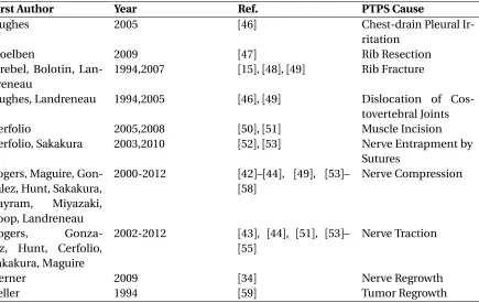
Table 2.1This tables lists many of the peroperative and postoperative causes of PTPS that are cited in the literature.
First Author Year Ref. PTPS Cause
Hughes 2005 [46] Chest-drain Pleural
Ir-ritation
Stoelben 2009 [47] Rib Resection
Strebel, Bolotin, Lan-dreneau
1994,2007 [15],[48],[49] Rib Fracture
Hughes, Landreneau 1994,2005 [46],[49] Dislocation of
Cos-tovertebral Joints
Cerfolio 2005,2008 [50],[51] Muscle Incision
Cerfolio, Sakakura 2003,2010 [52],[53] Nerve Entrapment by
Sutures Rogers, Maguire,
Gon-zalez, Hunt, Sakakura, Bayram, Miyazaki, Koop, Landreneau
2000-2012 [42]–[44], [49], [53]– [58]
Nerve Compression
Rogers,
Gonza-lez, Hunt, Cerfolio, Sakakura, Maguire
2002-2012 [43], [44], [51], [53]– [55]
Nerve Traction
Gerner 2009 [34] Nerve Regrowth
2.2. PTPS CAUSES CHAPTER 2. THORACOTOMY PAIN
between 7-17 cm on the patients.
Before the intercostal incision, all 12 patients had conducting nerves. After the intercostal
incision, 9 patients continued to have normal nerve conduction.
In all 12 patients tested, the nerve above the incision did not conduct at all after removing the retractor (Fig. 2.1). It was found that the nerve conduction block occurred at the distal level of the
retractor in 9 cases and there was a total conduction block in 3 cases. In the nerve below the incision,
there was a conduction block in 8 patients after removal of the retractor. The highest intercostal nerve (2 ribs above incision) had conduction block in 6 patients after removal of the retractor.
After closure of the intercostal space there was no further damage to the nerves. A last patient
had no spreading performed and had normal conduction all the way through to incision closure.
Figure 2.1This figure depicts nerve function results after removal of a standard metal rib retractor[54].
The two nerves nearest the incision experienced complete conduction blocks in nearly every patient.
This was the first study to objective demonstrate that nerve damage is done during thoraco-tomy. The results also showed that nerves under ribs above and below the incision experience
significant enough compression from the retractor to cause conduction blocks. The rib spreader
caused conduction blocks at the ends of the blade in every patient observed. The authors concluded that the retractor applied a direct compression force to the nearest exposed nerve and a traction
demonstrated the physical damage done to nerves by retractors but did not indicate how much pain it caused the patients after the surgery. An earlier study by Benedetti et al. in 1997 showed that
a lack of abdominal reflex ability after lateral thoractomy was associated with increased pain[60].
The authors in this earlier work observed abdominal muscles innervated by intercostal nerves. The combination of these studies suggests that retractors cause measurable physical damage to nerves
intraoperatively and there is subsequent pain associated with this damage after the surgery.
The 2002 Rogers study provided motivation for a follow-up study by MaGuire et al. in 2006[55]. In this follow-up study, the authors wanted to see if intraoperative nerve damage could predict long
term pain after thoracotomy. Nerve conduction was measured before and after retractor use across
several ribs as done in the Rogers study. The results again showed that retractors could immediately disrupt and damage the intercostal neurovascular bundle (Fig. 2.2). By the time closure was finished,
all 33 patients had at least one nerve experience a conduction block, with 5 patients experiencing
a complete conduction block. The other patients experienced discrete conduction blocks at the site of the retractor blades. Although the results of the study did not indicate that nerve damage
detected at the time of surgery lead to significant pain 3 months after surgery, the authors noted
that longer retractor times lead to complete nerve conduction blocks. The longer retractions (mean 141 minutes) stretched the nerves (traction) along the ribs compared to short retractions (mean 95
minutes) where conduction blocks occurred at the location of the retractor blades.
Figure 2.2This figures shows the number of injured nerves that were detected after retractor removal and


![Figure 1.5 (A) Heartport retractor with articulating arms 1999wound-retractor (Alexis O-Ring, Applied Medical), 2012 [18]](https://thumb-us.123doks.com/thumbv2/123dok_us/1325861.1165489/31.612.92.543.185.544/figure-heartport-retractor-articulating-retractor-alexis-applied-medical.webp)
![Figure 2.1 This figure depicts nerve function results after removal of a standard metal rib retractor [54].The two nerves nearest the incision experienced complete conduction blocks in nearly every patient.](https://thumb-us.123doks.com/thumbv2/123dok_us/1325861.1165489/37.612.99.529.303.517/function-standard-retractor-nearest-incision-experienced-complete-conduction.webp)
![Figure 2.2 This figures shows the number of injured nerves that were detected after retractor removal andincision space closure in thoracotomy and thoracolaparotomy surgeries for 33 patients [55].](https://thumb-us.123doks.com/thumbv2/123dok_us/1325861.1165489/38.612.153.474.429.631/gures-detected-retractor-andincision-thoracotomy-thoracolaparotomy-surgeries-patients.webp)
![Figure 3.2 This figure summarizes the muscle and nerve sparing technique. On the left a cautery device isshown harvesting the intercostal muscle and nerve away from the inferior edge of the upper rib [44]](https://thumb-us.123doks.com/thumbv2/123dok_us/1325861.1165489/45.612.91.543.263.498/figure-gure-summarizes-technique-isshown-harvesting-intercostal-inferior.webp)
![Figure 4.6 This figure shows a CT scan of an adult’s 8th rib [97] on the left and the elliptical geometricapproximation on the right that was used to calculated the rib’s area moment of inertia.](https://thumb-us.123doks.com/thumbv2/123dok_us/1325861.1165489/65.612.90.541.105.344/figure-gure-elliptical-geometricapproximation-right-calculated-moment-inertia.webp)