ABSTRACT
PENG, CHANG. Design, Optimization and Development of Ultra-fast Mechanical Switch for DC Circuit Breaker Applications. (Under the direction of Dr. Alex Huang and Dr. Iqbal Husain.)
Medium voltage to high voltage DC circuit breakers are considered the showstopper for wide adoption of DC systems for power transmission and distribution. The key challenge for high power DC circuit breaker is to achieve fast interruptions of direct current so as to protect the system against faults while keeping the conduction losses as low as possible during normal conduction. This thesis investigates the principles of various DC circuit breakers, the design of ultra-fast mechanical switches for DC circuit breakers and the operation control of such circuit breaker.
In this thesis, Chapter 1 reviews the challenges of DC system protections and summarized available high voltage DC interruption technologies. It has also briefly reviewed different DC interruption technologies in two categories based on the final current interruption mechanism and medium.
Chapter 2 evaluates and compares the four important groups of DC circuit breaker schemes. Such circuit breakers can be used as fast acting, current limiting AC circuit breakers as well. The fast acting mechanical switch has been identified as the key component for the development of DC circuit breakers.
Chapter 3 focuses on the operation transient analysis and multi-physics complexities in the design of a Thomson coil based ultra-fast mechanical switch for hybrid AC and DC circuit breakers. The electromagnetic, mechanical and thermal behavior of the switch has been analyzed through simulation using a multiphysics finite element software. The design variables have been classified into lumped circuit and geometric parameters; the sensitivity analysis by means of systematic and comprehensive simulations on these parameters helped establish the design guidelines.
Thom-son coil actuator. Three single pulse circuits and two multiple pulse circuits are evaluated by multiphysics modeling and simulation. The three single pulse circuits share very similar perfor-mances and are only slightly different from each other because of their different current loops; while multiple pulse circuit has the possibility of many different combinations and can poten-tially achieve a higher energy efficiency. The pulse forming network, though most complex, is able to generate multiple pulses of moderate magnitude to synthesize an optimized current waveform to boost the performance of the actuator.
Chapter 5 reports the design of Thomson coil based fast mechanical switch prototype for hybrid AC and DC circuit breakers rated at 30 kV voltage and 630 A current. The compact design with optimized circuit parameters and geometric dimensions of components targets 2 mm travel within 1 ms when driven by a 2 mF capacitor bank pre-charged up to 500 V. The use and design of a disc spring as the damping and holding mechanism is presented. The structural design of a complete 15kV/600A mechanical switch assembly rather than just the actuator is given. Experimental results show that the switch can travel 1.3 mm in the first 1 ms, and 3.1 mm in the first 2 ms when driven by a 360 V 2 mF capacitor bank. Such fast mechanical switches facilitate hybrid circuit breaker interruptions within 2 or 3 milliseconds for ultra fast protections with very low operation loss in 5 - 35 kV medium voltage DC as well as AC systems. Chapter 6 investigates the active damping mechanism utilizing the closing coil to absorb excess kinetic energy of the moving mass at the later stage of its movement so that the disc spring can absorb the rest of the kinetic energy and hold it in the open position. In this way, the actuator is allowed to be accelerated faster and therefore the DC circuit breaker can interrupt a fault in a shorter time, which in turn stabilize the power system. The experimental results have verified the effectiveness of the active damping mechanism: more than 40% increase in displacement has been observed compared to the design without this active damping method.
application is a 7.2 kV 200 A distribution system. The test method has been explained, and both low voltage and high voltage experimental results have been included.
Chapter 8 gives a design of an ultra-fast mechanical switch for the use in 100 kV, 1250 A DC circuit breakers. It can withstand 200 kV within 2 ms. The design includes the selection of a suitable vacuum interrupter, the design and parameters of the actuator based on the selected vacuum interrupter, the drive circuit and energy storage capacitors, and the preferred characteristics of the disc spring. Besides the design, a control strategy has been proposed for the hybrid DC circuit breakers to achieve shorter total interruption time based on the analysis of the system parameters and the hybrid DC circuit breaker characteristics.
© Copyright 2016 by Chang Peng
Design, Optimization and Development of Ultra-fast Mechanical Switch for DC Circuit Breaker Applications
by Chang Peng
A dissertation submitted to the Graduate Faculty of North Carolina State University
in partial fulfillment of the requirements for the Degree of
Doctor of Philosophy
Electrical Engineering
Raleigh, North Carolina 2016
APPROVED BY:
Dr. Wensong Yu Dr. John Strenkowski
Dr. Alex Huang
Co-chair of Advisory Committee
Dr. Iqbal Husain
BIOGRAPHY
The author was born in Wuhan, China. He received B.S. degree in Electrical Engineering from Huazhong University of Science and Technology, China, in 2009, and with a Bachelor’s degree in Biology Science (minor) from Wuhan University, China, the same year. He received the Master’s degree in Electrical Engineering from CEPRI, China, in 2012. From August 2012, he began to pursue his Ph.D. degree in North Carolina State University at FREEDM Systems Center, United States.
He started his research in HVDC circuit breaker and HVDC systems at Power Electronics in China Electric Power Research Institute (CEPRI) from 2009 to 2012. Since August 2012, he has been working on power electronics based circuit breaker, hybrid circuit breaker including ultra-fast mechanical switches, and high power semiconductor devices.
He was an intern with power conversion and protection group at ABB US Corporate Re-search Center from May to August 2015. Upon graduation, he will join Hyperloop One as a Power Electronics Engineer.
ACKNOWLEDGEMENTS
I would like to thank my advisor Dr. Alex Huang for his guidance, inspiration and support during my study and research. Discussions with Dr. Huang always intrigues new thoughts and guides me to innovative ideas. Without his support, I would not be able to start my work at FREEDM System Center and continue my research on DC circuit breakers. He has allowed me the time to grow and to learn power electronics, and the freedom to explore and investigate circuit breaker technologies.
I would like to thank my advisor Dr. Iqbal Husain who has been continuously encouraging me on the research of ultra-fast mechanical switches and DC circuit breakers. His trust in my judgment and his interest in my work has been a great motivation for me and will not be forgotten. This thesis would not be possible if not for his continuous support, help, and advises. The help and consultation from Dr. Bruno Lequesne and Mr. Rogger Briggs are greatly appreciated. These two nice gentlemen have guided me though the design and test of the mechanical switch, my PhD study, and the starting of my career. They are always encouraging and supportive.
My thanks also go to Dr. John Strenkowski for teaching me the fundamentals of finite element analysis and serving in my exam committee, and to Dr. Wensong Yu for keeping his office open for me, severing in my exam committee, and many interesting discussions we have had.
I would like to extend special thanks to all faculty, staff and students at FREEDM System Center for their support and warmness.
TABLE OF CONTENTS
LIST OF TABLES . . . ix
LIST OF FIGURES . . . x
Chapter 1 Introduction . . . 1
1.1 Benefits of DC grid systems . . . 1
1.2 Challenges of Protections in DC Grid Systems . . . 4
1.2.1 Interruption of DC circuits . . . 4
1.2.2 Interruption Speed . . . 5
1.2.3 Interruption Capacity . . . 5
1.3 High Voltage DC Interruption Technologies . . . 6
1.3.1 Comparison of mechanical and solid state switches . . . 6
1.3.2 DC interruption method classification . . . 10
1.3.3 Mechanical Technologies . . . 10
1.3.4 Solid State Technologies . . . 11
1.4 Passive Oscillatory DC Circuit Breakers . . . 12
1.4.1 Operation Principle . . . 12
1.4.2 Advantages and Limitations . . . 14
1.5 Active Oscillatory DC Circuit Breakers . . . 15
1.5.1 Operation Principle . . . 15
1.5.2 Advantages and Limitations . . . 16
1.6 Solid State DC Circuit Breakers . . . 17
1.6.1 Solid State Device Characteristics . . . 18
1.6.2 Operation Principle . . . 19
1.6.3 Advantages and Limitations . . . 19
1.7 Hybrid DC Circuit Breakers . . . 20
1.7.1 Operation Principle . . . 20
1.7.2 Advantages and Limitations . . . 21
1.8 Ultra-fast Mechanical Switches . . . 22
1.8.1 Solenoid and permanent magnet actuator . . . 22
1.8.2 Repulsion coil actuator (Thomson coil actuator) . . . 24
Chapter 2 Review of DC Circuit Breaker Technologies . . . 26
2.1 Introduction . . . 26
2.1.1 Challenges of a high power high voltage DCCB . . . 26
2.1.2 DCCBs and other switchgear . . . 28
2.1.3 Key parameters of a DCCB . . . 29
2.1.4 Prior work . . . 31
2.1.5 Necessity of the presented work . . . 32
2.2 Classification . . . 33
2.2.1 Classification criteria . . . 33
2.2.3 Solid-state DC circuit breakers . . . 34
2.2.4 Hybrid DC circuit breakers . . . 34
2.3 Passive Oscillatory DC Circuit Breaker . . . 34
2.4 Active Oscillatory DC Circuit Breaker . . . 37
2.4.1 Pre-charged capacitor . . . 37
2.4.2 Transformer injected reverse-current DCCB . . . 37
2.4.3 Transverse magnetic field commutated DCCB . . . 37
2.5 Solid State Devices . . . 39
2.6 Thyristor-based Solid State DCCBs . . . 40
2.6.1 Power ratings . . . 43
2.6.2 Operation losses . . . 43
2.6.3 Break time . . . 44
2.6.4 Current commutation . . . 44
2.6.5 Z-Source DCCB based on the thyristor . . . 45
2.6.6 Z-Source DCCB based on mechanical switch . . . 45
2.7 Active Switch-based Solid State DCCBs . . . 45
2.8 Hybrid DC Circuit Breakers . . . 47
2.8.1 Arc commutated hybrid DCCBs . . . 48
2.8.2 Hybrid DCCB with commutating switch . . . 52
2.8.3 Capacitor-aided hybrid DCCB with commutating switch . . . 55
2.9 Conclusions . . . 55
Chapter 3 FEA Modeling and Optimization of Ultra Fast Vacuum Switch . . 59
3.1 Introduction . . . 60
3.2 Operation Principle . . . 60
3.2.1 Main parts . . . 60
3.2.2 Actuation by Thomson coil . . . 63
3.3 Steady State Modeling of Thomson Coil Actuator . . . 64
3.3.1 Methodology and setup . . . 64
3.3.2 Frequency sweep . . . 65
3.3.3 Frequency and gap sweep . . . 65
3.4 Transient Modeling of Thomson Coil Actuator . . . 70
3.4.1 Methodology . . . 70
3.4.2 Equations . . . 70
3.4.3 Baseline Case . . . 73
3.5 Optimization of the circuit topology and parameters . . . 73
3.5.1 Circuit topology . . . 74
3.5.2 Pre-charge voltage of the capacitor bank . . . 76
3.5.3 Capacitance and frequency . . . 79
3.6 Optimization of geometrical parameters . . . 83
3.6.1 Thickness of disk . . . 83
3.6.2 Coil wire diameter . . . 83
3.6.3 Gap between disk and coil . . . 84
Chapter 4 Drive Circuits for the UFMS . . . 85
4.1 Introduction . . . 85
4.1.1 Operation principle of the Thomson coil actuator . . . 85
4.1.2 Problem description . . . 86
4.2 FEA Modeling . . . 88
4.3 Single Capacitor Drive Circuits . . . 91
4.3.1 Simulation . . . 91
4.3.2 Circuits 1 and 2 - unidirectional circuits . . . 91
4.3.3 Circuit 3 - a bidirectional circuit . . . 92
4.4 Pulse Forming Network (PFN) Drive Circuit . . . 93
4.4.1 Simulation . . . 93
4.4.2 Discussion . . . 94
4.5 Two-stage Drive Circuit . . . 96
4.5.1 Simulation . . . 97
4.5.2 Discussion . . . 97
4.6 Experimental Verification . . . 100
4.7 Conclusions . . . 101
Chapter 5 Design and Test of the 15 kV Class UFMS Prototype. . . .103
5.1 Electrical Design Considerations . . . 103
5.2 Vacuum Interrupters . . . 103
5.2.1 Structure of a vacuum interrupter . . . 103
5.2.2 Requirement of the VI in hybrid circuit breakers . . . 104
5.2.3 The selected VIs . . . 105
5.3 Thomson Coil Actuator . . . 105
5.4 Capacitor Bank . . . 106
5.5 Thyristor Switch . . . 106
5.6 Disc Spring . . . 107
5.7 Structural Design . . . 111
5.7.1 The operating mechanism . . . 112
5.7.2 The complete switch . . . 112
5.8 Experimental Evaluation - Mechanical Operations . . . 113
5.8.1 Test setup . . . 114
5.8.2 Opening operation . . . 114
5.8.3 Closing operation . . . 114
5.8.4 Operation reliability and repeatability . . . 115
5.9 Validation and Modification of the FEA Model . . . 116
5.10 Experimental Evaluation - Electrical Operations . . . 117
5.10.1 Contact resistance . . . 118
5.10.2 Voltage withstand capability . . . 118
Chapter 6 Active Damping of the UFMS . . . .122
6.1 Reclosing issue with passive damping mechanism . . . 122
6.3 Design of the active damping control . . . 125
6.4 Experimental test of active damping . . . 128
6.4.1 Test Setup . . . 128
6.4.2 Contribution of opening voltage . . . 130
6.4.3 Contribution of damping voltage . . . 132
6.4.4 Contribution of damping pulse timing . . . 132
6.5 Conclusions . . . 134
Chapter 7 An Ultra-fast MV Hybrid Solid State DC Circuit Breaker. . . .138
7.1 Introduction . . . 138
7.2 Operation Principle . . . 139
7.2.1 Topology . . . 139
7.2.2 Conduction . . . 140
7.2.3 Opening . . . 141
7.2.4 Closing . . . 141
7.2.5 Commutation analysis . . . 141
7.3 High Voltage Main Breaker . . . 144
7.3.1 Forward Characteristics . . . 145
7.3.2 Turn-off capability without snubber . . . 146
7.3.3 Turn-off capability with a snubber capacitor . . . 147
7.4 Inductive Interruption Test Circuit . . . 148
7.4.1 Requirement of DCCB test . . . 148
7.4.2 A low cost test circuit . . . 149
7.5 Discussion on the Test results . . . 149
Chapter 8 Design and Optimization of UFMS for High Voltage High Current Applications . . . .152
8.1 Total interruption time and mechanical operation speed . . . 153
8.1.1 Displacement and dielectric strength functions of time . . . 153
8.1.2 Break time . . . 154
8.2 Specifications of the high voltage and high current design . . . 158
8.2.1 Rated voltage . . . 158
8.2.2 Rated current . . . 159
8.2.3 Operation speed . . . 160
8.2.4 Break time . . . 160
8.3 Vacuum interrupter parameters . . . 160
8.4 Thomson coil actuator . . . 163
8.5 Energy storage and control . . . 168
8.6 Disc spring . . . 168
8.6.1 Popping force and holding force . . . 169
8.6.2 Contact resistance and holding force . . . 172
8.6.3 Opening delay because of holding force . . . 172
8.6.4 Holding force for open position . . . 172
8.7 Conclusions . . . 174
Chapter 9 Summary and Future Work . . . .175
9.1 Conclusions . . . 175
9.1.1 Design guidelines of the Thomson coil actuator based ultra-fast mechan-ical switch . . . 175
9.1.2 Active damping method of the Thomson coil actuator based ultra-fast mechanical switch . . . 176
9.1.3 Prototype and experimental results . . . 176
9.2 Future Work . . . 177
9.2.1 A novel Thomson coil actuator design . . . 177
9.2.2 An alternative hybrid DC circuit breaker . . . 178
LIST OF TABLES
Table 2.1 Tested high voltage hybrid DCCB prototypes. . . 49
Table 3.1 Equation variables. . . 72
Table 3.2 Base case parameters. . . 74
Table 5.1 Vacuum interrupter parameters. . . 105
Table 5.2 Capacitor ratings (each). . . 106
Table 5.3 Thyristor ratings. . . 107
Table 5.4 Disc spring nomenclature . . . 110
Table 6.1 Opening voltage, damping voltage, and damping delay tested. . . 130
Table 8.1 Baseline value for optimization of total interruption time. . . 156
Table 8.2 Specifications of the ultra fast mechanical switch. . . 160
Table 8.3 Vacuum interrupter parameters. . . 162
LIST OF FIGURES
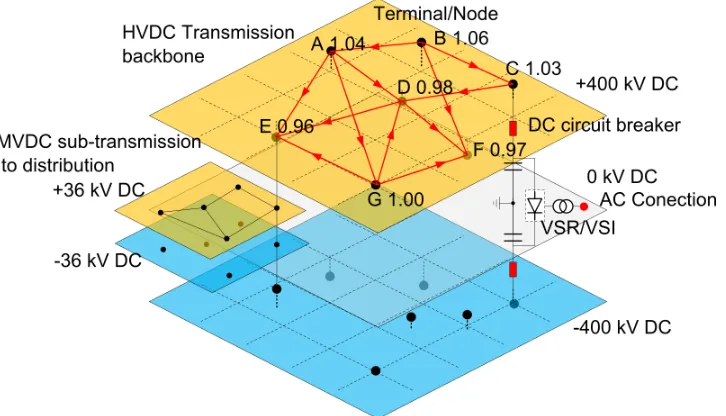
Figure 1.1 Connections of DC terminals into a DC grid. . . 2
Figure 1.2 Interconnected DC and AC system. . . 2
Figure 1.3 Conceptional diagram of a DC network and its power flow. . . 3
Figure 1.4 Voltage drops of solid state and hybrid circuit breakers. . . 7
Figure 1.5 Speeds of solid state and hybrid circuit breakers. . . 9
Figure 1.6 A passive oscillatory DC circuit breaker. . . 12
Figure 1.7 Interruption of 5 kA DC current via a passive oscillatory DC circuit breaker, simulated results. . . 13
Figure 1.8 Interruption of 5 kA DC current via a passive oscillatory DC circuit breaker, tested results. . . 13
Figure 1.9 A active oscillatory DC circuit breaker. . . 15
Figure 1.10 Interruption of 5 kA DC current via a active oscillatory DC circuit breaker, simulated results. . . 16
Figure 1.11 Interruption of 5 kA DC current via a active resonant DC circuit breaker, tested results. . . 16
Figure 1.12 A solid state circuit breaker using asymmetric IGBTs. . . 18
Figure 1.13 A solid state circuit breaker using symmetric SiC ETOs. . . 19
Figure 1.14 Hybrid circuit breaker using IGBTs. . . 20
Figure 1.15 A vacuum circuit breaker with PMA (in the open position). . . 23
Figure 1.16 Distribution of the magnetic field lines (in the open position). . . 24
Figure 1.17 Distribution of the magnetic field lines (shortly before the start of the motion). 24 Figure 1.18 Distribution of the magnetic field lines (after the end of the motion and before switching off the coil-current). . . 24
Figure 1.19 A fast mechanical switch based on TCA. . . 25
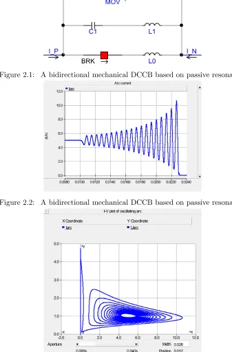
Figure 2.1 A bidirectional mechanical DCCB based on passive resonance. . . 36
Figure 2.2 A bidirectional mechanical DCCB based on passive resonance. . . 36
Figure 2.3 I-V characteristic of a passive oscillatory DC circuit breaker during current interruption. . . 36
Figure 2.4 A bidirectional mechanical DCCB based on active oscillation. . . 38
Figure 2.5 A unidirectional mechanical DCCB based on active oscillation (can be ex-tended to bidirectional). . . 38
Figure 2.6 A bidirectional mechanical DCCB based on active oscillation. . . 38
Figure 2.7 A mechanical DCCB using transverse magnetic field for commutation. . . 39
Figure 2.8 A thyristor based bidirectional DCCB, the isolated charger for the capacitors are not shown. . . 41
Figure 2.9 A thyristor based bidirectional DCCB. . . 42
Figure 2.10 A thyristor based bidirectional DCCB. . . 42
Figure 2.11 A thyristor based unidirectional DCCB. . . 43
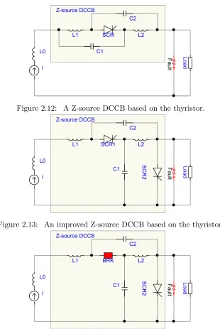
Figure 2.12 A Z-source DCCB based on the thyristor. . . 46
Figure 2.14 The proposed Z-source DCCB based on a fast mechanical switch. . . 46
Figure 2.15 A solid state DCCB based on fully controllable switches, such as IGBTs. . . 47
Figure 2.16 A general hybrid solid state DCCB. . . 48
Figure 2.17 A hybrid solid state DCCB based on thyristors. . . 50
Figure 2.18 A hybrid solid state DCCB based on thyristors and IGCTs. . . 50
Figure 2.19 Topology: A hybrid solid state DCCB based on thyristors. . . 50
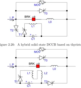
Figure 2.20 A hybrid solid state DCCB based on thyristors. . . 51
Figure 2.21 A hybrid DCCB based on thyristors, inspired by the topologies in Figs. 2.7 and 2.20. . . 51
Figure 2.22 A active oscillatory DCCB based on thyristors, inspired by the topologies in Figs. 2.7 and 2.20. . . 52
Figure 2.23 Areva TA topology: A hybrid solid state DCCB employing a solid state com-mutating switch. . . 52
Figure 2.24 ABB topology: A hybrid solid state DCCB employing a solid state commu-tating switch. . . 53
Figure 2.25 SGCC topology: A hybrid solid state DCCB employing a solid state commu-tating switch. . . 54
Figure 2.26 KIT Topology: A hybrid solid state DCCB employing a solid state commu-tating switch. . . 54
Figure 2.27 KIT - Topology: A hybrid solid state DCCB employing a solid state commu-tating switch. . . 55
Figure 2.28 Topology: A hybrid solid state DCCB employing a liquid metal fault current limiter as the commutating switch. . . 56
Figure 2.29 Topology: A hybrid solid state DCCB employing a arc generator as the com-mutating switch. . . 56
Figure 2.30 Topology: A hybrid solid state DCCB employing a transformer as the com-mutating switch. . . 56
Figure 2.31 Topology: A hybrid solid state DCCB employing a charge storage diode in the secondary path as the commutating switch. . . 57
Figure 2.32 Siemens Topology: A hybrid capacitor-aided DCCB employing a solid state commutating switch. . . 58
Figure 2.33 Alstom Topology: A hybrid capacitor-aided DCCB employing a solid state commutating switch. . . 58
Figure 2.34 Surge-less Topology: A hybrid capacitor-aided DCCB employing a solid state commutating switch. . . 58
Figure 3.1 2D view of a coil above a plate. . . 64
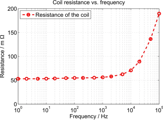
Figure 3.2 Coil resistance vs. excitation frequency. . . 65
Figure 3.3 Coil inductance vs. excitation frequency. . . 66
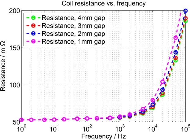
Figure 3.6 Coil resistance vs. excitation frequency with different gaps. . . 66
Figure 3.4 Coil current vs. excitation frequency. . . 67
Figure 3.7 Coil inductance vs. excitation frequency with different gaps. . . 67
Figure 3.5 Coil force vs. excitation frequency. . . 68
Figure 3.9 Coil current vs. excitation frequency with different gaps. . . 69
Figure 3.10 Coil force vs. excitation frequency with different gaps. . . 69
Figure 3.11 Interaction between multi-physics in the Thomson coil actuator mechanism. . 71
Figure 3.12 Current density in phi-axis. . . 75
Figure 3.13 Transients during opening operation. . . 76
Figure 3.14 Lorentz force in z-axis. . . 77
Figure 3.15 Lorentz force in r-axis. . . 77
Figure 3.16 Bidirectional circuit . . . 78
Figure 3.17 Unidirectional circuit . . . 78
Figure 3.18 Comparison of unidirectional and bidirectional circuit . . . 78
Figure 3.19 Actuator performance at different voltages. . . 80
Figure 3.20 Actuator performance at different capacitances and frequencies. . . 80
Figure 3.21 Actuator performance at different gaps. . . 81
Figure 3.22 Actuator performance at different disk thicknesses. . . 81
Figure 3.23 Actuator performance at different wire diameters. . . 82
Figure 3.24 Actuator performance at different disk outer diameters. . . 82
Figure 4.1 Structure of the FMS. . . 87
Figure 4.2 Circuit 1, first single pulse drive circuit. . . 88
Figure 4.3 Circuit 2, second single pulse drive circuit. . . 88
Figure 4.4 Circuit 3, bidirectional drive circuit. . . 88
Figure 4.5 Circuit 4, pulse forming network drive circuit. . . 89
Figure 4.6 Circuit 5, two-stage drive circuit. . . 89
Figure 4.7 FEA simulation model, 3-D view. . . 90
Figure 4.8 Von Mises stress distribution, 2-D view. . . 90
Figure 4.9 Currents and forces of Circuits 1, 2, 3. . . 92
Figure 4.10 Displacements and velocities of Circuits 1, 2, 3. . . 92
Figure 4.11 Currents when driven by PFN with different delays. . . 95
Figure 4.12 Forces when driven by PFN with different delays. . . 95
Figure 4.13 Displacements when driven by PFN with different delays. . . 96
Figure 4.14 Mechanical stresses when driven by PFN with different delays. . . 96
Figure 4.15 Currents of Circuit 5 with different C1 and U1. . . 98
Figure 4.16 Forces of Circuit 5 with different C1 and U1. . . 98
Figure 4.17 Displacements of Circuit 5 with different C1 and U1. . . 99
Figure 4.18 Zoomed-in displacements of Case 1 and Case 2. . . 99
Figure 4.19 FMS prototype assembly. . . 101
Figure 5.1 A typical vacuum interrupter. . . 104
Figure 5.2 Thyristor control switch. . . 107
Figure 5.3 A disc spring . . . 108
Figure 5.4 Load-deflection curves of a disc spring at different h/t ratios . . . 109
Figure 5.5 Load-deflection curve of a disc spring . . . 111
Figure 5.6 Photo of the disc spring used. . . 112
Figure 5.8 UFMS prototype assembly. . . 115
Figure 5.9 Opening operation (test data). . . 116
Figure 5.10 Closing operation (test data). . . 117
Figure 5.11 Repeatability of opening operations. . . 118
Figure 5.12 Repeatability of closing operations. . . 119
Figure 5.13 The model before modification. . . 119
Figure 5.14 The modified model. . . 119
Figure 5.15 Opening speeds at different driving voltages. . . 120
Figure 5.16 Modified simulation and measured results. . . 120
Figure 5.17 Modified simulation and measured results. . . 121
Figure 5.18 Modified simulation and measured results. . . 121
Figure 6.1 Successful opening driven by 400 V. . . 123
Figure 6.2 Opening driven by 420 V followed by a reclosing. . . 124
Figure 6.3 Multiphyics interaction in the actuator. . . 125
Figure 6.4 3D view of the FEM model. . . 125
Figure 6.5 Induced current in the plate, 60 us after energization of the opening coil, simulation result in axisymmetric 2D view. . . 126
Figure 6.6 Induced current in the plate, 440 us after energization of the damping coil, simulated result in axisymmetric 2D view. . . 127
Figure 6.7 Driving force (from 0 to 2 ms) and damping forces (from 2 to 4 ms), simula-tion results. . . 128
Figure 6.8 Speed and displacement curves corresponding to Fig. 6.7 forces, simulated results. . . 129
Figure 6.9 Test setup of the active damping for a Thomson coil actuated fast mechanical switch (safety enclosure removed for picture). . . 129
Figure 6.10 Test results performed with an active damping voltage of 322 V. . . 131
Figure 6.11 FMS motion for various opening voltages, with 2.0ms damping delay and 322 V damping voltage. . . 132
Figure 6.12 FMS motion for various opening voltages, with 2.0ms damping delay and 345 V damping voltage. . . 133
Figure 6.13 FMS motion for various opening voltages, with 3.0ms damping delay and 322 V damping voltage. . . 134
Figure 6.14 FMS motion for various opening voltages, with 3.0ms damping delay and 345 V damping voltage. . . 135
Figure 6.15 FMS motion for various opening and damping voltages, with 3.0 ms delay. . 135
Figure 6.16 FMS motion for various damping pulse timings with 430 V opening voltage and 322 V damping voltage. . . 136
Figure 6.17 FMS motion for various damping pulse timings with 430 V opening voltage and 345 V damping voltage. . . 136
Figure 6.18 FMS velocity pattern for various opening voltages, with 2.0 ms damping delay and 322V damping voltage. . . 137
Figure 7.1 Hybrid DCCB diagram. . . 139
Figure 7.2 Voltage and current profiles during circuit interruption. . . 140
Figure 7.3 Closing and opening operation sequences. . . 140
Figure 7.4 AB and FMS conduct current in normally operation. . . 142
Figure 7.5 To trip, AB and FMS open, current is commutated to MB. . . 142
Figure 7.6 MB turns off, MOV brings line current to zero. . . 142
Figure 7.7 Current commutation. . . 143
Figure 7.8 Equivalent circuit of current commutation. . . 144
Figure 7.9 IV curve of 15 kV SiC p-GTO. . . 145
Figure 7.10 SiC ETO turn off without snubber at 6 kV/ 120 A. Red:VKA. Blue:IK . . . 146
Figure 7.11 SiC ETO turn off with snubber at 7 kV/ 225 A. Red:VKA. Blue:IK . . . 146
Figure 7.12 Voltage divider for zero voltage turn on. . . 148
Figure 7.13 Inductive interruption test circuit of the hybrid DC circuit breaker. . . 149
Figure 7.14 Inductive interruption test circuit of the hybrid DC circuit breaker: operation sequence. . . 150
Figure 7.15 Inductive interruption test circuit of the hybrid DC circuit breaker: voltage clamping. . . 150
Figure 7.16 Inductive interruption test circuit of the hybrid DC circuit breaker: voltage clamping. . . 151
Figure 8.1 Current and voltage profiles of a hybrid DC circuit breaker with a commu-tating switch during interruption. . . 154
Figure 8.2 Diagram of the Thomson coil actuator based fast mechanical switch. . . 157
Figure 8.3 Total interruption time as a function oftFMS at different speeds. . . 157
Figure 8.4 Total interruption time as a function oftFMS at different system voltages. . . 158
Figure 8.5 Total interruption time as a function oftFMS with different currents. . . 159
Figure 8.6 A loglog plot of the breakdown voltage, UB, as a function of contact gap in vacuum [1]. . . 161
Figure 8.7 A linear plot of the breakdown voltage, UB, as a function of contact gap in vacuum [1]. . . 161
Figure 8.8 A design that meets 1300 g payload, 2 ms operation time target. . . 163
Figure 8.9 The 3D view of the design. . . 165
Figure 8.10 Operation transients of a design that meets 1300 g payload, 2 ms operation time target. . . 165
Figure 8.11 Displacement and velocity during operation. . . 166
Figure 8.12 Force and impulse transients during operation. . . 167
Figure 8.13 von Mises stress transients during operation. . . 167
Figure 8.14 Current transients and stress during operation. . . 168
Figure 8.15 The energy storage and control unit. . . 169
Figure 8.16 A thyristor module. . . 169
Figure 8.17 Current constriction at the actual point of contact, [2] (Page 206). . . 170
Figure 8.19 Popping force as a function of current. . . 173
Chapter 1
Introduction
As electric power transmission and distribution systems continue evolving, the structure and backbone of the system change, and the requirement of the performance and response of systems are more challenging. A few notable challenges include the endeavor to achieve higher energy efficiency, higher power quality and a more robust system. DC systems, no matter in low voltage micro-grid level, or medium voltage distribution level and high voltage transmission level, are considered the most promising to achieve these goals.
This thesis deals with the most challenging topic of DC systems: the DC circuit breakers. It investigates how various DC circuit breakers work; what is the requirement for such breakers; the design of the key component - the ultra-fast mechanical switch; the optimization and advanced control of the mechanical switch; and the optimization and control strategy of high voltage DC circuit breakers.
1.1
Benefits of DC grid systems
Figure 1.1: Connections of DC terminals into a DC grid.
Figure 1.2: Interconnected DC and AC system.
The benefits brought by DC grids rather than AC grids include:
1. Only active power is transmitted through the DC network; thus transmission as well as distribution systems could be rated only for the active power.
2. Conductors are more cost-effective, because they are designed for average and constant values rather than peak values of AC systems. Besides, there is neither skin effect nor proximity effect in DC.
3. Without charging current, DC cables make DC grids more feasible. For AC overhead lines, it is difficult to get the permission for new line corridors than ever because of environ-mental, ecological, political, and safety considerations. For AC cables, which dominate the investment largely in transmission schemes, inherent capacitance effect makes them much less cost-effective. But DC cable systems have no such problems.
Figure 1.3: Conceptional diagram of a DC network and its power flow.
such as the case of affected network by the Sandy storm in northeastern U.S., 2012.
5. DC grids can better integrate offshore energy parks through cable systems, such as wind park or wave energy park, and better in-feed cities through cable systems.
6. DC grids offer faster control response than AC grids. Since semiconductors can switch in microseconds and power electronics converters has less inertia, their controllability is better in both speed and preciseness.
7. AC/DC converters using self-commutated devices are able to control active and reactive power independently, so that a more flexible control over the connected AC systems can be achieved.
8. DC connections are the only way to connect AC systems operated at different frequencies or phase angles, which are often the cases when interconnections between regional grids or across the borders are needed.
dis-tance of more than 500 km, and capacity of several GW.
The benefits brought by DC grids rather than two-terminal HVDC connections include:
1. Multiple converter stations at one terminal are eliminated in DC grids, but multiple connections with other terminals to every DC node are still available. This greatly reduces the number and thus the cost of converters.
2. Frequency support requested by one or more interconnected AC systems could be handled by all the rest AC systems in a short time, and this burden is to be shared between them through the DC network.
3. When different regions are connected by a large DC grid, power support could also be distributed among each of nodes in the grid, and power deviation of the whole systems can be attenuated.
1.2
Challenges of Protections in DC Grid Systems
1.2.1 Interruption of DC circuits
1.2.2 Interruption Speed
For a voltage source converter based DC grid, once there is a short circuit, the DC bus voltage could drop very quickly and in the same time the short circuit current rises very fast if the faulted segment is not cleared and isolated quickly. If the DC voltage drops too low, all con-nected terminals may need to block out as preset by their own protection functions. The power transmission is interrupted for the whole DC grid which could consequentially cause instability in larger areas. If the short circuit current is too high, the value can go beyond the interruption capacity of installed DC circuit breaker and cause the equipment as well as the system to fail. Therefore, the operation speed is crucial for the protection of DC grids. Ideally, the time should be as short as possible. Generally, researchers and manufacturers are targeting a few milliseconds as the total interruption time.
The speed requirement can be less stringent if current limiting inductors are installed in the lines or cables. However, such inductors store magnetic energy during normal operation and short circuit conditions that puts additional duty on the energy absorbers of the DC circuit breakers. On the other hand, considerations regarding the transients and system control should be given if such inductors are installed.
1.2.3 Interruption Capacity
In conventional AC circuit breakers, the interruption capacity is expressed in MVA which is the product of the rated voltage and the maximum current that can be interrupted at this voltage. This definition applies to DC circuit breakers as well. However, it is suggested that in the calculation the system voltage is replaced by the MOV clamp voltage value, which is also called transient interruption voltage (TIV).
The required interruption capacity of a DC circuit breaker is related to its operation speed and the system parameters such as the impedance of the transmission conductors, the nominal voltage and current, and the capacitance of the DC capacitors.
to the fast rise rate of fault current. If the nominal voltage and current are high, the circuit breaker needs to withstand higher voltage during and after current interruption.
1.3
High Voltage DC Interruption Technologies
High voltage DC interruption technologies can be divided into two main groups: mechanical based solutions and solid state based solutions. This section first provides a comparison of general mechanical and solid state switches.
1.3.1 Comparison of mechanical and solid state switches
What distinguish a mechanical circuit breaker and a solid state breaker are mainly in the following three aspects:
1. The voltage drop
A mechanical switch’s voltage drop when conducting a current is dependent on its contact resistance. The contact resistance is a function of the area of the effective contact surface, the condition and material of the contact surface, and the force applied to the contacts. If additional holding force is applied to the mechanical contacts, which are essentially made of certain metal with special coatings, the contact resistance is in the range of tens of micro-Ohms. Therefore the voltage drop when conducting hundreds of amperes of current is only in the range of tens of milli-Volts, and the power loss is only about a few watts, which does not require additional cooling auxiliaries.
Figure 1.4: Voltage drops of solid state and hybrid circuit breakers.
both types of carriers are contributing to current transportation. Therefore the voltage drop is much lower at higher current. However, they still exhibit a few volts of voltage drop during conductions which means hundreds or even thousands Watts of power loss. Additional cooling is required for such devices, which adds not only extra cost but also complexity, power loss and footage to the overall design.
2. The current turn-off mechanism and capability
The current in mechanical circuit breaker is cut off by the extinction of an arc which serves as an conduction path after contacts are open. Once the arc is extinguished and the open gap between contacts are sufficiently wide to withstand the forthcoming transient over voltage (TRV), the circuit is interrupted and the networks on both sides of the circuit breaker are isolated from each other.
designed TRV level after arc extinction. Otherwise, a restrike happens between the gap because of high TRV or high rate of rise of recovery voltage (RRRV).
The turn off mechanism for solid state switches differ from one device to another. Take IGBTs for an example. Once the positive gate voltage is put on zero or a negative value, the gate voltage reduces linearly for a short period to Miller Plateau. Negative gate current draws current from the nonlinear capacitance CGC and increases VCE. As VCE reaches
source voltage, VGE continues decreasing and IC starts to drop. Due to the minority
carriers stored in the n-base region, a current tail is observed. In the meanwhile the space charge is built-up to withstand the voltage. The turn-off capability of a semiconductor device is defined by its reverse blocking safe operation area (RBSOA). With snubber circuits, the dv/dt is reduced and the device can potentially turn off much more current. In circuit breaker applications, the snubber circuits may take a few us to charge to the clamped voltage level, but this period is still very short compared to mechanical circuit breakers and therefore would be in favor for the circuit breaker to turn off a large current.
3. The operation speed
The time for a conventional mechanical circuit breaker to interrupt a current is in the range of tens of milliseconds, while for semiconductors it is in the order of microseconds, or even faster.
Figure 1.5: Speeds of solid state and hybrid circuit breakers.
the actual payload which is the movable contact. The additional moving mass takes some time to overcome the inertial and gain sufficient momentum, which adds to the total interruption time. If SF6 is used as the dielectric, a single pressure or double pressure structure is usually used. In such structures, pressurized SF6 gas is released when the nozzle is opened and helps cool down the burning arc. Additional time is needed for this pressurization period which also makes the total operation time longer.
1.3.2 DC interruption method classification
In this thesis, the high power dc interruption methods are grouped into two categories mainly based on how the DC current is interrupted: mechanical technologies and solid state technolo-gies. It’s often easy to tell one from another, but for some hybrid techniques or techniques that include both high voltage semiconductors and high voltage mechanical switches, it can be a little confusing. Therefore the following definitions are used to classify DC interruption methods. If a mechanical breaker is used and arcing and arc extinguishing are evolved, it is classified as a mechanical interruption method; if the current is interrupted by turning off a semiconductor device without arcing, then it is called a solid state method. Mechanical DCCB includes passive and active oscillatory DCCBs, and solid state DCCB includes pure solid state and hybrid DCCBs.
1.3.3 Mechanical Technologies
There are a few typical mechanical DC interruption methods, in which the arc current is su-perimposed with an artificially created reverse current so the total arc current can be brought to zero at a certain instant.
One way to create a current zero in an arc is to form an oscillating circuit of which the oscillation magnitude increases with time. This method takes the advantage of the negative resistance characteristic of gaseous arcs. The parallel circuit is capacitive and under-damped. A high arc voltage is desired so that the oscillating current could be as high as to cancel out the line current in the arcing path. Oscillation frequency and the instability of the circuit also affects the time for the arc to be extinguished. The design of the circuit is very much dependent on the arc characteristics of the mechanical circuit breaker that is used. The time of circuit interruption is in the range of tens of milliseconds. If gaseous circuit breakers are used and higher arc voltage is preferred, pressurization is needed before arc is formed, and this potentially increases the total interruption time.
into the mechanical circuit breaker during the arcing period. The injected reverse current is mostly determined by the capacitance, the pre-charged voltage and the loop parameters. This current is of high frequency and high magnitude. Once discharging is initiated, a current zero can be formed very quickly. As a high arc voltage is not necessary for this scheme, vacuum interrupters and simplified operating mechanisms could be used. Therefore these DCCBs can be potentially faster than those gaseous interrupters.
1.3.4 Solid State Technologies
There are different power devices that can interrupt a DC current, and the device selection could differ from one application to another. Modern power devices that are suitable for circuit interruption purposes and most seen in publications include power MOSFET, IGBT, Thyristor, GTO, IGCT and ETO, etc.
From gate control point of view, MOSFET and IGBT are voltage controlled devices whose drive circuits could be much simpler than current controlled devices such as Thyristor type devices (Thyristor, GTO, IGCT, ETO). From current conduction and switching capability point of view, only MOSFET is of unipolar type among the listed devices and therefore it switches very fast but has less current capability. Different from all other devices, thyristors rely on external commutation mechanisms to turn off current rather than via its gate.
This section aims to identify different interruption schemes rather than various device op-eration physics, so a DC interruption that employs IGBTs are considered same as another one that uses MOSFETs or IGCTs or ETOs, even though these power devices can be fundamentally different from each other in terms of their conduction, blocking and turn-off capabilities.
1.4
Passive Oscillatory DC Circuit Breakers
Passive oscillatory DC circuit breakers are already used in conventional HVDC and UHVDC transmission systems but they are actually called DC transfer switches considering that their main function is to transfer DC current from one circuit to another. They are the earliest solutions for high voltage high power applications in the 1970s to 1990s motivated by the wide adoption of thyristor based HVDC transmission schemes worldwide. Researchers from industries as well as universities from Europe, Japan, United States and China have investigated this scheme both fundamentally and experimentally.
1.4.1 Operation Principle
The diagram of a passive oscillatory DCCB is shown in Fig. 1.6. The circuit is composed by a SF6 circuit breaker, a high voltage capacitor bank, an inductor (sometimes omitted), and metal-oxide varistors (MOVs).
Figure 1.6: A passive oscillatory DC circuit breaker.
Figure 1.7: Interruption of 5 kA DC current via a passive oscillatory DC circuit breaker, simulated results.
Figure 1.8: Interruption of 5 kA DC current via a passive oscillatory DC circuit breaker, tested results.
The magnitude of the oscillation increases over time when the LC circuit has proper parameters. It is desired that loop resistance is minimized so that the oscillation is not damped quickly. Both the arc characteristics and RLC circuit parameters play important roles in the process of DC current interruption.
PSCAD and test results from a prototype built for UHVDC transmission systems.
Using computational fluid dynamics (CFD) and finite element analysis (FEA) methods, the arc itself can also be modeled with physics rather than circuits. Such modeling work could take a lot of modeling and computation efforts.
1.4.2 Advantages and Limitations
Thanks to the simple circuit, only passive components are added to a conventional AC circuit breaker. No auxiliary power or control logic is needed. The trip or close signals sent to the ACCB can be considered the same to the whole DCCB. During normal operation, the conventional ACCB conducts current with minimum losses.
The limitation lies in the operation speed or the interruption time. The total interruption time is defined as the instance from the trip signal to the moment the current of the circuit is brought to zero. For a passive oscillatory DCCB based on conventional SF6 circuit breakers, the interruption time can be roughly divided into three periods: the opening time, the arcing time, and the demagnetization time.
Due to the arc chamber structure and the necessity of compressing and releasing SF6 gas for arc extinguishing, more opening time is required for such circuit breakers, typically around 20 ms or longer. The need for higher arc voltage also justifies the puffer or self blast structure. The arcing time is the time from the start of arcing to the moment the oscillation reaches a zero current. As mentioned before, this time depends on the arc characteristics (arc voltage and negative resistance), the RLC circuit parameters and the magnitude of the current to be interrupted. This time is around 20 ms, which is sufficient for the DCCB to gain dielectric strength to withstand the TIV. For the DC system protection point of view, this response is too slow.
1.5
Active Oscillatory DC Circuit Breakers
The active oscillatory DCCBs has a pre-charged capacitor bank instead of a passive and un-charged one. Therefore, a charging circuit with high voltage isolation is often required, which added to the complexity of the whole unit. They may or may not consists an inductor, but must have MOVs.
1.5.1 Operation Principle
Though active resonant DCCBs seems very similar to passive resonant DCCBs from circuit diagram point of view, they vary from each other fundamentally and can be very different in terms of performance. The most significant difference is that the operation speed of the active resonant DCCB can be really quick because of two reasons. First, simple and light-weighted vacuum circuit breaker rather than a SF6 circuit breaker can be used, and therefore its opening time can be minimized using an ultra-fast operating mechanism. Most vacuum circuit breakers have butt type contacts and requires no over-travel or pressurized gas flow. Furthermore, because the active resonant cause by current injection from a pre-charged capacitor bank, this current injection could be very fast and of high magnitude which easily creates an artificial current zero in sub-milliseconds. Figs. 1.9 to 1.11 shows the circuit diagram and operation transients [4].
Figure 1.10: Interruption of 5 kA DC current via a active oscillatory DC circuit breaker, simulated results.
Figure 1.11: Interruption of 5 kA DC current via a active resonant DC circuit breaker, tested results.
1.5.2 Advantages and Limitations
Active oscillatory DCCBs can interrupt a lot of kA DC current as long as the reverse current can be injected.
charging and current injection circuit.
On the other hand, since the injection is of high frequency, it poses challenges to the mechan-ical circuit breaker to withstand fast rising TRVs after the arc extinction. Also, the moment to initiate the injection needs to be optimally predefined and precisely controlled. Otherwise, the open gap may be too small to withstand forthcoming TRV after arc extinction. If the capacitor bank is pre-charged to a fixed voltage level, a current zero could be reached at different times if the fault current is at different levels.
1.6
Solid State DC Circuit Breakers
Solid state devices are able to turn off a current running through the device by changing their carrier flow conditions and behaviors in a few microseconds or even less. Besides their fast re-sponse, the other advantage of solid state devices is that they can repeatedly operation with vir-tually no wearing or erosion in contrast to mechanical circuit breakers. Depending on the devices that are used, there are a lot of variations of this technology. Commonly used power devices for power switching in circuit breakers are Insulated Gate Bipolar Transistors (IGBT), Metal-Oxide Semiconductor Field Effect Transistors (MOSFET), thyristors, gate turn-off (GTO) thyristors, emitter turn-off thyristors (ETO), and Integrated Gate Controlled thyristors (IGCT). Among them, IGBT and MOSFET are transistor type devices, while others are thyristor type. All listed devices except the thyristor can be turned off though gates. Therefore, to use thyristors in DC circuit breaker, one has to create a current zero similar to the case of mechanical circuit breakers.
Figure 1.12: A solid state circuit breaker using asymmetric IGBTs.
1.6.1 Solid State Device Characteristics
The topology and the number of devices needed differ according to the device characteristics. Generally speaking, a circuit breaker should be able to block the voltages across it irrespective of the polarities and to conduct and interrupt current from both directions.
A device that can blocking both forward and reverse bias voltages are called a symmetric device. In power electronics applications, they are usually used in current source converters. Therefore, thyristors and GTOs are available with reverse blocking capabilities the same as the forward blocking ratings. However, this adds to the forward voltage drop because of a thick or long low doped region for the reverse blocking junction. IGBTs can be monolithically modified into symmetric versions as well [6]; or they can be packaged with discrete diodes into modules. Devices such as MOSFETs can conduct bidirectional current themselves because of their parasitic diode. Other devices, such as IGBTs, thyristors would need a second device (swich or diode) in parallel or a monolithic integrated diode to conduct the reverse current [7, 8, 9].
Though both bidirectional voltage blocking and current conduction can be achieved mono-lithically, no single commercially available device can turn off current in both directions.
Figure 1.13: A solid state circuit breaker using symmetric SiC ETOs.
1.6.2 Operation Principle
The turn on and turn off processes in different types of devices are different. Take the n-type ETO device for example, there are two stages in a current turn-off process. The first step is to commutate current from cathode to the gate so that the line current flow through the device’s p-n-p layers. Then the ETO acts like an open base p-n-p transistor so that the current is turned off.
If there is no capacitor across the semiconductor device, the voltage across it would surge to a high magnitude very quickly. This is especially the case if the line inductance is significant. MOVs are needed to prevent such overvoltages, protect the semiconductor devices, and bring the line current to zero.
1.6.3 Advantages and Limitations
Most power semiconductors have limited voltage and current ratings for direct use in power systems, and causes excessive power losses at operation. By series and parallel connection, their ratings can be scaled up. However, considerations in voltage balance and current sharing usually result in more complexity in the circuit and structure. Even if these issues can be addressed, the undesirable conduction losses make it a less viable option.
and reliability.
1.7
Hybrid DC Circuit Breakers
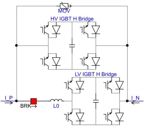
Hybrid solutions have been proposed to combine the merits of both mechanical and solid state switching devices. A most intuitive scheme is the one shown in Fig. 1.14, composed by three parallel branches: the mechanical switch, the solid state switch, and the MOV circuit. The mechanical switch is the primary conducting path during normal operation; the solid state switch takes over the current after the mechanical switch opens and turns off the DC current without arcing in microseconds; the MOVs clamp the voltage, absorb the magnetic energy and bring down the current in the line.
Figure 1.14: Hybrid circuit breaker using IGBTs.
1.7.1 Operation Principle
Compare the mechanical switch in this hybrid scheme with conventional AC circuit breakers, this mechanical switch still has to draw an arc during operation, and to withstand the arc burning. Therefore the contacts still needs to be treated specially, coated with special alloys. However, in the case of the hybrid DCCB, the arcing time and arc energy depend on the commutation process rather than the line currents: for a given loop inductance and current, the higher arc voltage, the shorter commutation time, and the less arc energy to be absorbed. In this sense, the low arc voltage of vacuum circuit breakers is not desirable as they are typically 20 to 30 Volts. For a 10 uH loop, 1000 A takes 300 to 500 us to commutate. Then a dielectric recovery period is required before the turn off of solid state switches so that the transient recovery voltage (TRV) does not cause a restrike across the mechanical switch.
An improved hybrid solution uses a low voltage solid state commutating switch [10, 11, 12] so that the current can be commutated in far less time, and the mechanical switch operation under zero voltage zero current conditions. Therefore the mechanical switches are free of arcing during operations, and could be easily manufactured.
1.7.2 Advantages and Limitations
The improved hybrid solution with a low voltage solid state commutating switch has been considered one of the most promising technologies so far. A 80 kV module for a 320 kV 9 kA DCCB has been developed and tested by ABB using IGBTs and fast mechanical switches. The total interruption is reported as approximately 5 ms.
As the solid state switch can withstand overvoltage in a few us, it is not to turn off until the moment that the opening gap of the mechanical switch can withstand designed voltage level. Such ultra-fast mechanical switches are far from available. ABB’s fast disconnect switch has a reported open operation time of 2 ms for the 80 kV module. Though acceptable, faster operation is always desirable and beneficial.
pose challenges to the reliability and the foot print tends to be large.
1.8
Ultra-fast Mechanical Switches
Ultra-fast mechanical switches are the mechanical switches designed for active oscillatory DCCB or hybrid DC circuit breakers that can open to a certain gap in a few milliseconds or sub-milliseconds. It is the key component for low loss conduction and fast interruption in such DC circuit breakers. This mechanical operation speed has twofold meaning for the total interruption time. First, the opening time takes almost half of the total time. Second, if the speed is faster and therefore within the same time a larger separation is achieved so that higher TRV is allowed, the time to bring down line current is reduced. Therefore, this section gives an overview of possible fast actuation method that can be used in such mechanical switches. To summarize, the UFMS needs to meet the following requirements: 1) Low conduction losses. 2) Fast operation speed, especially the opening speed. 3) Reliably remained in open and closed positions during steady state.
1.8.1 Solenoid and permanent magnet actuator
Figure 1.15: A vacuum circuit breaker with PMA (in the open position).
directly onto the contacts of the vacuum interrupter.
Figure 1.16: Distribution of the magnetic field lines (in the open position).
Figure 1.17: Distribution of the magnetic field lines (shortly before the start of the motion).
Figure 1.18: Distribution of the magnetic field lines (after the end of the motion and before switching off the coil-current).
1.8.2 Repulsion coil actuator (Thomson coil actuator)
A typical repulsion coil actuator (TCA) based mechanical switch is shown in Fig 1.19. It is considered as a very fast actuator, and is preferred choice when fast acting of circuit breakers are required. Even though there are quite a few different factors that may affect the actuation of a moving object, such as the mass and the driving force, TCA generally can have a very short delay of force delivery, typically less than a few hundreds of microseconds. Compared to the solenoid type actuator, TCA respond much faster, thanks to its inherently less turns of windings. On the other hand, however, the efficiency of the TCA could be less.
Chapter 2
Review of DC Circuit Breaker
Technologies
This chapter mainly focuses on medium to high voltage high power DC circuit breakers because they are more challenging than low voltage DCCBs.
2.1
Introduction
2.1.1 Challenges of a high power high voltage DCCB Interruption of high power DC circuits
to the large amount of magnetic energy stored in the circuit, which increases as fault current rises up, varistors are always needed to absorb the energy.
Interruption Speed
For a voltage source converter based DC grid, once there is a short circuit, the DC bus voltage could drop very quickly and in the same time the short circuit current rises very fast if the faulted segment is not cleared and isolated. If the DC voltage drops to a value that is too low, all connected terminal may need to block out, and the power transmission is interrupted for the whole grid which could consequentially cause instability in larger areas. If the short circuit current is too high, the value can go beyond the interruption capacity of installed DC circuit breaker and cause the equipment as well as the system to fail.
Therefore, the operation speed is crucial for the protection of DC grids. Ideally, the time should be as short as possible. Generally, researchers and manufacturers are targeting a few milliseconds as the total interruption time.
The speed requirement can be less stringent if current limiting inductors are installed in the lines or cables. However, such inductors store magnetic energy during normal operation and short circuit conditions that they put additional duty on the energy absorbers of the DC circuit breakers. On the other hand, considerations regarding the transients and system control should be given if such inductors are to be installed.
Interruption Capacity
In conventional AC circuit breakers, the interruption capacity is expressed in MVA which is the product of maximum current that can be interrupted and the system voltage. This definition applies to DC circuit breakers as well with the system voltage is replaced by the MOV clamp voltage value.
the capacitance of the DC capacitors and its operation speed.
If the operation speed is slow, the circuit breaker will needs to interrupt a high current due to the fast rise rate of fault current. If the nominal voltage and current are high, the circuit breaker needs to withstand higher voltage during and after current interruption.
2.1.2 DCCBs and other switchgear DCCBs and ACCBs
The absence of current zero in a DC circuit cause more profound differences in DCCBs from ACCBs.
First some external mechanism is required to bring the current to zero rather than waiting for a current zero. The various mechanisms vary and will be discussed in details in the following sections.
What is noteworthy in AC circuit interruptions is that the actual current at the moment the arc is extinguished is not ideally zero. This phenomenon is called current chopping which can cause very high TRV and RRRV across the gap of the ACCB because of the residual magnetic energy stored in the system inductance. To deal with this problem, the interrupters are optimized to reduce current chopping level, or capacitors and MOV are used to absorb the energy and lower the TRV.
For a DCCB, the magnetic energy is even more problematic because the rising fault current is injecting more energy into the inductance which eventually needs to be absorb. Therefore, MOVs are always required for DCCBs.
DCCBs and FCLs
circuit breaker due to the expansion of existing transmission and distribution networks. So the main strategy of a FCL is to insert a high impedance to the circuit that reduced the fault current level.
On the other hand, circuit breakers are defined to interrupt a current and therefore the circuit. But sometimes a FCL is also able to interrupt a circuit, for example a pure solid state FCL that does not even include any high voltage inductors or capacitors.
DCCBs and current limiting ACCBs
DCCBs for the protections in VSC based DC systems needs to operate ultra fast compared to conventional ACCBs. The time scale for a DCCB is a few milliseconds or even less, which is about or preferably less than a quarter cycle in a 50 Hz or 60 Hz circuit. Therefore, if the DCCB is to interrupt an AC circuit, the ultra-fast interruption speed naturally limits the fault current level because typically it takes one to a few cycles to reach prospective fault current level in AC systems. However, due to the special circuits that are needed for some of the DCCBs, they are not guaranteed to function in AC circuits as well as in DC.
2.1.3 Key parameters of a DCCB Nominal voltage and maximum TIV level
The nominal voltage is the DC voltage of the system during normal operations and sets the insulation requirement for the design and operation of the DC circuit breakers.
The maximum TIV level is dependent on the voltage withstand capabilities of the DC circuit breaker components. In a hybrid DC circuit breaker topology that consists of a mechanical switch and a high voltage semiconductor switch in parallel, both two switches needs to withstand the TIV. Therefore, with a higher TIV level, more semiconductor devices are needed in series for the DCCBs, and a larger gap in the mechanical switch is needed as well. What is more important is that, the whole system needs to accommodate this relatively higher voltage for insulation purpose, which can cause a substantial increase in cost.
So the trade-off between the cost of the high voltage systems and the time to clear the fault is to be made when designing the hybrid DC circuit breakers. As reported in several recent prototypes from major manufacturers in high voltage DC equipment, the TIV is typically selected as 1.5 p.u. of the nominal system voltage, see Table. 2.1.
Nominal current and maximum interruption current
Nominal current sets the work condition for the primary current conducting path in the DC circuit breaker. A large current would require that the equivalent series resistance or voltage drop of the DC circuit breaker is sufficiently low.
For those having the mechanical switch as the primary conduction path, the contact resis-tance is a function of the contact area and material, the pressure applied to the contacts, and the surface condition of the contacts. Since fast opening is necessary for protection in HVDC grids, large contacts delay the acceleration for opening operation. Further more, the externally applied holding force for the sake of low contact resistance is another obstacle to overcome for the operation mechanism to open the contacts rapidly.
Break time
The break time is defined by the Cigre Joint Working Group A3.B4.34 as the time interval from the instant the breaker receives the trip order and the instant when the current has been lowered to leakage current level (or below) [15], which is analogous to the AC breaker standard (IEC 62271-100, 3.7.135) [16].
For DC circuit breakers of different principles and topologies, the components of the total break time differ. For a comprehensive treatment of the break time analysis, please refer to Chapter 8.
MOV energy capacity
Similar to the time for the MOV to bring down the line current to zero, the energy it needs to absorb is also a function of the line current, line inductance, the residual voltage level and the system voltage. To obtain more accurate results, it is suggested that the system under study is modeled and simulated using electromagnetic transient programs. However, generally speaking, larger line current, larger line inductance and higher system voltage result in more energy required to be absorbed; higher residual voltage level reduces this amount of energy.
2.1.4 Prior work
There has been very few publications reviewing DCCB or related technologies that have emerged in the past decade. In [17], C. M. Franck has reviewed the DCCB technologies from system requirement by HVDC network systems, to general DCCB technologies and has identified that a lot of work can be done to optimize current technologies and emerging devices to meet the requirement set by HVDC network systems based on voltage source converter. However, the review covers a lot of relevant topics of DCCBs, such as the description of HVDC networks, fault current limiters and testing methods, rather than focusing on the technological details of various DCCBs. In stead, only general principles of most typical DCCBs are introduced.
electronics for power switchings. Though the paper has been striving to give as much information about each topology as possible, it does not provide sufficient insights into the differences between the abundant but similar topologies. For example, this paper has failed to point out that once power semiconductor devices are used to switch off current, there is insignificant difference between AC and DC switching because the fast turn-off speed of semiconductors, which is in the range of microseconds, together with the arcless interruption capability eliminate the necessity of current zero crossings. Therefore, there is no need to differentiate AC and DC hybrid circuit breaker, especially if the DC circuit breaker is functional bidirectionally.
An interesting review paper [19] has published on fault current limiters by Alexander and Smedley in 2013. Though the paper focuses only on solid state type FCLs rather than DCCBs, it gives a good example of classification and comparison of a lot of similar yet different topologies, and can be very beneficial for the study of DCCBs.
[20] has provided a good introduction of available mechanical, solid state and hybrid DC circuit breakers from various aspects, and good lists of references and the state-of-the-art prod-ucts from industries. However, the report has missed out some important DCCB technologies, and is limited to DCCBs in the range of hundreds of Volts to a few kilovolts.
2.1.5 Necessity of the presented work
A classification method is crucial for the understanding of different DCCB topologies. Even though researchers have identified the most common DCCB types, various new topologies have been proposed in recent years, some of which might look similar to those common types but are essentially different in principle. A typical example is the so called hybrid circuit breakers, which are generally and intuitively understood as a circuit breaker including both a mechanical and a solid state elements. Without explicit classification criteria, inappropriately categorizing topologies as a hybrid DCCB can cause misleadingness.
in the past decades has motivated the research of DCCBs in both industry and academia. In the last five years, more than twenty patents and publications have arised which are only included or discussed by very few papers. For example, at the same publication time of Franck’s review, ABB has announced their proactive HVDC circuit breaker on Cigre in 2011, which is not covered by [18].
On the other hand, it is always advisable to look back to what have been done a few decades ago. Back in 1970s and 1980s, the work was also motivated by the vision of an interconnected DC network, though in a different way that converters are of current source nature. Quite a few full scale prototypes have been developed and tested by major power apparatus manufac-turers around the world. Their achievements are significant yet neglected in most of today’s publications.
Some work done on FCLs has been overlooked by researchers who are focusing on DCCBs, especially those proposed in the applied superconductivities community. Because of the am-biguity of the terminology of FCL, some of the FCLs can be used as DCCBs as well. This review will include such work so as to provide the readers a broader view and hopefully more inspirations.
2.2
Classification
A classification method is proposed to distinguish various different yet similar DCCB topologies and schemes, which will help researchers to better understand and identify the benefits, limits or bottlenecks for each type of DCCBs.
2.2.1 Classification criteria
A circuit breaker performs two basic functions: conducting a current, and interruption a current. So the criteria used to distinguish one DCCB from another is:
2. The actual current interruption mechanism.
2.2.2 Mechanical DC circuit breakers
In mechanical DCCBs, the mechanical part conducts the current in normal operation, and extinguishes arc when switching DC current.
Low voltage mechanical circuit breakers can interrupt a circuit by forming an arc voltage higher than the source voltage. This technique finds its application in DC circuit breakers up to 3 kV [21]. However, this method is not practical for system voltages above a few kilovolts. In stead, additional passive components or active components are added to aid the direct current interruption, usually by superimposed current resonance, at higher voltage levels. Therefore, mechanical DCCBs can be further grouped into two sub-categories: passive oscillatory DCCBs, and active oscillatory DCCBs.
2.2.3 Solid-state DC circuit breakers
In contrary to mechanical DCCBs, the solid state DCCBs conducts nominal current and inter-rupt the current both via solid state switches.
As discussed in Section 2.5, based on the characteristics of the devices used, solid state DCCBs can be classified into Thyristor based DCCBs and active switch based DCCBs.
2.2.4 Hybrid DC circuit breakers
Hybrid DCCBs usually conduct current mainly by the mechanical parts, but the DC current interruption is achieved by solid state switches.