Design of a Miniature Folded Patch Antenna
for Multiband Application
Chithra B Das
M.Tech Scholar, Department of ECE, MZCE, Kadammanitta, Pathanamthitta, Kerala, India
ABSTRACT: Wireless communications have developed greatly and demand for designing low profile antennas has grown. A miniature folded square patch antenna forGlobal Positioning System(GPS) application is considered. In this four different lengths of meander strips connected to the four edges of the square patch of a single coaxial-feed square patch antenna are folded to obtain a circularly polarized antenna. It is proposed to design a miniature folded antenna for Multi Band system in a single structure with bandwidth enhancement.PIFA (Planar Inverted-F Antenna) have the attractive features of low profile, small size, low cost, and conformability to mounting hosts. The proposed antenna has small in size and operates at 1.57GHz, 2.26GHz, 3.8GHz and 1.3 GHz suitable for GPS, Mobile Satellite Service (MSS) network, Wi-Max, Radar applications.
KEYWORDS: Global Positioning System,Mobile Satellite Service,Wi-Max, Planar Inverted-F Antenna.
I. INTRODUCTION
The Global Positioning System (GPS) is a space-based navigation system that provides location and time information in all weather conditions, anywhere on or near the Earth where there is an unobstructed line of sight to four or more GPS satellites. A GPS receiver monitors multiple satellites and solves equations to determine the exact position of the receiver and its deviation from true time. Circularly polarized patch antennas are widely used in mobile satellite communication systems, radio-frequency identification systems, global positioning systems (GPS) and most vehicle communication devices. In order to obtain the right-handed circular polarization four different lengths of meander strips connected to the four edges of the square patch of a single coaxial-feed square patch antenna are folded to obtain a circularly polarized antenna.Properly positioning the coaxial feed on the square patch excites two orthogonal resonant modes with a 90 phase difference and achieves a pure circular polarization at a GPS frequency of 1.575 GHz. It is proposed to design Multi Band system in a single folded PIFA structure with bandwidth enhancement on a FR4 substrate.The proposed antenna has small in size and operates at 1.57GHz, 2.26GHz, 3.8GHz and 4.3 GHz suitable for GPS, Mobile Satellite Service (MSS) network, Wi-Max, Radar applications.
II. RELATED WORKS
III.EXISTINGSYSTEM
In [1], the GPS antenna is printed on two layers of the first FR4 substrate (thickness, 1.6 mm); relative permittivity, 4.4).
Fig.1. Geometry of the circularly polarized folded patch antenna: top view
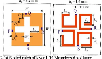
Fig. 2 (a) shows a cross slotted square patch with dimension etched on layer 1 and connected to layer 2 by four via holes (points P, Q, R and S) at the four edges of the square patch. Each arm of the cross-slot etched on the square patch is of length and width and can be tuned for impedance matching. Fig. 2 (b) shows that layer 2 of the first substrate is printed on four types of meander strip to extend the effective resonant length.
Fig.2 (a).Slotted patch of layer 1 (b) Meander strip of layer
A cross slotted square patch with dimension etched on layer 1 and connected to layer 2 by four via holes at the four edges of the square patch Layer 2 of the first substrate is printed on four types of meander strip to extend the effective resonant length. The front-ends of the strips are individually connectedto the four via holes with short wires. The same FR4 substrate (thickness, 1.6 mm) but without copper layers is attached to the bottom of the first FR4 substrate. The bottom substrate, which acts as a ground plane, is circular (radius 50mm; thickness1.6 mm) and only has a copper layer. Excitation of the antenna is provided by a single coaxial probe located at and on the orthogonal sides of the square patch.TABLE I shows the optimal parameter value of the GPS antenna
TABLE I
OPTIMAL PARAMETER VALUE OF THE GPS ANTENNA
parameters Value(mm) parameters Value(mm)
w 15 4.5
3 5.2
1 4
2 5.5
3.2 5.5
1.5 3
IV.PROPOSEDSYSTEM
It is proposed to design a single structure miniature multi band folded patch antenna for various frequencies. Fig.3. shows the Proposed Folded Multi Band PIFA Antenna.Planar inverted-F antenna (PIFA) is a type of patch antenna. Multiband PIFAs can be used to combine the antennae feeds for mobile phone, satellite navigation.Mobile satellite services (MSS) refers to networks of communications satellites intended for use with mobile and portable wireless telephones. MSS repeaters can be placed on geostationary, medium earth orbit (MEO), or low earth orbit (LEO) satellites.Provided there are enough satellites in the system, and provided they are properly spaced around the globe, an MSS can link any two wireless telephone sets at any time, no matter where in the world they are located.
Wi-MAX is a family of wirelesscommunications standards initially designed to provide 30 to 40 mbps data rates.International Telecommunication Union´s (ITU) defines radio altimeter is a navigation equipment, on board an aircraft or spacecraft, used to determine the height of the aircraft or the spacecraft above the Earth's surface or another surface Radionavigation equipment shall be classified by theradiocommunication service in which it operates permanently or temporarily. For the proposed structureFR4 substrate (thickness, 1.6 mm) of relative permittivity, 4.4) is chosen.TABLE II shows the optimal parameter value of the proposed antenna.
Fig.3. Proposed Folded Multi Band PIFA Antenna
l
b
a
f
e
c
d
h
TABLE II
OPTIMAL PARAMETER VALUE OF THE PROPOSED ANTENNA
Antenna Parameters value
a 1mm
b 9.46mm
c 17.33mm
d 9mm
e 1.38mm
f 4.1mm
g 3.96mm
h 5.28mm
l 25mm
V. SIMULATION RESULTS
A. Existing System
This section describes the simulated results of existing system. The simulated result is carried out by the help of HFSS.The simulated S-parameters of the folded square patch antenna for GPS application are shown in Fig. 4.
Fig.4. Simulated return loss for GPS application
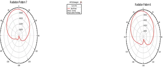
For this resonant frequencies are 1.455 GHz , 1.575GHz and 1.66GHz with return losses are -47dB,-22dB and -16.5dB respectively.Fig.5shows thesimulated radiation pattern (for = 0 90°).
Fig.5. Simulated radiation pattern for radiation pattern
1.40 1.45 1.50 1.55 1.60 1.65 1.70
Freq [GHz] -50.00 -40.00 -30.00 -20.00 -10.00 0.00 d B (S t( C y li n d e r4 _ T 1 ,C y li n d e r4 _ T 1 )) HFSSDesign1
XY Plot 3 ANSOFT
Curve Info
dB(St(Cylinder4_T1,Cylinder4_T1)) Setup1 : Sw eep
-26.50 -23.00 -19.50 -16.00 90 60 30 0 -30 -60 -90 -120 -150 -180 150 120 HFSSDesign1
Radiation Pattern 7 ANSOFT
Curve Info dB(rETotal) Setup1 : Sw eep Freq='1.4GHz' Phi='0deg' -28.50 -24.50 -20.50 -16.50 90 60 30 0 -30 -60 -90 -120 -150 -180 150 120 HFSSDesign1
Radiation Pattern 6 ANSOFT
B. Proposed System
This section describes the simulated results of Proposed Multi Band (MB) Antenna Structure. The simulated result is carried out by the help of HFSS.The simulated return loss for MBstructure is shown in Fig. 6. TABLE III shows values of return loss for different resonant frequencies.
Fig.6. Simulated Return Loss
TABLE III RETURN LOSS VALUES
Resonating Frequency (GHz) Return Loss (dB)
1.57 -16.5
2.26 -14.5
3.8 -13.5
4.3 -10
Fig.7 shows the Voltage Standing Wave Ratio (VSWR) vs. frequency plot of dual-band antenna. The desired value of a VSWR is ≤2.
Fig.7. Simulated VSWR plot
1.50 2.00 2.50 3.00 3.50 4.00 4.50 5.00
Freq [GHz] -17.50 -15.00 -12.50 -10.00 -7.50 -5.00 -2.50 0.00 d B (S t( P in _ 3 _ T 1 ,P in _ 3 _ T 1 )) HFSSDesign1
XY Plot 7 ANSOFT
Curve Inf o
dB(St(Pin_3_T1,Pin_3_T1)) Setup1 : Sw eep
1.50 2.00 2.50 3.00 3.50 4.00 4.50 5.00
Freq [GHz] 0.00 10.00 20.00 30.00 40.00 50.00 60.00 70.00 80.00 90.00 V S W R t( P in _ 3 _ T 1 ) HFSSDesign1
XY Plot 8 ANSOFT
Curve Info
Fig.8 and Fig.9shows the simulated radiation pattern (for = 0 90°) for the resonating frequencies 1.57GHz and 2.26GHz respectively.
Fig.8.Simulated radiation pattern for radiation pattern for frequency 1.57GHz
Fig.9. Simulated radiation pattern for radiation pattern for frequency 2.26GHz
Fig.10 and Fig.11 shows the simulated radiation pattern (for = 0 90°) for the resonating frequencies, 3.8GHz and 4.3 GHz respectively.
Fig.10. Simulated radiation pattern for radiation pattern for frequency 3.8 GHz
0.16 0.32 0.48 0.64 90 60 30 0 -30 -60 -90 -120 -150 -180 150 120 HFSSDesign1
Radiation Pattern 12 ANSOFT
Curve Info rETotal Setup1 : Sw eep Freq='1.57GHz' Phi='0deg'
rETotal Setup1 : Sw eep Freq='1.57GHz' Phi='90deg' 0.24 0.48 0.72 0.96 90 60 30 0 -30 -60 -90 -120 -150 -180 150 120 HFSSDesign1
Radiation Pattern 13 ANSOFT
Curve Inf o rETotal Setup1 : Sw eep Freq='2.235GHz' Phi='0deg'
rETotal Setup1 : Sw eep Freq='2.235GHz' Phi='90deg' 0.40 0.80 1.20 1.60 90 60 30 0 -30 -60 -90 -120 -150 -180 150 120 HFSSDesign1
Radiation Pattern 11 ANSOFT
Curve Inf o rETotal Setup1 : Sw eep Freq='3.803GHz' Phi='0deg'
Fig.11. Simulated radiation pattern for radiation pattern for frequency 4.3GHz
Fig.12 resembles the current distribution of the proposed antenna for the resonating frequencies1.57GHz, 2.26GHz, 3.8GHz and 4.3 GHz respectively
Fig.12. Current distributionfor the resonating frequencies 1.57GHz, 2.26GHz, 3.8GHz and 4.3 GHz 0.32
0.64 0.96 1.28
90 60 30 0
-30
-60
-90
-120
-150
-180
150 120
HFSSDesign1
Radiation Pattern 14 ANSOFT
Curve Info rETotal Setup1 : Sw eep Freq='4.307GHz' Phi='0deg'
VI.CONCLUSION
There exists the trend in the development of wireless communication systems in a single system.In many applications, operation in two or more discrete bands is desired, so a single structured miniature multi band folded patch antenna for frequencies 1.57GHz, 2.26GHz, 3.8GHz and 4.3 GHz is designed.The simulated results obtained from HFSS.
REFERENCES
[1] Hua-Ming Chen “Miniature Folded Patch GPS Antenna for Vehicle Communication Devices” ,IEEE Trans. Antennas Propat., vol. 61, no. 12, pp.
5288–5299, 2015.
[2] Y. F. Lin, C. H. Lee, S. C. Pan, and H. M. Chen, “Proximity-fed circularly polarized slotted patch antenna for RFID handheld reader,”
IEEETrans. Antennas Propat., vol. 61, no. 10, pp. 5283–5286, 2013.
[3] S. K.Patel, Y. P. Kosta, “Tribandmicrostrip based radiating structure design using SRR and CSRR”, Microwave and Optical Technology Letters, vol. 55, No. 9, September 2013, Wiley periodicals.
[4] DharmendraRishishwar, LaxmiShrivastava, “Dual-Band MicrostripPatch Antenna Using Frequency Selective Surface for Satellite Communication System in S Band”, International Journal of Advanced Research in Computer Science &Technology, Vol. 1,Issue 1 Oct-Dec 2013. [5] Pradutt K. Bharti, H.S.Singh, G.K.Pandey and M.K.Meshram,” Slot Loaded Microstrip Antenna for GPS, Wi-Fi and WiMAXAppplications Survey”, International Journal of Microwaves Applications, Volume 2, No.2, March-April 2013.
[6] Krishna Kumar, Er. SukhdeepKaur, “ Investigation on Octagonal microstrip antenna For Radar and Space-Craft Applications”, International Journal of Scientific & Engineering Reasearch, Volume-2, Issue11, (Nov-2011).
[7] X. Tang, H. Wang, Y. Long, Q. Xue, and K. L. Lau, “Circularly polarized shorted patch antenna on high permittivity substrate with wideband,”
IEEE Trans. Antennas Propag., vol. 60, no. 3, pp. 1588–1592, 2011.
[8] NarimanFiroozy, Mahmoud Shirazi“Planar Inverted-F Antenna (PIFA) Design Dissection for Cellular Communication Application”Journal of
Electromagnetic Analysis and Applications, 2011, 3, 406-411, 2011.
[9] F. Mariottini, M. Albani, E. Toniolo, D. Amatori, and S. Maci, “Design of a compact GPS and SDARS integrated antenna for automotive
applications,” IEEE AntennasWirelessPropag.Lett., vol. 9, pp. 405–408, 2010.
[10] K. Oh, B. Kim, and J. Choi, “Novel integrated GPS/RKES/PCS antenna for vehicular application,” IEEE Microw.Wireless Compon.Lett., vol. 9,
pp. 405–408, 2010.
[11] F. Bilotti and C. Vegni, “Design of high-performing microstrip receiving GPS antennas with multiple feeds,” IEEE Antennas
WirelessPropag.Lett., vol. 9, pp. 248–251, 2010.
[12] D. C. Nascimento, R. Schildberg, and J. C. d. S. Lacava, “New considerations in the design of low-cost pro-fed truncated corner
microstripantenna for GPS applications,” in Proc. IEEE Antennas Propag. Symp., Jul. 2007, pp. 749–752.
[13] R. Leelaratne and R. Langley, “Multiband PIFA vehicle telematics antennas,”IEEE Trans. Veh.Technol., vol. 54, no. 2, pp. 477–485, 2005.
BIOGRAPHY
![Fig.6. Simulated Return Loss Freq [GHz]](https://thumb-us.123doks.com/thumbv2/123dok_us/1443616.1176866/5.595.67.503.235.526/fig-simulated-return-loss-freq-ghz.webp)
