Control System for Physically Disabled
Peoples
Shraddha R. Parashar1, Rita R. Chaudhari2, Prof. M. R. Dhotre3
M. Tech. Student, Dept. of Electronics and Telecommunication, Govt. College of Engineering, Jalgaon, India 1 M. Tech. Student, Dept. of Electronics and Telecommunication, Govt. College of Engineering, Jalgaon, India 2 Assistant Professor, Dept. of Electronics and Telecommunication, Govt. College of Engineering, Jalgaon, India 3
ABSTRACT: Most of the existing smart home monitoring and control systems do not accommodate special needy users to manage their home appliances. A wireless sensor network [WSN] based system for smart home automation can be designed, built and tested to address such missing functionality. The implemented system’s major contribution is that it is customized to provide the special need residents with tools and services to monitor and operate home appliances remotely. The system provides home residents with disabilities to take advantage of the advancement in technology. It enables them to perform their daily activities by remotely monitoring and controlling their home appliances without having to depend on others. The system is programmed so that it can be configured to adjust to the customer’s disability providing them with better and convenient lifestyle. It is worth mentioning that the system is scalable and can be extended to include more and different services and tools. The system is portable, compact, affordable and easy to use.
KEYWORDS: sensor, WSN, home environment, special needs, embedded
I. INTRODUCTION
The development in home automation is moving forward towards the future in creating the ideal smart homes environment. Optionally, home automation system design also been develop for certain situation which for those who need a special attention such as old age person, sick patients, and handicapped person.
A concept on smart home application and development includes various implementation techniques and is never limited. Smart home systems are created based on analysis on client needs and budget to cater for the system. With technologies available today, efficient integration of this system could be achieved. Home automation, also referred to as smart home concept, it is not new to consumers. It encompasses the ability to control electrical and electronic devices at home remotely thus providing ease of access to home users. This concept may be applied in various manners to fit the requirement of a smart home. Now, advancement in wireless technology introduced new ideas such as Bluetooth and Internet linking; Wi-Fi, which has been slowly replacing the conventional wired technology which requires wire bonded interconnection between electrical devices.
A. PROBLEM STATEMENT
The main objective in system is to Detection of electric signal near eye area and using electrodes system will try to identify the changes in electric pulse in order to conclude the motion to be taken. As a proof of concept system will be enabled to control different platform and devices like computer or the hardware system as per mentioned below.
Appliances control: This module will deal with the controlling of hardware appliances using the electronic relay based switching circuit. Actual home appliances are connected to this circuit and the circuit will be then connected to the computer. It works as a middle ware between actual appliances and the computer.
Computer cursor and application control: Likewise user can control the computer cursor and the applications using
Sensor based security alerts: As a part of the security module proposed system will having the motion detection, gas sensor, heat sensor which will alert user in critical condition. If configured then it can send a notification alert to assistant user.
Web based: As all these module work together and to make these module accessible through the web interface, the proposed system will have a web service which can be accessed through any web client or the web browser.
B. OBJECTIVES
To design work framework that enables the integration and control of devices within a smart home environment for residents with disabilities.
To address the safety of the users by providing warnings and notifications in case of an emergency.
A home area network framework that transforms input requests and output in a home environment based on user’s special needs.
The system customizes the inputs of the system based on the user’s special need.
II. RELATED WORK
Research on smart homes began in the late 1980’s with the intent on making homes more intelligent. By the mid 1990’s the focus had turned to incorporating these innovations into the lives of the elderly and disabled people. In Canada the elderly population had been increasing faster relative to the younger population and still does so today. As such, home automation is becoming a viable option for the elderly and disabled people and there has been a considerable amount of research devoted to this topic. In this project, the form of smart home focuses on making it possible for disabled people to remain their life at home, safe and comfortable.
The work by Hussain et. al combined WSNand Radio Frequency Identification (RFID) technology for door control system. Their system deals with the Radio Signal Strength Indicator of WSNs. RSSI is a measurement of how strong a signal appears to the node that is receiving the signal. The RSSI can be affected by many factors that can cause it to change quickly. Two nodes placed at the outside of door frame look at the sudden changes that occur in RSSI when somebody moves between two nodes. They also used RFID that is a technology used for identifying people who carry identification badges. This technology consists of reader which reads an approaching badge to identify the person who is carrying the badge. The problem in their system is that WSN nodes always make radio transmission in a very short period of time. A sensor expends maximum energy in radio communication both for transmission and reception. Thus, it causes to consume the battery of node shortly because of their limited source of power.
Integration of Bluetooth and Wi-Fi technology[4] in Controlling home appliances can help and improve lifestyle of all user groups especially to the disabled and elderly people in term of safety and comfortable. The implementation of combined wired and wireless systems would be of most practical in designing a smart home system especially in cutting the system’s installation cost for conventional home. The smart elderly home monitoring system is divided into three different modules which are safety monitoring system, telehealth system and telecare system. The smart phone is then connected to the monitoring system by using the TCP/IP networking method via Wi-Fi.
of security alert which is achieved in a way that on the detection of intrusion the system allows automatic generation of SMS thus alerting the user against security risk.
III. PROPOSED SYSTEM ARCHITECTURE
The system customizes the inputs of the system based on the user’s special need.
The system provides the visually impaired and deaf users with voice-recognition and Braille keypad.
The system provides the handicapped user with voice recognition. The system transforms the output of the system based on the user’s special need.
The system provides the visually impaired with voice outputs and vibrations.
The system provides the deaf with lights and vibrations.
The system provides the handicapped with voice outputs, lights and vibrations.
Fig.1 Master Controller Unit
A. REFRIGERATOR CONTROL UNIT
The refrigerator monitoring node has a pressure sensor connected to it. When the pressure is below a certain value, it means that the fridge-door is closed. When the pressure is above a certain limit, it means that the door is open and the LED is lite. This node notifies the master controller of the status of the refrigerator’s door (opened/closed) and automatically close the door if the user forgot to do so. The node waits untill it receives the appropriate command from the master controller, check the status of the door, and send the status back to the master controller. For auto closing the door, the system will start a timer when the refrigerator’s door is open, the timer checks every 10 seconds if the door is closed or still open. If, after a certain time has passed and the door is still open, the node will automatically close.
B. DOOR BELL CONTROL UNIT
The Door and Doorbell node are connected to an RFID tag reader and a pressure senor which allows the node to perform two operations. First, when the user swipes the RFID card that matches that connected to node, the door opens for a specific amount of time then automatically closes. Secondly, when a person (visitor) presses the pressure sensor (demoed as doorbell), the node will notify the master controller of this event and the master controller will transform into an output action based on the user special need through the control device.
C. FIRE ALARM CONTROL UNIT
If there’s fire, the buzzer will keep running until the temperature goes back to normal. On the other hand, to notify that a light or refrigerator door is open, the buzzer will beep with a delay. Similarly, if the user is deaf, all alerts and notifications will be displayed on the LCD. The fire alarm node is connected to a temperature sensor, LED and Xbee board. The node keeps monitoring the temperature of the surrounding. If the temperature reaches beyond a certain limit, the node alerts the master controller and turn ON the LED connected to the node.
IV.SYSTEMCOMPONENTS
Various electronic components and communication protocl that can be used for integration of system are described below:
A. ARM 7
ARM is a family of instruction set architectures for computer processors based on a reduced instruction set computing (RISC) architecture developed by British company ARM Holdings.
A RISC-based computer design approach means ARM processors require significantly fewer transistors than typical processors in average computers. This approach reduces costs, heat and power use. These are desirable traits for light, portable, battery-powered devices including smartphones, laptops, tablet and notepad computers), and other embedded systems. A simpler design facilitates more efficient multi-core CPUs and higher core counts at lower cost, providing higher processing power and improved energy efficiency for servers and supercomputers.
LPC2148 is the widely used IC from ARM-7 family. It is manufactured by Philips and it is pre-loaded with many inbuilt peripherals making it more efficient and a reliable option for the beginners as well as high end application developer. Fig. 2 shows pin diagram of LPC21XX. Feature of LPC21XX are as follow:
• 8 to 40 kB of on-chip static RAM and 32 to 512 kB of on-chip flash program memory.128 bit wide interface/accelerator enables high speed 60 MHz operation.
• In-System/In-Application Programming (ISP/IAP) via on-chip boot-loader software. Single flash sector or full chip erase in 400 ms and programming of 256 bytes in 1ms.
• Embedded ICE RT and Embedded Trace interfaces offer real-time debugging with the on-chip Real Monitor software and high speed tracing of instruction execution.
• One or two (LPC2141/2 vs. LPC2144/6/8) 10-bit A/D converters provide a total of 6/14analog inputs, with conversion times as low as 2.44 us per channel.
• Single 10-bit D/A converter provides variable analog output.
• Two 32-bit timers/external event counters (with four capture and four compare channels each), PWM unit (six outputs) and watchdog.
• Low power real-time clock with independent power and dedicated 32 kHz clock input.
• Multiple serial interfaces including two UARTs (16C550), two Fast I2C-bus (400 kbit/s), SPI and SSP with buffering and variable data length capabilities.
• Vectored interrupt controller with configurable priorities and vector addresses.
• Up to 45 of 5 V tolerant fast general purpose I/O pins in a tiny LQFP64 package.
• Up to nine edge or level sensitive external interrupt pins available.
• On-chip integrated oscillator operates with an external crystal in range from 1 MHz to30 MHz and with an external oscillator up to 50 MHz.
• Power saving modes include Idle and Power-down.
• Individual enable/disable of peripheral functions as well as peripheral clock scaling for additional power optimization.
• Processor wake-up from Power-down mode via external interrupt, USB, Brown-Out Detect (BOD) or Real-Time Clock (RTC).
• Single power supply chip with Power-On Reset (POR) and BOD circuits:
– CPU operating voltage range of 3.0 V to 3.6 V (3.3 V ± 10 %) with 5 V tolerant I/Opads.
Fig.2 Pin Diagram of LPC214X
B. BC547
The BC547 transistor is an NPN Epitaxial Silicon Transistor.
The BC547 transistor is a general-purpose transistor in small plastic packages.
Whenever base is high, then current starts flowing through base and emitter and after that only current will pass from collector to emitter
C. LED
LEDs are semiconductor devices are made out of silicon. When current passes through the LED, it emits photons as a by-product. Normal light bulbs produce light by heating a metal filament until its white hot. LEDs present many advantages over traditional light sources including lower energy consumption, longer lifetime, improved robustness, smaller size and faster switching.
D. LIQUID CRYSTAL DISPLAY
Most common LCDs connected to the microcontrollers are 16x2 and 20x2 displays.
This means 16 characters per line by 2 lines and 20 characters per line by 2 lines, respectively.
The standard is referred to as HD44780U, which refers to the controller chip which receives data from an external source (and communicates directly with the LCD.
If an 8-bit data bus is used the LCD will require 11 data lines (3 control lines plus the 8 lines for the data bus) The three control lines are referred to as EN, RS, and RW
EN=Enable (used to tell the LCD that you are sending it data)
RS=Register Select (When RS is low (0), data is treated as a command) (When RS is High (1), data being sent is text data)
R/W=Read/Write (When RW is low (0), the data written to the LCD) (When RW is low (0), the data reading to the LCD)
E. ZIGBEE
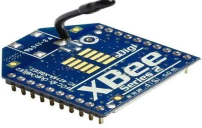
This is the new 2.4GHz XBee XB24-BWIT-004 module from Digi as shown in figure 3. Series 2.5 improves on the power output and data protocol. These modules take the 802.15.4 stack (the basis for Zigbee) and wrap it into a simple to use serial command set. These modules allow a very reliable and simple communication between microcontrollers, computers, systems, really anything with a serial port! Point to point and multi-point networks are supported.
ZigBee is an IEEE 802.15.4-based specification for a suite of high-level communication protocols used to create personal area networks with small, low-power digital radios, such as for home automation, medical device data collection, and other low-power low-bandwidth needs.The technology defined by the ZigBee specification is intended to be simpler and less expensive than other wireless personal area networks (WPANs), such as Bluetooth or Wi-Fi. Applications include wireless light switches, electrical meters with in-home-displays, traffic management systems, and other consumer and industrial equipment that requires short-range low-rate wireless data transfer.
F. RADIO FREQUENCY IDENTIFICATION READER
A radio frequency identification reader (RFID reader) is a device used to gather information from an RFID tag, which is used to track individual objects. Radio waves are used to transfer data from the tag to a reader.
RFID is a technology similar in theory to bar codes. However, the RFID tag does not have to be scanned directly, nor does it require line-of-sight to a reader. The RFID tag it must be within the range of an RFID reader, which ranges from 3 to 300 feet, in order to be read. RFID technology allows several items to be quickly scanned and enables fast identification of a particular product, even when it is surrounded by several other items.RFID tags have not replaced bar codes because of their cost and the need to individually identify every item.
To read the information encoded on a tag, a two-way radio transmitter-receiver called an interrogator or reader emits a signal to the tag using an antenna. The tag responds with the information written in its memory bank. The interrogator will then transmit the read results to an RFID computer program. With one pass of the handheld RFID reader, the associate can not only find a specific pair, but they can tell how many of each pair are on the shelf and which pairs need to be replenished. The associate can learn all of this information without having to scan each individual item.
V. SOFTWAREPROGRAMMINGALGORITHM
Step 1: START after system reset. Step 2: Initialize system and all module. Step 3: Select type of disability.
Step 4: Read all sensor data and send it to master controller via zigbee module. Step 5: Compare the data with predefined values.
Step 6: Check the Condition:
If (value != predefined)
Then{Give alert to user according to disability selected
Execute the commands as instructed by master controller Do changes as per command}.
Step 7: If condition not satisfied then go to step 4. Step 8: End.
VI.CONCLUSION AND FUTURE WORK
The existing smart home monitoring and control systems which are mostly used do not accommodate special needy users to manage their home appliances. A wireless sensor network based system for smart home automation was designed, built and tested to address such missing functionality. The system is customized to provide the special need residents with tools and services to monitor and operate home appliances remotely. The implemented system provides home residents with disabilities to take advantage of the advancement in technology. It enables them to perform their daily activities by remotely monitoring and controlling their home appliances without having to depend on others. The system is programmed so that it can be configured to adjust to the customer’s disability providing them with better and convenient lifestyle. The system is scalable and can be extended to include more and different services and tools. The system is portable, compact, affordable and easy to use. The system can be modified using more efficient communication protocol and VLSI design for more faithful operation.
REFERENCES
1. RaafatAburukba, A. R. Al-Ali, NourhanKandil, DialaAbuDamis, “Configurable ZigBee-based Control System for People with Multiple Disabilities in Smart Homes”, 978-1-4673-8743-9/16/$31.00 ©2016 IEEE
2. Vinay sagar K N1,Kusuma S M2, “Home Automation Using Internet of Things”, International Research Journal of Engineering and Technology (IRJET) e-ISSN: 2395 -0056 Volume: 02 Issue: 03 | June-2015
4. Basma M. Mohammad El-Basioni1 , Sherine Mohamed Abd El-Kader2 , and Hussein S. Eissa3, “Independent Living for Persons with Disabilities and Elderly People Using Smart Home Technology”, International Journal of Application or Innovation in Engineering & Management (IJAIEM) Volume 3, Issue 4, April 2014
5. D.NARESH1, B.CHAKRADHAR2, S.KRISHNAVENI3, “Bluetooth Based Home Automation and Security System Using ARM9”, International Journal of Engineering Trends and Technology (IJETT) – Volume 4 Issue 9- Sep 2013
6. R.A.Ramlee, D.H.Z.Tang, M.M.Ismail, “Smart Home System for Disabled People Via Wireless Bluetooth” . 2012
7. Jer-Vui Lee, Yea-DatChuah and Kenny T.H. Chieng“Smart Elderly Home Monitoring System with an Android Phone” 2013 Vol. 7, No. 3, May, 2013
8. SafiyyaRusli, MehrdadDianati“Mobile Access to Smart Home Network”2012
9. Malik Sikandar Hayat Khiyal, Aihab Khan, and ErumShehzadi“SMS Based Wireless Home Appliance Control System (HACS) for Automating Appliances and Security” 2009 IJAIR
10. Md. RaihaanKamarudin., Md. Aiman F. Md. Yusof. “Low Cost Smart Home Automation via Microsoft Speech Recognition” 2013 IJENS Vol: 13 No: 03
11. Z. Zenn Bien, Jun-Hyeong Do, Jung-Bae KimKwang-Hyun Park and DimitarStefanov“User-friendly interaction/interface control of intelligent home for movement-disabled people”
12. T. Kirankumar, B. Bhavani“A Sustainable Automated System for Elderly People Using Voice Recognition and Touch Screen Technology, IJSR 2013
13. Shriram K Vasudevan,SivaramanR,SubashriV,Murali N “ Design and Development of an Embedded System for Monitoring the Health Status of a Patient” 2013