ABSTRACT
GOLI, KIRAN KUMAR. Functional Coatings Based on Denaturation and Adsorption of Proteins. (Under the direction of Jan Genzer and Orlando Rojas.)
We have developed a novel method for the modification and functionalization of hydrophobic polymeric surfaces. This method offers a simple and versatile platform that is alternative to the commonly used flame, corona, plasma and other types of treatments. Specifically, denatured protein molecules were physisorbed on hydrophobic surfaces including flat solid surfaces modified with self-assembled n-octadecyltrichlorosilane (ODTS) hydrophobic layers and polypropylene (PP) materials through nonspecific interactions followed by cross-linking the adsorbed proteins forming a stable coating. Protein denaturation and properties of adsorbed protein layers were characterized by using analytical techniques including circular dichroism, ellipsometry, contact angle, and Fourier transform infrared spectroscopy in the attenuated total reflection mode. The amount of protein adsorbed on the surface was adjusted by the means of protein denaturation (chemical or thermal), varying pH and protein concentration in the deposition solution, and adsorption time. The inherent hydrophilic amino acid functionalities of the protein layer including hydroxyl and amino groups endowed surfaces with improved wettabilities. The protein primers also provided opportunity to create/generate new functional coatings for selected applications, which involve growing polymeric grafts and attaching silver nanoparticles.
protein. Our work established that these amphiphilic coatings suppressed significantly the adsorption of proteins as compared to PP surfaces or PP surfaces coated with parent PHEMA brushes. Modulation of the surface composition of the top-most layer of the amphiphilic coating and its anti-fouling capability is evident by varying the type of the fluorinated unit grafted to PHEMA.
Functional Coatings Based on Denaturation and Adsorption of Proteins
by
Kiran Kumar Goli
A dissertation submitted to the Graduate Faculty of North Carolina State University
in partial fulfillment of the requirements for the degree of
Doctor of Philosophy
Materials Science and Engineering
Raleigh, North Carolina 2012
APPROVED BY:
_______________________________ ______________________________ Jan Genzer Orlando Rojas
Chair of Advisory Committee Co-chair of Advisory Committee
________________________________ ________________________________ Anatoli Melechko Behnam Pourdeyhimi
DEDICATION
BIOGRAPHY
ACKNOWLEDGEMENTS
First and foremost, I would like to thank my advisors, Professors Jan Genzer and Orlando Rojas for giving me the opportunity to be their student. I have worked with Dr. Genzer for four years; he has been an excellent mentor and it has been a great learning experience. His valuable guidance, support and encouragement throughout my research helped to improve myself professionally and contribute to the scientific community. This dissertation work would have never been accomplished without the valuable guidance and support of Professor Rojas.
I thank Professors Anatoli Melechko, Behnam Pourdeyhimi and Tzy-Jiun Luo for serving on my dissertation committee and also for their support and guidance that made my work a success (in addition to being extremely helpful and supportive). Also, I would like to thank Professors John van Zanten, Balaji Rao, Orlin Velev, Michael Dickey, Saad Khan, Joseph Tracy, Simon Lappi, Driss Elhanafi and Christopher Gorman for allowing me to use several lab facilities in their lab and for their insightful advice. I wish to acknowledge the financial support of this research by the Nonwoven Cooperative Research Center (NCRC). I am extremely thankful to current and former group members of Dr. Genzer’s research group for their invaluable support and help throughout this journey. Many thanks also to the research group members of Orlando Rojas, Orlin Velev, Saad Khan, Michael Dickey and Gregory Parsons for help with various experiments. Special thanks to Edwin Walker, Julie Albert, Casey Galvin, Xiaomeng Liu, Nimish Gera, Amit Naik, Alexander Richter and Amar Kumbhar for going out of their way to help me with my research efforts. Thanks to the staff in the Materials Science and Engineering and Chemical and Biomolecular Engineering departments for their support.
TABLE OF CONTENTS
LIST OF TABLES ... x
LIST OF FIGURES... xi
CHAPTER 1 - INTRODUCTION ... 1
1.1. Surface modification techniques ...5
1.1.1. Flame treatment ... 5
1.1.2. Corona discharge ... 5
1.1.3. Plasma treatment ... 6
1.1.4. UV light treatment ... 10
1.1.5. Other surface treatments ... 11
1.2. Surface modification by physical deposition of monolayers or thin films ... 13
1.2.1. Formation of polyelectrolyte multilayers by layer-by-layer (LbL) self-assembly 13 1.2.2.Formation of thin films by Langmuir-Blodgett (LB) technique ... 13
1.2.3. Formation of block copolymer thin films... 14
1.3. Functionalization based on denaturation and adsorption of proteins ... 14
1.3.1. Protein adsorption ... 14
1.3.2. Proteins ... 15
1.3.3. Protein structures ... 16
1.3.4. Protein-surface interactions ... 18
1.3.5. Thermodynamics of protein adsorption ... 21
1.3.6. Kinetics of protein adsorption ... 22
1.3.7. Characterization of surface properties ... 23
1.3.8. Characterization of denatured proteins ... 23
1.4. Applications of denatured proteins ... 25
CHAPTER 2 - GENERATION OF FUNCTIONAL COATINGS ON HYDROPHOBIC SURFACES THROUGH DEPOSITION OF DENATURED
PROTEINS FOLLOWED BY GRAFTING FROM POLYMERIZATION ... 50
2.1. Abstract ... 50
2.2. Introduction ... 51
2.3. Materials and Methods ... 55
2.3.1. Materials ... 55
2.3.1. Hydrophobic ODTS layers assembled on silicon wafers ... 55
2.3.2. Denaturation and adsorption of proteins ... 56
2.3.3. Circular dichroism of protein solutions ... 57
2.3.4. Cross-linking of adsorbed protein coatings and their stability. ... 57
2.3.5. Formation of polyelectrolyte layers. ... 58
2.3.6. Immobilization of ATRP initiator on protein-coated surfaces. ... 58
2.3.7. Preparation of PHEMA brushes on modified surfaces via ATRP. ... 58
2.3.8. Ellipsometry ... 59
2.3.9. Contact angle measurements. ... 59
2.3.10. Fourier transform infrared spectroscopy. ... 60
2.3.11. Atomic force microscopy. ... 60
2.4. Results and Discussion ... 60
2.4.1. Urea and thermal denaturation of proteins. ... 60
2.4.2. Adsorption of urea-denatured proteins. ... 62
2.4.3. Adsorption of thermally-denatured proteins... 64
2.4.4. Cross-linking and stability of protein coatings ... 66
2.4.5. Deposition of polyelectrolyte layers and surface-initiated ATRP of polymer brushes. ... 67
2.4.6. Morphologies of LYS and PHEMA-coated ODTS layers. ... 70
2.4.7. Modification of hydrophobic fibers. ... 70
2.5. Conclusions ... 71
CHAPTER 3 - FORMATION AND ANTIFOULING PROPERTIES OF
AMPHIPHILIC COATINGS FORMED ON POLYPROPYLENE FIBERS ... 88
3.1 Abstract ... 88
3.2 Introduction ... 89
3.3 Materials and Methods... 91
3.3.1. Materials ... 91
3.3.2. Preparation of protein solution and deposition on surfaces ... 92
3.3.3. Formation of amphiphilic polymer brush layers... 92
3.3.4. Ellipsometry ... 93
3.3.5. Contact angle measurements ... 94
3.3.6. X-ray photoelectron spectroscopy ... 94
3.3.7. Fourier transform infrared (FTIR) spectroscopy ... 94
3.3.8. Atomic force microscopy (AFM) ... 95
3.3.9. Confocal Microscopy ... 95
3.4. Results and Discussion ... 96
3.4.1. Adsorption of denatured proteins onto ODTS and PP surfaces ... 96
3.4.2. Formation of amphiphilic polymeric brushes ... 97
3.5. Conclusions ... 103
3.6. References ... 104
CHAPTER 4 - GENERATION AND PROPERTIES OF ANTIBACTERIAL COATINGS BASED ON ELECTROSTATIC ATTACHMENT OF SILVER NANOPARTICLES TO PROTEIN-COATED POLYPROPYLENE FIBERS ... 117
4.1. Abstract ... 117
4.2. Introduction ... 118
4.3. Materials and Methods ... 120
4.3.1. Materials ... 120
4.3.2. Preparation of silver nanoparticles ... 120
4.3.3. Adsorption of denatured protein solutions on PP nonwoven surfaces ... 121
4.3.5. Antibacterial activities of silver nanoparticle treated PP nonwovens: ... 122
4.3.6. Ultraviolet-visible (UV-vis) analysis ... 123
4.3.7. Transmission electron microscopy (TEM) ... 123
4.3.8. Zeta potential analysis ... 124
4.3.9. Scanning electron microscopy (SEM) ... 124
4.4. Results and discussion ... 124
4.4.1. Preparation of silver nanoparticles at different molar concentrations ... 124
4.4.2. Deposition of silver nanoparticles on protein-coated PP nonwoven surfaces ... 126
4.5. Conclusions ... 130
4.6. References ... 131
CHAPTER 5 - SUMMARY AND OUTLOOK ... 149
5.1. Summary ... 149
5.2.Outlook ... 151
5.2.1. Effect of adsorption time on protein coverage ... 151
5.2.2. Protein denaturation using extreme solution conditions and different chemical denaturants ... 152
5.2.3.Spray-assisted protein adsorption ... 153
5.2.4. Protein adsorption from organic solvents and co-solvents ... 154
5.2.5. Grafting of polymers using free-radical polymerization ... 154
5.2.6. Formation of amphiphilic polymers on poly(ethylene terephthalate) (PET) surfaces ... 155
5.2.7. Molecular weight determination of surface grafted polymer brushes ... 156
5.2.8. Patterning of surface grafted polymer brushes ... 158
5.3. References ... 160
APPENDICES ... 168
APPENDIX A - SUPPORTING INFORMATION FOR CHAPTER 2 ... 169
A.1. Fractional surface coverage of proteins ... 169
A.3. XPS analysis of immobilized ATRP Initiator (2-BPB) ... 170
A.4. Deposition of polyelectrolyte layer and surface initiated ATRP of polymer (PNIPAAm) brushes. ... 171
A.5. References ... 173
APPENDIX B - SUPPORTING INFORMATION FOR CHAPTER 3... 179
B.1. Relating ellipsometry thickness with chemical composition of P(HEMA-co-fHEMA) ... 179
B.2. FT-IR spectroscopy of LYS-modified PP nonwoven ... 180
B.3. FT-IR spectroscopy of FIB-modified ODTS flat surfaces ... 181
B.4. References ... 182
APPENDIX C - SUPPORTING INFORMATION FOR CHAPTER 4 ... 187
C.1. Determination of the reduction of Ag+ to Ag0 ... 187
C.2. Determination of the molar concentration of silver nanoparticles (C) in solutions... 187
LIST OF TABLES
Table 1.1. Strengths of different bonds in tertiary protein structure. ... 35
Table 1.2. Protein classification based on internal structure stability. ... 36
Table 1.3. Protein adsorption based on nature of proteins. ... 37
Table 1.4. Protein adsorption based on nature of surfaces... 38
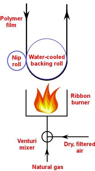
Table 1.5. Enthalpy of protein adsorption on different surfaces. ... 39
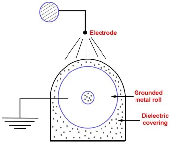
Table 1.6. Characterization techniques for studying surface properties. ... 40
Table 1.7. Characterization techniques for studying the adsorption process and the protein-coated surfaces... 41
Table 3.1. IR vibrations in PP and functionalized PP fiber materials. ... 106
Table 4.1. Molar concentrations of silver nanoparticles with different initial concentrations of silver nitrate. ... 134
Table 4.2. Antibacterial activity of the PP nonwoven surfaces before and after modification with proteins and silver nanoparticle coating. ... 135
Table 5.1. Optimal conditions for digestion of LYS from enzymes. ... 162
Table A.1. Chemical composition (atom % C, O, N and Br) on different surfaces. ... 174
Table B.1. Chemical composition of fHEMA in P(HEMA-co-fHEMA) developed on LYS-coated ODTS surface. ... 183
Table B.2. Chemical composition of fHEMA in P(HEMA-co-fHEMA) developed on FIB-coated ODTS surface. ... 184
LIST OF FIGURES
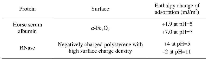
Figure 1.1. Schematic diagram of flame treatment device. ... 42
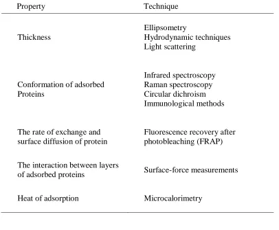
Figure 1.2. Schematic diagram of corona discharge manifold. ... 43
Figure 1.3. Schematic representation of corona modified polymeric PP surfaces... 44
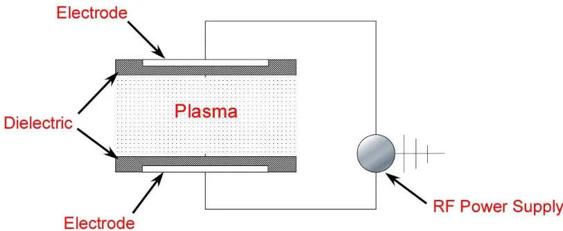
Figure 1.4. Schematic set-up of atmospheric pressure plasma treatment device. ... 45
Figure 1.5. Schematic illustration depicting the interaction of protein molecules of varying sizes with a surface. ... 46
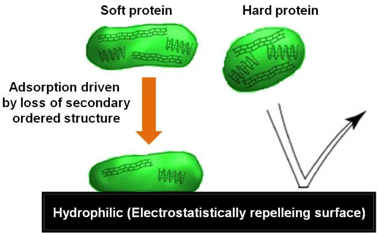
Figure 1.6. Schematic depicting the behavior of soft and hard proteins on electrostatically repelling surface. ... 47
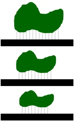
Figure 1.7. Effect of protein concentration in the bulk solution on conformational changes of protein structures on surfaces. ... 48
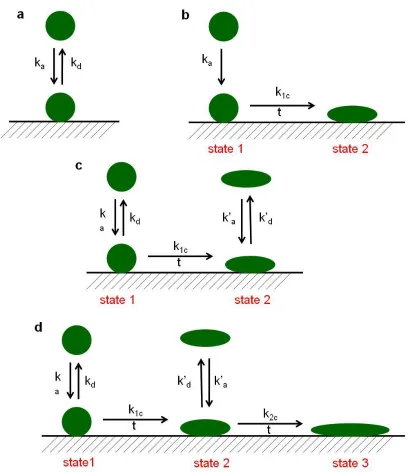
Figure 1.8. Models depicting protein adsorption according to a) Langmuir, b) Lundström, c) Beissinger and Leonard, and d) Soderquist and Walton; k is the rate constant, subscript a, d, 1c and 2c are adsorption, desorption, conformation changes during transformation from state 1 to state 2 and conformational changes during tansformation from state 2 to state 3. ... 49
Figure 2.1. Schematic representation of protein denaturation in solution and its subsequent deposition on a hydrophobic substrate. The latter process results in the formation of a coating layer whose surface is comprising predominantly hydrophilic moieties present originally in the corona section of a native protein. ... 77
Figure 2.3. Ellipticity at 222 nm determined from CD spectra of thermal denatured LYS and FIB protein solutions as a function of increased temperature. ... 79 Figure 2.4. Ellipsometry (top) and DIW contact angle (bottom) profiles of urea-denatured
protein coatings on ODTS surfaces at various bulk concentrations of denatured proteins. The horizontal dotted line in the bottom spectrum denotes the wettability of ODTS... 80 Figure 2.5. Ellipsometry (left) and DIW contact angle (right) profiles of parent/native (black
squares) and thermally-denatured (red circles and green triangles) LYS protein coatings on ODTS surfaces at various bulk concentrations. ... 81 Figure 2.6. Ellipsometry (top) and DIW contact angle (bottom) profiles of thermally
denatured LYS and soy (7S & 11S) protein coatings on ODTS surfaces at various bulk concentrations. ... 82 Figure 2.7. a) Ellipsometry (top) and b) DIW contact angle (bottom) profiles of thermally
denatured LYS layers on ODTS surfaces after stability studies. The DIW contact angle of ODTS is 108. ... 83 Figure 2.8. Schematic depicting built-up of protein and polyelectrolyte layers followed by
subsequent ATRP polymerization of PHEMA brushes. In method (i) the 2-BPB initiator is attached directly to the cross-linked FIB protein layer. In methods (ii) and (iii), 2-BPB gets anchored to substrates comprising a single (i.e., PAH1)
or a multilayer (i.e., PAH1/PSS/PAH2), respectively, of polyelectrolytes
deposited by the LbL method on top of protein primer. ... 84 Figure 2.9. (top row) Dry thickness (left) and DIW contact angle (right) of PHEMA brushes
(i)-(iii) denoted pictorially in Figure 8 are shown in the top row. The data corresponding to LYS protein primer are shown in the bottom row. For clarity the order in the DIW data have been reversed relative to that of the thickness. . 85 Figure 2.10. AFM images, 3 × 3 µm2, of control ODTS (left), LYS-coated ODTS (middle)
and PHEMA-coated ODTS (right) surfaces. ... 86 Figure 2.11. FTIR spectra collected in transmission from (from bottom to top) PP nonwoven
sheet (black), PP-sheet coated with denatured fibrinogen (FIB) layer (olive) and PP-FIB fiber with PHEMA brushes (orange). ... 87 Figure 3.1. Schematic illustration depicting the steps leading to the formation of amphiphilic
fiber mats. A polypropylene (PP) nonwoven sheet is exposed to the solution of denatured protein and subsequently cross-linked with glutaraldehyde (GA) and NaBH4. After depositing 2-bromopropinoyl bromide (2-BPB), poly(hydroxyethyl methacrylate) (PHEMA) brushes were formed by ATRP of 2-hydroxyethyl methacrylate (HEMA). Subsequent post-polymerization modification (PPM) with fluorinated agents resulted in P(HEMA-co-fHEMA) amphiphilic random copolymer grafts. Similar surface modification sequence was applied to ODTS surfaces. ... 107 Figure 3.2. Schematic illustration of chemical modification of PHEMA brushes with
trifluoroacetic anhydride (F1), heptafluorobutyryl chloride (F3), and pentadecafluoro-octanoyl chloride (F7) leading to the formation of amphiphilic random copolymers of P(HEMA-co-fHEMA), i.e., PHEMA-F1, PHEMA-F3, and PHEMA-F7, respectively. ... 108 Figure 3.3. FTIR spectra collected in transmission mode (from bottom to top) on PP
Figure 3.4. Tapping mode atomic force microscope (AFM) topography images taken from ODTS after functionalization with PHEMA and P(HEMA-co-fHEMA) with three different mesogens in dry state. The PHEMA samples were fabricated utilizing “grafting from” polymerization from denatured lysozyme (top row) and fibrinogen (bottom row) coating on ODTS SAMs using methodological steps described in the text. ... 110 Figure 3.5. (top) Ellipsometric dry thickness of parent PHEMA brushes (orange) and the
corresponding thickness increase after fluorination of PHEMA with various fluorinating agents (green). The experiments were performed on two types of denatured protein-based substrates: lysozyme (LYS) and fibrinogen (FIB). (bottom) Corresponding mole fraction of the fluorinated HEMA segments in P(HEMA-co-fHEMA) brushes as determined from the ellipsometric data using a simple analytical model described in the Appendix B. ... 111 Figure 3.6. XPS atomic surface concentration obtained at two different take-off angles for
carbon, oxygen, fluorine and silicon, collected from PHEMA brushes and PHEMA brushes fluorinated with F1, F3, or F7 grown from LYS supports. ... 112 Figure 3.7. Advancing (squares) and receding (circles) contact angles measured using
deionized water (DIW) from P(HEMA-co-fHEMA) brushes prepared by fluorinating PHEMA brushes with F1, F3 and F7, as described in the text. The experiments were performed on two types of denatured protein-based substrates: lysozyme (LYS) and fibrinogen (FIB). ... 113 Figure 3.8. Schematic illustration depicting the spatial distribution of F1, F3, and F7
fluorinating species inside P(HEMA-co-fHEMA) brushes. ... 114 Figure 3.9. Merged optical microscopy and fluorescence microscopy images collected from
PHEMA), and after fluorination of PHEMA with F1, F3, and F7 (PP-LYS-PHEMA-Fx, bottom row). ... 115 Figure 3.10. Merged optical microscopy and fluorescence microscopy images collected from
fibers exposed to FITC-labeled BSA solutions. The fibers included bare polypropylene (PP), PP after coating with denatured layer of fibrinogen (PP-FIB), PP-FIB fibers after “grafting from” polymerization of HEMA PHEMA), and after fluorination of PHEMA with F1, F3, and F7 (PP-FIB-PHEMA-Fx, bottom row). ... 116 Figure 4.1. UV-visible spectra of silver nanoparticles prepared in aqueous solutions at four
different molar concentrations of AgNO3; (a) xAg = 0.25 mM, (b) xAg = 0.5 mM,
(c) xAg = 1.0 mM and (d) xAg = 2.0 mM. ... 136
Figure 4.2. Photographs of solutions containing AgNPs synthesized with different molar concentrations of AgNO3 represented by (a) xAg = 0.25 mM, (b) xAg = 0.5 mM,
(c) xAg = 1.0 mM and (d) xAg = 2.0 mM. A variation in visible color can be seen
with increasing molar concentrations of (a)-(d). ... 137 Figure 4.3. TEM images of silver nanoparticles prepared from molar concentrations of
AgNO3; (a) xAg = 0.25 mM, (b) xAg = 0.5 mM, (c) xAg = 1.0 mM and (d) xAg =
2.0 mM. ... 138 Figure 4.4. Size distribution histograms of AgNPs prepared from molar concentrations of
AgNO3; (a) xAg = 0.25 mM, (b) xAg = 0.5 mM, (c) xAg = 1.0 mM and (d) xAg =
2.0 mM. ... 139 Figure 4.5. Schematic illustration of the adsorption of denatured protein layers on PP
nonwoven surfaces. Pictures were not drawn on proportional scales (in reality, size of lysozyme is much smaller than diameter of the nonwoven fiber). ... 140 Figure 4.6. IR spectra of untreated PP and PP modified with LYS. ... 141
scales (in reality, size of lysozyme is much smaller than diameter of the nonwoven fiber). ... 142 Figure 4.8. Protein modified PP nonwovens coated with silver nanoparticles. The sample
dimensions are 3 x 3 cm2. ... 143 Figure 4.9. UV-visible absorbance spectra of PP-LYS (1.1) nonwoven (black), silver
nanoparticle coated PP-LYS with varying amounts of proteins; PP-LYS (black), LYS(0.44)-AgNPs (blue), LYS(0.75)-AgNPs (magenta) and PP-LYS(1.1)-AgNPs (olive greeen). ... 144 Figure 4.10. SEM images of the control PP and protein-coated PP nonwovens after treatment
with silver nanoparticles. ... 145 Figure 4.11. LB plates corresponding to the E.coli suspension recovered from control and
treated PP nonwovens. The colonies on the plates were counted and the percent killing efficiency is reported in Table 4.2. ... 146 Figure 4.12. The antibacterial activity of control PP and silver nanoparticle treated PP
nonwoven mats. Zone of inhibition (ZOI) can be observed around the silver nanoparticle treated mats and are shown at the top right corner of the plates. The sample dimensions are 2 x 2 cm2. The images at the bottom of petri dish show the corresponding enlarged optical microscopy images taken at the edge of nonwoven mat. ... 147 Figure 4.13. Antibacterial efficiency of silver nanoparticle deposited PP surfaces calculated
from test method (b) with increasing amount of protein on the surface. ... 148 Figure 5.1. Ellipsometry profiles of urea-denatured protein coatings on PET spin-coated flat
surfaces... 163 Figure 5.2. Schematic illustrating the generation of orthogonal gradients from the
combination of two linear gradients whose properties are perpendicular to each to other. ... 164 Figure 5.3. Schematic illustrating the digestion of protein layer in the presence of an enzyme
Figure 5.4. Schematic depicting the technological steps for the formation of polymer patterns based on surface topography. ... 166 Figure 5.5. Schematic depicting the technological steps for the formation of polymer patterns
based on surface chemistry. ... 167 Figure A.1. SDS-PAGE of LYS and LYS proteins cross-linked in the presence of GA with
NaBH4 at different pH conditions. ... 175 Figure A.2. Immobilization of ATRP initiator to cross-linked protein-coated ODTS surfaces. ... 176 Figure A.3. XPS spectra of (from bottom to top) ODTS (black), ODTS surface coated with
denatured fibrinogen (FIB) layer (green), ODTS-FIB surface immobilized with BPB (dark purple), and ODTS/cross-linked-FIB surface immobilized with 2-BPB (magenta). The inset shows magnification of the spectra at approximately 70 eV. ... 177 Figure A.4. (top row) Dry thickness (left) and DIW contact angle (right) from PNIPAAm
brushes grown from functional layers deposited on top of flat ODTS/FIB-coated silica substrates. The layer comprising denatured FIB was cross-linked with GA/NaBH4. (bottom row) Dry thickness (left) and DIW contact angle (right)
from PNIPAAm brushes grown from functional layers deposited on top of flat ODTS/LYS-coated silica substrates. The layer comprising denatured LYS was cross-linked with GA/NaBH4. Data corresponding to fabrication methods
(i)-(iii) denoted pictorially in Figure 2.8 in the Chapter 2 are shown in the top row. Note that in the method (iii) we only use a bilayer PSS/PAH for the ODTS/LYS substrate. The data corresponding to LYS protein primer are shown in the bottom row. For clarity the order in the DIW data have been reversed relative to that of the thickness. ... 178 Figure B.1. FTIR spectra collected in transmission mode (from bottom to top) on PP
PP-LYS-PHEMA modified with various fluorinated agents (green), i.e., F1, F3, or F7, similar to Figure 3.3. ... 185 Figure B.2. FTIR spectra collected in ATR mode for flat ODTS surfaces modified with FIB
CHAPTER 1 -
INTRODUCTION
useful for many practical applications in industry as it creates materials with tailor-made coating properties.
Many physical and chemical modification methods have been reported in the literature to optimize the surface properties of polymers. Physical modification involves the exposure of surfaces to environments that contain active species such as free radicals, electrons, ions, excited molecules or electromagnetic radiation.6 These active species attacks and reacts with the polymer surface molecules and generate (typically oxygen-containing) polar and reactive groups on the treated surfaces.7 The most common physical modification methods include treatments by flame, corona, plasma, UV, ozone, combined UV/ozone (UVO), electron beams, ion beams, and γ-rays. In general, physical treatments do not involve hazardous chemicals; hence these methods are typically environmentally safe, relatively clean, and engage relatively short processing times.8 Chemical modification techniques include grafting of small hydrophilic units, chemical treatments (such as oxidation by strong acids), deposition of self-assembled monolayers (SAMs), grafting of macromolecules or polymerization processes that are initiated directly on the surface of said material. Alternatively, surface modification can be achieved by the adsorption of surface active amphiphiles (i.e., copolymers or surfactants)9 or by pre-mixing (melt-blending) polymer precursors with surface-active agents (i.e., alkyl alcohol ethoxylates) during manufacturing processes, which segregate to the surface of the initially hydrophobic films or fibers.10 In many cases, a combination of physical and chemical methods must be employed to achieve desired coatings.6 Such reactions involve grafting polymer chains on the substrate surface pre-activated via plasma or glow discharge, corona discharge or UV light.
The main objective of this Ph.D. thesis is to devise a novel and versatile surface modification technology to impart hydrophilic and functional characteristics by denaturation and adsorption of proteins on hydrophobic polymer surfaces. Flat hydrophobic n-octadecyltrichlorosilane (ODTS) and PP nonwoven substrates are used to immobilize the denatured protein molecules. In general, proteins in aqueous solutions adopt folded “micelle-like” structures with hydrophobic amino acid residues found predominantly in their interior, while the hydrophilic amino acid residues are found on the surface of folded proteins. Denatured protein molecules obtained by adding urea exposed more hydrophobic amino acids (which are protected in the interior of the core of native proteins) to the exterior provided more sites for binding of proteins onto hydrophobic surfaces. Adsorption of these unfolded protein molecules on ODTS surfaces occurs preferentially with hydrophobic amino acid residues partitioning on hydrophobic surfaces while the hydrophilic amino acid residues are present on the periphery of the protein layer. The inherent hydrophilic amino-acid functionalities of the protein layer including hydroxyl and amino groups as well as the charged groups on the surface are subsequently utilized to introduce desired functionalities by anchoring functional polymer grafts, amphiphilic polymer grafts or depositing silver nanoparticles for application ranging from improved wettabilities to antibacterial properties.
Proteins represent an interesting class of coating materials to create hydrophilic surfaces because they adsorb through non-specific interactions on hydrophobic surfaces without involving any harsh treatments. Denaturation of protein molecules is desired to make the hydrophobic residues available for adsorption on hydrophobic surfaces. This can be accomplished by chemical (i.e., using urea) or thermal means in the bulk solution, and can be monitored by various methods, such as circular dichroism. The amount of urea and heat-denatured proteins adsorbed is monitored for depositions at varying conditions, including, protein concentration in solution, pH, adsorption time, and temperature. Adsorbed protein molecules are subsequently used as primers to graft polymer brushes by surface-initiated atom-transfer radical polymerization of selected monomers. The resultant properties of protein and polymer layers such as thickness, wettability, surface chemical changes and surface morphology are explored and the results are discussed.
negative bacteria, Escherichia Coli. Chapter 5 proposes potential approaches and insights towards the advancement of this facile and robust technology to diverse applications.
1.1. Surface modification techniques
This section offers a brief overview of the most conventional and current surface modification techniques used to alter surface properties of polymers. This section also points out the reasons and motivation for the development of a novel, facile and robust surface modification technology.
1.1.1. Flame treatment
Flame treatment was developed in the 1950s to improve the wetting and adhesion properties of polyolefin films.14 A schematic diagram for a flame treatment set-up is shown in Figure 1.1. In this method, one side of the polymer film to be treated is exposed to the burner while the backside is cooled by water-cooled backing roll. The burners are fed with a mixture of natural gas and air flame in controlled ratios to oxidize the polymer surfaces. Free radicals, such as OH and atomic oxygen, present in the flame primarily attack the tertiary carbon atom of the PP parent/backbone leading to the formation of polymer-radicals which would react with O, -OH and O2 species. This treatment results in the generation of
oxygen-containing species such as hydroxyls, carboxyls, and carbonyl functionalities on the polymer surfaces. Flame treatment is used extensively to treat paperboard or thick polyolefin materials, such as blow-molded bottles by increasing the number of burners. Typical exposure times of the films to the flames must be less than 1 s. The difficulty in controlling the chemical composition of fuel and the distance between the tip of the flame and the object results in inconsistent treatments.8,14,15
1.1.2. Corona discharge
primary method of treating films in comparison to flame treatments due to the safety concerns related to open flames in industrial environments.14 A schematic of corona treatment system is depicted in Figure 1.2. High frequency electrical energy is used to generate the electrical discharge in a gap between two electrodes under atmospheric pressure. The electrical field generated excites the gas molecules (air) and dissociates some of them thus generating ions, radicals, electrons, and ozone, which reacts with the surface polymer molecules (of the film that is passed on the roll during the treatment processes) forming radicals. These radicals react rapidly with the atmospheric oxygen as shown in Figure 1.3, leading to the introduction of polar oxygen atoms (mainly, peroxide or carboxylic groups).4,8 The exposure times of the films to the corona were fractions of seconds depending upon the energies supplied.15 Corona pre-treated PE films can be grafted with various water polymers such as poly(acrylic acid) to introduce new functional properties as reported in previous works.3 Elsabee et al.16 activated PP films with corona-discharge to generate peroxide and carboxylic acids which were used to attach chitosan, thus imparting antimicrobial properties.
The equipment set-up of both flame and corona treatments are simple, cost-effective and can be used in continuous operations at high processing speeds. However, since both the treatments are carried out under ambient conditions, the resultant treatment may be inconsistent due to the difficultly in controlling temperature, humidity or contaminants in the atmosphere. In addition, prolonged exposures lead to the degradation of polymers. Another limitation is that the enhanced surface properties are short-lived, therefore further applications or bonding processes such as printing, adhesion or sealing must be carried out immediately.8,14,15
1.1.3. Plasma treatment
temperatures, in which gas species are ionized by the glow discharge producing ions, electrons, radicals and excited molecules.8 The polymer surfaces that come in contact with gas plasma are bombarded by this energetic species generating various functional groups such as –COOH, –OH, and –NH2 depending upon the nature of treatment gases used. The
most commonly used non-polymerizable treatment gases are air, oxygen, argon, hydrogen, ammonia, argon/ammonia and fluorine. In comparison to conventional flame and corona treatments, plasma treatments offer several advantages listed below: 8,18,2
1. Can be confined to the top surface layer with depths typically ranging between 0.005 to 0.05 µm, thereby not damaging the bulk properties.
2. Introduce diverse chemical functionalities onto polymer surfaces by variation of the treatment gas used.
3. Modifies polymer surfaces, irrespective of the structure or chemical reactivity of the surfaces.
4. Operate at lower temperatures (relative to corona or flame treatments), which helps in modifying heat-sensitive polymeric materials.
5. Relatively long-lived (in comparison to flame and corona). 6. Provide fairly uniform modification throughout the substrates.
functionalization or must be stored in a sealed container before they can be treated with further functionalization.18,19 Petasch et al.20 reported on a considerable improvement in bond strengths of low-density polyethylene (LDPE) and PP and poly(ethylene terephthalate) (PET) films after treatment with O2 plasma due to the generation of polar functional groups
at the surface layer. O’Kell et al.21
explored the effect of air and nitrogen plasma-treatments on peel strengths of aluminum/PE/aluminum laminates. They reported a significant increase in peel strength of PE/aluminum interface for air plasma-treated samples as compared to nitrogen plasma-treated substrates. This is most likely due to the better adhesion provided by the oxygen-containing functional groups added to the PE surface during the air-plasma modification. In addition to generating functional groups on polymer surfaces, cross-links can be created on the surface to improve the barrier properties of polymers. A relevant work of Rossi et al.22 on Ar plasma-modified LDPE films showed an increase in O2, CO2 and N2
barrier properties due to the cross-linking induced over the polymer surfaces. Guruvenket et al.23 modified the polystyrene and polyethylene films using oxygen and argon plasmas. They observed a significant improvement in wettabilities of oxygen and argon-treated polymers. In the former case, higher degrees of surface hydrophilicities were evident due to the occurrence of simultaneous processes. Atomic oxygen and other active species from the plasma reacted with surface carbon atoms of the polymer surface resulted in the formation of volatile reaction products and oxygen containing functional groups. However, in the latter case, the active species from argon plasmas abstracted hydrogen atoms from the polymer surface and generated free radicals. These radicals interacted with other radicals and formed cross-links and unsaturated groups with chain scission resulting in surface modification.
discharge ionizes these monomers followed by their deposition on polymer surfaces. Plasma polymerization is considered to be a very effective technique to grow a thin layer of a surface coating in a single-step process that may endow polymer surfaces with a permanent finish.8 However, the structure resulting from plasma-polymerized films is not well-defined as it differs from the structure produced by conventional polymerization schemes using the same monomer In addition the control over surface chemistry of the produced coating is challenging due to its dependency on the many factors such as the design of the reactor, input power, monomer flow rate, substrate temperature, and frequency.2,24 Yuan et al.25 functionalized PE films with N-vinyl-2-pyrrolidone and allyl alcohol through plasma polymerization. They observed an increase in the surface energy as well as oxygen barrier properties of the treated material. Kim et al.17 demonstrated an improvement in water repellency of plasma-treated linear low-density polyethylene (LLDPE) films using CF4
fluorinated compound as a plasma gas. Zhao et al.26 reported on grafting of poly[3-(methacryloylamino)propyl]-dimethyl(3-sulfopropyl) ammonium hydroxide polymers on PP nonwovens through O2 plasma pre-treatment and subsequent polymerization with UV
irradiation. Plasma pretreatment produces necessary oxygen-containing polar peroxide groups needed for free radical polymerization. Zhao and co-workers observed that the modified surfaces exhibited excellent resistance to platelet adhesion and protein adsorption. The work by Yang et. al.27 explored generation of anti-fouling coatings on PP micro porous membranes pre-activated with plasma with subsequent formation of cross-linked poly(N,N-dimethylaminoethyl methacrylate) layers. Liu et al.28 grafted poly(γ-stearyl-L-glutamate) peptide onto the surface after activating PP surfaces via ammonia-plasma treatment for 20 min followed by aminolysis with γ-(aminopropyl)triethanoxy-silane.
removed by rinsing with aqueous or polar solvents.27 Hence, there has been a long-standing demand to develop an alternative technique to impart permanent functionalities on hydrophobic surfaces.
1.1.4. UV light treatment
UV light treatments provide polymer surfaces with similar modifications as reported for plasma treatments. In general, exposure of polymer surfaces to UV-light results in photo-crosslinking or photo-oxidation in air, or photochemical reactions in reactive atmosphere. The advantage of UV irradiation as compared to other methods is that wide areas as well as small and localized areas can be treated and the cost of the energy source is lower as compared to ionizing radiation sources. In addition, photo irradiation affects properties either at the outer surface or deeper into the bulk polymers. In contrast to plasma, the power intensity of UV can be well controlled by using continuous wave (CW) UV-lamps.2 In general, UV-treatments are carried out between wavelength ranges of 200-400 nm. However, treating polymers that contain pigments or coatings results in uncontrolled surface alterations due to the partial absorption and scattering of UV radiations by pigments. In addition, exposure of UV light to the workplace must be avoided by proper safe shielding installations.8
Geetha et al.29 modified LLDPE, medium-density polyethylene (MDPE) and high-density polyethylene (HDPE) films by exposing them to UV-light at wavelengths greater than 250 nm in air. The resultant treated films, especially LLDPE and MDPE, exhibited an improvement in elongation at break. However, prolonged exposure times adversely affected the mechanical properties of the treated films. Swanson et al.30 observed an improvement in bonding strength of UV-light modified HDPE films to each other with cyanoacrylate-based adhesive as compared to untreated films.
polymer surfaces jump to an excited state, resulting in generation of reactive free-radicals directly on polymer backbone through bond dissociation. If a monomer is supplied to this polymer surface with active groups, graft polymerization occurs resulting in polymer brushes. However, if the UV irradiation does not generate the necessary active groups on polymer surface, photo-initiators or photo-sensitizers can be used to produce the active sites.19 For instance, benzophenone is used as a photoinitiator to promote the formation of free radicals. Upon UV irradiation (λ = 365 nm) benzophenone excites to a singlet state and then jumps to a more stable triplet state, which facilitates the abstraction of a hydrogen atom from the polymer surface creating grafting sites on the surface.5,31 Jang et al.32 graft polymerized 2-hydroxyethyl methacrylate (HEMA) onto PP fabrics in the presence of benzophenone initiator to improve the dyeability of PP surfaces. Zhao et al.26 modified PP nonwoven membranes by activating via oxygen-plasma pretreatment followed by grafting [3-(methacryloylamino)propyl]-dimethyl(3-sulfopropyl) ammonium hydroxide (MPDSAH) polymers using UV-irradiated technique. Recently, Ma et al.33 reported a novel two step approach to modify PP membranes with acrylic acid. In the first step, benzophenone was covalently bonded to the PP surface under UV-light to produce benzpinakol grafts. In the second step, benzpinakol grafts were photo-cleaved using far-UV irradiation producing graft polymers. Huang et al.31 demonstrated a novel method to graft PDMAEMA by living radical polymerization with benzophenonyl 2-bromoisobutyrate initiator to improve the antibacterial properties. UV irradiation might trigger photo-degradation of polymer surfaces depending upon the UV energy employed.8
1.1.5. Other surface treatments
In general, UV-light treatments are ineffective over PP surfaces as compared to PET surfaces due to the insufficient absorption of UV radiation by PP.15 Hence, ozone treatment was coupled with UV to produce efficient surface oxidation, in which case UV light decomposes O3 and [O] to generate active species to promote the surface treatment. Ozone
using ozone. The treatment efficiencies of UV, O3 and UV/O3 are smaller than those of
plasma treatments.15,34 Kumagai et al.34 modified PE films by exposing the films to ozone at temperatures of 25 and 65C. The results showed that the ozone oxidation was more efficient at higher temperatures. The work by Wang et al.35 reported on surface-initiated polymerization of grafting of N-vinyl-2-pyrrolidone (NVP) monomer onto PP nonwovens pretreated with ozone to generate oxygen functional groups especially peroxide groups which were subsequently reduced chemically by potassium iodide to generate hydroxyl groups homogeneously which assisted in immobilization of ATRP initiators. Strobel et al.15 compared the surface oxidation processes for flame, corona discharge, remote air plasma, ozone and combined UV/ozone treatments. They reported that polymer surfaces can be readily oxidized by flame, corona and plasma treatments. In contrast, UV and UV/ozone treatments required more reaction times to obtain similar surface oxidation levels.
Other surface treatments include using high energy sources such as γ-ray, electron beam, and ion beam irradiation. All these treatments alter polymer surfaces either through the formation of free radicals sites on the surface induced by photons or the bombardment of high energy electrons or ions on polymer surfaces leading to reduction or oxidation or cross-linking.8 In addition to these techniques, hydrophobic surfaces can be modified by subjecting to wet chemical treatments such as exposing the polymer surfaces to strong bases or acids. Bamford et al.36 grafted acrylamide monomers onto PP surfaces pretreated with aqueous potassium peroxydisulfate at 80C to generate hydroxyl groups. Acids, such as fuming sulfuric acid and chlorosulfonic acids, were reported to oxidize polyethylene surfaces.37 In addition chromic acid in the presence of sulfuric acid acts as an efficient chemical etchant to hydroxylate PE surfaces.37 Zhang et al.38 improved the antifouling characteristics of poly(dimethylsiloxane) (PDMS) substrates by treating with piranha solution (H2SO4/H2O2) to generate surface hydroxyl groups which were subsequently utilized
steps where PE film was oxidized using plasma oxidation followed by the formation of a thin silicate layer and then exposed to the vapors of alkyltrichlorosilanes.
Although all of the aforementioned treatments alter the surface properties of the materials, they degrade the polymer surfaces, which may compromise their mechanical and optical properties. Hence, there is a need to develop alternative and versatile surface modification technology to impart consistent, uniform and durable hydrophilicities/functionalities. This should involve less harsh treatments without damaging the bulk properties.
1.2. Surface modification by physical deposition of monolayers or thin films
1.2.1. Formation of polyelectrolyte multilayers by layer-by-layer (LbL) self-assembly
A simple technique developed by Decher40 generally involves the sequential deposition of oppositely charged polyelectrolytes onto a substrate. The versatility of this method helps in introducing numerous functional groups on a broad spectrum of charged polymer substrates. However, only a few papers have reported on the formation of layer-by-layer (LbL) films on neutral hydrophobic surfaces due to experimental limitations. Park et al.41 modified PDMS and ODTS hydrophobic surfaces by adsorbing poly(allylamine-hydrochloride) (PAH) and poly(styrene sulfonate) (PSS) polyelectrolytes sequentially. PAH, a hydrophobic weak polyelectrolyte, was used as the first adhesion layer on neutral hydrophobic surfaces. However, this method is subjected to the limitation as it requires sequential/multiple adsorption steps and suffers from interlayer penetration and stability dependence on solution pH and ionic strength.42,43
1.2.2.Formation of thin films by Langmuir-Blodgett (LB) technique
distance between the barriers on the trough forming highly oriented molecules. In the next step, the molecules are transferred onto the substrate using a horizontal or vertical deposition method. The formation of a monolayer on the substrate depends upon many factors such as the direction and speed of the substrate, surface pressure, composition, temperature and pH of the sub-phase. In addition, surface chemical structures of the Langmuir-Blodgett (LB) films are unstable depending upon the surrounding medium.44,45,46 Habibi et al.46 formed smooth and stable thin film of cellulose nanocrystals on hydrophobic surfaces using horizontal-lifting also known as Langmuir-Schaeffer (LS) technique.
1.2.3. Formation of block copolymer thin films
A thin layer of polymer coating can be formed on polymer surfaces by the adsorption of block copolymers. Liu et al.47 adsorbed Pluoronic® (P-105, EO37PO56EO37), a symmetric
triblock nonionic polymer comprising ethylene oxide (EO) and propylene oxide (PO) blocks, onto PP substrates to improve the wettability. The segregation of triblock copolymers on hydrophobic surfaces took place with hydrophobic PO blocks acting as anchoring points while the hydrophilic EO blocks dangled to the surrounding environment.
In summary, many of the aforementioned treatments may either have detrimental effects on the final properties of the fiber surface or they are non-reproducible; they can be difficult to control, are not long-lived or can add additional cost to the final product. In this study, we offer a very cost-effective, robust and facile approach for tailoring the surface properties of any hydrophobic surfaces including fiber materials through the adsorption of protein molecules. The next section will give an overview about the protein molecules.
1.3. Functionalization based on denaturation and adsorption of proteins
1.3.1. Protein adsorption
biosensors, in vitro immune assays, protein chromatography, tissue and cell culturing and drug delivery systems.49 On the other hand, protein adsorption is less desirable in biocompatible materials for surgical implants, to prevent adverse host responses such as surface-induced thrombosis or blood coagulation. Adsorption of proteins also results in marine fouling and contamination of processing equipment. In the latter cases protein adsorption should be minimized.48,49
Our approach towards modifying hydrophobic substrates is inspired by the known affinity of proteins to solid surfaces (both hydrophobic and hydrophilic) as a result of non-specific interactions.50 The formation of an interface at two different phases results in a higher standard free energy at the interface relative to bulk phase. This provides the driving force for the adsorption of any species other than solvent molecules from bulk phase onto the interface to attain thermodynamic stability.51,52 The substances might change their orientation and conformation during adsorption or after the adsorption, depending on the solid substrate, substance and solvent systems.48 Protein adsorption is one of such particular phenomena observed in various fields. This adsorption technique can offer a very cost-effective, robust and flexible technique for tailoring the surface properties of the polyethylene (PE), polypropylene (PP), poly(ethylene terephthalate) (PET) and nylons to impart hydrophilicity.
1.3.2. Proteins
groups, amino acids are categorized into non-polar, polar, negatively-charged and positively-charged moieties.54,55 The pH of the system determines the charge of an amino acid. At a certain pH, referred to as the isoelectric point (pI), amino acids contain equal amounts of positive and negative charges on an amino and carboxyl group forming zwitterions.55 Primary, secondary, tertiary and quaternary structures are the important levels of protein architectures. These structures arise from primary structure of proteins due to numerous intra- and inter-molecular protein interactions.
1.3.3. Protein structures
different bonds, which govern the proteins tertiary structure, are shown in Table 1.1. The bonds with weaker strengths (van der Waals and hydrogen bonding forces) are the most important binding interactions that govern the tertiary structure for majority of the proteins rather than higher strength covalent bonds. This is because the disulfide bond is the only covalent bond possible in the tertiary structure created by the oxidation of two cysteine amino acids. However, eight amino acids can contribute towards the formation of van der Waals and hydrogen bond interactions individually in contrast to ionic bond interactions (four amino acids are capable of forming ionic bonds).54
1.3.4. Protein-surface interactions
When soluble proteins come into contact with a solid surface, protein adsorption takes place instantaneously by altering the protein conformation or unfolding the protein structure. The continual change in conformation of the proteins changes physical-chemical properties of surfaces. Adsorption alters the interfacial boundary layer by replacing water, ions and other solutes with proteins. Most proteins exhibit inherent surface activity because of the amphiphatic nature and adsorbs readily onto the interfaces.48,52,59 Thus interaction of proteins on solid surfaces is a dynamic and complex phenomenon, quite difficult to understand and control. The adsorbed protein surface can act as primer for the creation of new functional properties by generation of amphiphilic polymer grafts or attachment of silver nanoparticles or adhesion of eukaryotic cells.52
A monolayer of proteins adsorbs onto the solid surfaces within a time span of seconds to minutes from soluble protein solution. Surface concentration of proteins adsorbed on a solid surface is typically in the range of 1 g/cm2, which is often more concentrated than in the bulk phase. Once the solid surface is saturated by proteins, protein adsorption reaches a maximum and remains constant irrespective of the higher initial bulk protein concentrations. Protein adsorption is in most cases irreversible and results in protein layers bound relatively tightly to the substrate. Adsorbed proteins can be removed only under harsh treatments by using detergents such as sodium dodecyl sulfate (SDS).54
protein molecule, intramolecular electrostatic interactions are attractive resulting in shrinkage of the protein molecule. Hence, a large amount of protein is allowed to bind onto the surface at the pI.58 Hydrophobic dehydration and electrostatic interactions are important driving forces for protein adsorption at solid surfaces. In the case of apolar surfaces, hydrophobic dehydration dominates the electrostatic interaction and proteins adsorb readily onto the hydrophobic surface thus overcoming electrostatic repulsion. As discussed earlier, the globular protein structure in an aqueous environment is governed by the intramolecular hydrophobic interactions at the core shielded by the polar parts exposed to water. When a protein comes closer to the solid surface, water on one side of the protein is replaced by the solid surface. As a result, apolar interactions within the interior of the dissolved protein are outweighed by exposing its apolar groups to the (hydrophobic) surface forming newer hydrophobic interactions. The extent of formation of these hydrophobic interactions between protein and the surface depends upon the degree of the hydrophobicity of the surface. However, at polar surfaces, hydrophobic dehydration forces are not available and the protein nature plays a pivotal role in governing the adsorption. Some proteins come into contact with polar surfaces through hydrogen bonding. Soft proteins undergo structural/conformational changes due to their low stability resulting in the loss of secondary ordered structure, as shown in Figure 1.6.58 Due to this perturbation, the peptide units experience partial unfolding and become less restricted; as a result some structural ordering is lost. Subsequently, the amino acid units may form hydrogen bonds with the polar surface. The conformational entropy gained in the disruption of this internal structure is significant to promote the adsorption process against electrostatically unfavorable conditions. In contrast, hard proteins do not undergo significant surface-induced structural changes upon adsorption and bind to the surface only under electrostatically favorable conditions.58
molecules can relax or unfold only if they find sufficient unoccupied surface area on the substrate. An increased concentration of proteins on surface does not allow perturbation/relaxation of the native molecule due to the lack of space available for relaxation of the protein molecule resulting in adsorption of a heterogeneous population of both native and relaxed proteins. The P/N ratio can be increased by increasing the hydrophobicity of the solid surface or by decreasing the surface coverage of the proteins.
Protein unfolding/relaxation is very important since it can expose or increasing the number of contacts with the surface while the numbers of interactions are less for folded proteins and could not bind strongly to the surface.60 The unfolding/denaturation of the proteins can be promoted by chemical and thermal means.50,58 Chemical denaturants, including, urea, guanidine hydrochloride and dimethyl sulfoxide, interact with protein molecules by breaking their molecular interactions which stabilize the native structure of proteins.61 Thermal denaturation is brought about by an increase in temperature which can break certain molecular interactions.50 At lower bulk concentrations, the amount of surface available per molecule is higher, which allows more spreading or relaxation of the protein molecule onto the surface. In contrast, at higher bulk concentrations the surrounding area available for protein decreases resulting in less unfolding as shown in Figure 1.7.60
Desorption of proteins from the surface is less likely, but an exchange of proteins between the surface and solution can take place. In a multicomponent solution, composition of the adsorbed protein species on solid surface changes with time until a pseudo-dynamic equilibrium state is achieved. The protein molecule with a large diffusion coefficient reaches the surface faster than the molecule with smaller diffusion coefficient although affinity of proteins for surface is higher for the latter than the former. This adsorption is transitory and with time proteins having greater affinity to adsorb onto the surface by replacing the already-adsorbed lower-affinity proteins. This dynamic protein exchange process continues until the surface is occupied with proteins which have higher affinity for it. This effect is known as the “Vroman” effect.60
of the molecule after transitory adsorption depends on the nature of proteins, surfaces, and solution conditions.48,60
1.3.5. Thermodynamics of protein adsorption
Regardless of the kinetics and mechanism of protein adsorption process, protein adsorption takes place spontaneously if the change in the Gibbs free energy of the system is negative at a constant pressure and temperature.60,62 Thus, it is important to determine the corresponding changes in thermodynamic parameters such as Gibbs free energy ( ), enthalpy ( ) and entropy ( ) during adsorption:
0 (for spontaneous adsorption) (1.1)
depends upon numerous interactions existing between and within the system
Adsorption of proteins increases with increasing bulk concentration and reaches a saturation point. In some cases, adsorption is enthalpically unfavorable depending upon the nature of the proteins and interfaces. Heats of adsorption for selected proteins on specific surfaces were determined and are summarized in Table 1.5. The resulting positive values of enthalpy observed for spontaneous adsorption suggest that the protein adsorption process is dominated strongly by changes in the entropy of a system. The entropy gain arises from the dehydration of the sorbent surface and structural changes taking place at the interior of the protein molecule.50,52,54,64
1.3.6. Kinetics of protein adsorption
Adsorption of proteins to solid surfaces is distinguished into two parts: An initial phase with rapid kinetics controlled by diffusion followed by a sluggish phase before steady state is reached. In the initial phase, a linear increase is observed for the amounts of proteins adsorbed versus square root of time, a characteristic of diffusion-controlled process. Initially, proteins adsorb quickly on to the surface due to readily available surface sites. With increasing time, adsorption slows down because it becomes increasingly difficult to find a suitable position on the surface that can fit the incoming proteins.54 Different models were developed to explain the kinetics of a single protein adsorption. All of these models are based on the hypothesis that the adsorption of the process is surface-reaction controlled. Figure 1.8(a) depicts the reversible Langmuir adsorption model. However, protein adsorption is irreversible in most cases. The model developed by Lundström is shown in Figure 1.8(b). Protein adsorbs on to the surface in the native form (state 1) with a rate constant, ka. After adsorption, with time some of the native molecules undergo denaturation
with structural changes at a rate constant k1c (state 2). Beissinger’s and Leonard’s model
(Figure 1.8(c)) assumes reversible adsorption and desorption of protein molecules in their native as well as in their denatured conformation. Soderquist and Walton (Figure 1.8(d)) believe that the conformational changes proceed to a complete denaturation of proteins with time via a rate constant of k2c (state 3). At this stage, proteins will not desorb from the
bound reversibly.52,50 Since protein adsorption is a dynamic phenomenon, considerable research studies were carried out to develop a better model.50,52
1.3.7. Characterization of surface properties
Characterization of pre-modified and protein-modified substrates is necessary in order to understand the complex protein adsorption process. Surface parameters can be characterized by different (often complementary) experimental tools, some of which are tabulated in Table 1.6. The process of adsorption and the conformations of the adsorbed protein layer can also be studied by using the techniques summarized in Table 1.7, which can offer an in-depth knowledge of the kinetics and thermodynamics of the protein adsorption process.52
1.3.8. Characterization of denatured proteins
Circular dichroism (CD) provides information about the conformational structure of proteins in solutions. As will be discussed in Chapter 2, the effects of adding urea and increasing the protein solution temperature on the structural changes of proteins was monitored by using CD. The principle of CD is based on the differential absorption of left (AL) and right (AR) circularly polarized components (ΔA=AL-AR), as the light passes through
ranges in between 0.2 and 1 mg/mL. In addition, buffers, supporting electrolytes and solvents absorb the radiation and often interfere with the CD signal where structural features exhibit characteristic absorption bands. Hence, it is important to use buffers at low molar concentrations to minimize solvent absorption. Using cells with shorter path lengths also minimizes solvent absorption.65,66
The dichroism of protein molecules in the spectral region (far-UV, 190-250 nm) results from the absorption of chromophores mainly from peptide bonds. Typically, CD spectrum in the far UV region gives information about the structural contents of secondary (α-helix and -sheet) and unordered conformations. The characteristic ellipticities at 208 and 222 nm arise from the α-helix structure of the proteins. Specifically, ellipticity measurements at 222 nm are considered to be the hallmark of protein conformation as at this wavelength α-helix has maximal optical activity. The presence of a significant UV signal is a good indication of a folded and well-defined protein structure. The dichroism of proteins in the spectral region (near-UV, 250-310 nm) is sensitive to contributions due to the tertiary structure and results from the absorption of aromatic amino acid side chains and disulfide bonds including tryptophan, tyrosine and phenylalanine. These aromatic amino acids are placed in the chiral environment resulting from the tertiary structure of the protein. Tryptophan is signaled by a characteristic peak at 292 nm with a fine structure between 290 and 305 nm. Tyrosine residues are predominant in the region between 275 and 282 nm while the ellipticities between 255 and 270 nm are attributable to phenylalanine. Studying all these aspects gives information on structural changes of proteins. However, CD provides very limited information about the quaternary structure of proteins. This technique requires only small amounts of the sample and the non-destructive nature of the analysis allows for the possible recovery of the sample.65,66,67
in the presence of urea induced significant changes in the protein’s secondary and tertiary structures. Anionic amphiphiles such as sodium dodecyl sulfate (SDS) induces the unfolding of protein molecules through a) the binding of negatively charged sulfate groups of SDS with positively charged amino acid side chains, and b) interaction between the alkyl chains of SDS with aliphatic side chains. Cationic and zwitterionic surfactants partially unfold protein structures under certain conditions. Previous studies indicated that SDS unfolds α-lactalbumin molecules by perturbing secondary and tertiary structures through the binding of surfactant molecules to amino acid side chains in multiple steps.69 Fernandez-Sousa et al.67 reported that lysozyme experienced significant loss of the secondary structure in the presence of 4 % sodium dodecylsulfate solution. Chen et al.70 revealed that heating bovine fibrinogen proteins at different temperatures between 40 and 110°C resulted in a two-state transition. This lead to an irreversible denaturation accompanied by a loss of the α-helix structure at higher temperatures.
1.4. Applications of denatured proteins
Several studies have demonstrated the functionalization of hydrophobic surfaces through the formation of polymer grafts prior to their pre-activation with various aggressive afore-mentioned techniques including corona-discharge,16 plasma26 and ozone.34 The increased use of fine fiber-based materials in filtration materials demands the development of surface treatments that do not degrade bulk properties of the base substrates. Adsorption of the denatured protein molecules provides a versatile surface modification technology for hydrophobic surfaces alterative to the existing plasma and corona discharge techniques without involving harsh treatments. In addition, an adsorbed protein layer enriches or activates the hydrophobic surfaces with numerous inherent amino acid functionalities of proteins. We have used these varieties of functionalities to attach initiator molecules followed by subsequent deposition of synthetic polymers.
surface of denatured protein layer pre-adsorbed on hydrophobic surfaces was not reported. In our approach, 2-bromopropionyl bromide (2-BPB) initiators are incorporated on to the surface of denatured LYS and FIB protein layer pre-adsorbed on model ODTS hydrophobic and PP nonwoven surfaces. Polymer brushes are then grown from these surfaces by ATRP polymerization of 2-hydroxyethyl methacrylate (HEMA) and N-isopropylacrylamide (NIPAAm). Generation of these polymer brushes improves the wettability of modified surfaces due to the enrichment of polar hydroxyl groups and amide linkages coming from grafted PHEMA and PNIPAAm brushes. In addition, hydroxyl groups of grafted PHEMA from the surfaces facilitate the introduction of new functional properties desired for anti-fouling coatings which were discussed in Chapter 3. In general, hydrophilic surface are more biocompatible than hydrophobic surfaces. Numerous studies have reported that substrates coated with ethylene glycol, phosphazene or zwitterionic containing materials are not always effective against bio-fouling of materials. This is because of the broad spectrum of bio-organisms which are amphiphilic in nature. For example, some bio-organisms, i.e., Ulva, preferentially adhere to hydrophobic surfaces while other species, i.e., Navicula, prefer to adhere on hydrophilic surfaces. Hence, it is important that the material designed to resist bio-adhesion must minimize the adhesion of multiple bio-species using heterogeneous chemistries. To serve this purpose, multiple coatings based on chemistries comprising ethylene glycol and fluorinated chemistries were developed. For instance, our group has previously developed amphiphilic co-polymers grafted onto silica surface and studied their activity against fibrinogen. We reported that the coating’s generated on the silica surface minimized the adhesion of fibrinogen to a greater extent.77 Here, hydroxyl groups of PHEMA brushes grafted on hydrophobic and PP nonwoven surfaces were utilized to react chemically with fluorinating agents of different chain lengths generated amphiphilic copolymers. Multiple steps involved during the formation of the amphiphilic copolymers onto these inert surfaces do not involve any harsh pre-activation mechanism steps.