Research Development Cell, Government College of Engineering, Jalagon (M. S), India
SDR Based Modulator Design and
Implementation Using GNU Radio
Oveek Chatterjee1,Dr.(Mrs) R. D. Raut2
P.G. Student, Department of Electronics Engineering, Shri Ramdeobaba College of Engineering and Management,
Nagpur, Maharashtra, India1
Professor, Department of Electronics Design Technology, Shri Ramdeobaba College of Engineering and Management,
Nagpur, Maharashtra, India2
ABSTRACT: As the numbers of the users of the cellular system are increasing day by day, the utilization of the available spectrum is also increasing with it but we cannot increase the available spectrum because of various reasons including health hazards, thus we need to develop cognitive radio based systems to support this growing usage of the spectrum. This paper presents software defined design and implementation of various modulation techniques for cognitive Radio systems using GNU Radio.
KEYWORDS: Cognitive Radio, Software Defined Radio (SDR), GNU Radio, Amplitude Modulation (AM), Single
sideband Modulation (SSB),Universal Software Radio Peripheral (USRP).
I. INTRODUCTION
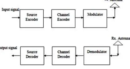
Wireless communication is the fastest growing segment of communication industry, the most common form of wireless communication is radio. A general wireless communication system need to transmit and receive signal to and from long distances over various frequencies known as channels, these signals need to be coded and compressed for secure and faster communication with the ability to be able to reconstruct them accurately after passing through the channel which introduces noise in them. Thus, the general blocks needed for a communication system are as shown in figure 1.1
Figure 1.1: A General wireless Transmitter and receiver system
Research Development Cell, Government College of Engineering, Jalagon (M. S), India
Modulators [3]:
In telecommunications, modulation is the process of conveying a data signal, inside another signal, which is then physically transmitted. Modulator is the device, which modulates the characteristics of a high frequency carrier wave as per the input data signal. Modulators work on the principle of different modulation schemes which are mainly divided into 2 streams, they are:
1. Digital Modulation 2. Analog modulation
1. Digital Modulation:
Digital Modulation is a technique where an analog carrier signal is modulated by a discrete signal. Digital modulation methods can be considered as digital-to-analog conversion, and the corresponding demodulation. It is further categorized in different schemes based on what parameters the characteristic of the carrier wave is modulated.
a. Phase Shift Keying. b. Amplitude Shift Keying. c. Frequency Shift Keying.
g. Quadrature Amplitude Modulation.
h. Orthogonal Frequency Division Multiplexing (OFDM).
2. Analog Modulation:
Analog modulation transfers an analog data signal over an analog bandpass channel at a different frequency. Analog modulation schemes aim at transferring a narrowband analog signal over an analog baseband channel as a two-level signal by modulating a pulse wave.
a. Amplitude modulation. b. Phase modulation. c. Frequency modulation. d. Double sideband modulation. e. Single sideband modulation
Software Defined Radio (SDR):
Software defined radios are alternative form of radio systems. In hardware-defined radios, typical components such as mixers, filters, modulators, etc., are implemented in hardware, thus, hardware defined radios cannot be reconfigured in runtime by the user to switch to different vacant channels as per requirement. To satisfy this need of cognitive system software defined radios are used where we can configure the components in runtime as per the need and available channel [4]. In software, defined radios the components are implemented on FPGA boards, ASIC boards, or other general-purpose boards as per the application. The fundamental characteristics of SDR are that the software defines the transmitted waveform and the demodulated received signal. This offers a great flexibility for wireless communication. A variety of tools, algorithms and protocols can be implemented and verified easily in the same manner as if they were done in a testbed constructed by real radio platforms [5] [6].
GNU Radio:
Research Development Cell, Government College of Engineering, Jalagon (M. S), India
GNU Radio offers various functions such as Mathematical Operations, logical Operations, FFT/IFFT Blocks, Filters, etc. It also offers Type Conversion such as Float to Short block, Integer to float block and complex to real block. Different Sources and sinks are also offered which thus makes it easy to build any system. GNU component blocks are designed using C++ and connected using python [4] [7].
An example of such abstracted Flow graph is shown in figure 1.2, which shows data flow in between various blocks.
Figure 1.2 Data Flow Graph for GNU Radio [4].
USRP:
The universal software radio peripheral is the most common hardware used with the GNU Radio to build a SDR system. It consists of two main sub devices, a mother board and a daughter boards which can convey and/or receive data at different frequencies. The daughter boards can be easily exchanged which provides more flexibility to the system. The mother board consists of FPGA and their main function is to convert analog signals into baseband digital signal and vice versa thus needing ADC and DAC. To solve the issue of data realisation by ADCs and DACs at very high speed the daughter boards are introduced in the USRP
II. DESIGN OF AMPLITUDE MODULATOR
In amplitude modulation, the amplitude (signal strength) of the carrier wave is varied in proportion to the waveform being transmitted. That waveform may, for instance, correspond to the sounds to be reproduced by a loudspeaker, or the light intensity of television pixels. Implementation of Amplitude Modulation is shown in figure 2.1. The data flow graph has been designed by considering the following equations.
The carrier wave of frequency fc and amplitude A is given by: c(t) = A × sin(2πfct)
where, fc= 10 kHz and A=1.
The modulation waveform of frequency fm and amplitude M is given by: m(t) = M × cos(2πfmt)
where, fm=1 kHz and M= 0.7.
The amplitude-modulated wave is obtained by considering the following equation:
Research Development Cell, Government College of Engineering, Jalagon (M. S), India
Figure 2.1 Data Flow Representation of Amplitude Modulator
The output waveform for the above data flow graph of the Amplitude Modulator with the given specifications is shown in the figure 5.1
III.DESIGN OF SINGLE-SIDEBAND MODULATOR
Single-sideband modulation (SSB) is a improvement over amplitude modulation which uses transmitter power and bandwidth more efficiently. Amplitude modulation produces an output signal that has twice the bandwidth of the original baseband signal. Single-sideband modulation avoids this bandwidth doubling, and the power wasted on a carrier, at the cost of increased device complexity and more difficult tuning at the receiver. The data flow graph of the SSB modulator are designed using the following equations
SLSB (t) = s(t) × cos(2πfct) + ŝ(t) × sin(2πfct) .... For Lower side band SUSB (t) = s(t) × cos(2πfct) - ŝ(t) × sin(2πfct) .... For Upper side band
Where s(t) is the information signal, ŝ(t) is the Hilbert transform of the data signal and fc is the carrier frequency s(t) = cos(2πfmt)
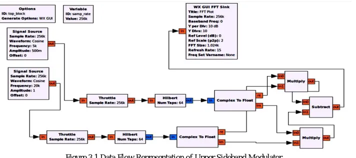
For upper side band modulator the data flow graph is as shown in the figure 3.1 and the output wave form in frequency domain is shown in the figure 5.2
Research Development Cell, Government College of Engineering, Jalagon (M. S), India
Figure 3.2 Data Flow Graph Representation of Lower Sideband Modulator
IV.DEMODULATION OF USRP GENERATED “.DAT”FILE
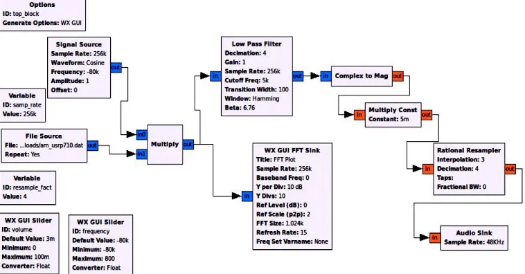
A data file is a file that contains several seconds of recorded signals from the AM broadcast band. This data file is obtained from a USRP. The .DAT file used contains a set of two recorded data of audio files at two different frequency bands. The amplitude-modulated signal from the .DAT file is demodulated using amplitude demodulation technique. Two sliders are used in the design, one to adjust the volume of the audio files and the other to slide to different frequencies to listen to both the audio files stored at different frequencies.
The design flow graph of the design is as shown in figure 4.1 and the output waveforms are as shown in figure 5.4 and figure 5.5
Research Development Cell, Government College of Engineering, Jalagon (M. S), India
V. EXPERIMENTAL RESULTS
The output waveform obtained for Amplitude Modulator using GNU Radio for the given specification is as shown in the figure 5.1:
Figure 5.1 Output waveform of Amplitude Modulator using GNU Radio
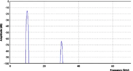
The output waveform obtained for Upper Sideband Modulator using GNU Radio for the given specification is as shown in the figure 5.2:
Figure 5.2 Output waveform of for Upper Sideband Modulator using GNU Radio in Frequency Domain
The output waveform obtained for Lower Sideband Modulator using GNU Radio for the given specification is as shown in the figure 5.3:
Research Development Cell, Government College of Engineering, Jalagon (M. S), India
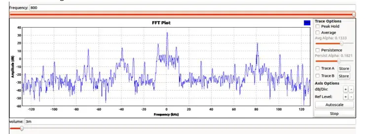
Figure 5.4 Demodulation of USRP generated .DAT file using GNU Radio for the audio file at 710 kHz
The output waveform obtained for Demodulation of USRP generated .DAT file using GNU Radio for the audio file at 790 kHz is as shown in the figure 5.5:
Figure 5.5 Demodulation of USRP generated .DAT file using GNU Radio for the audio file at 790 kHz
VI. CONCLUSION
In this paper, Amplitude Modulator, Single Sideband Modulator and demodulation of USRP generated .DAT file are studied and successfully implemented with the help of predefined general signal processing blocks present in GNU Radio software. It has been observed that GNU Radio provides high flexibility and ease in designing signal processing blocks with it’s main feature that allows to process real time data with high sampling rate and fast computation over other signal processing softwares. All of the above modulator and demodulation designs will help in understanding and improving the performance parameters of SDR The further scope of this paper is designing signal processing systems with the help of user constructed block generated by python and C++ coding.
REFERENCES
[1] J. Mitola III and G.Q. Maguire, Jr., “Cognitive Radio: Making Software Radios More Personal”, IEEE Personal Communication, Vol. 6, No. 4, Aug. 1999, pp.13–18.
[2] Niladri Shekhar Paria, booklet on cognitive-radio by wipro Ltd., IND/PMCS/WIPRO/DEC2015-FEB2016 [3] Rappaport, T.S., Wireless Communication: Principles and Practice, Second Edition Pearson Education, 2005. [4] DucToan Nguyen, “Thesis of Implementation of OFDM using GNU and USRP ” University of Wollongong,2013. [5] Guided tutorial on GNUradio. Available: http://gnuradio.org/redmine/projects/gnuradio/wiki/TutorialsCoreConcepts. [6] GNU Radio Companian, Available : http://gnuradio.org/redmine/projects/gnuradio/wiki/GNURadioCompanion.
[7] D. C. Tucker and G. A. Tagliarini, "Prototyping with GNU Radio and the USRP - where to begin", Proc. IEEE Southeastcon, Atlanta, GA, pp.50-54, Mar. 2009
[8] Shweta M,. Tayade and Dr. Vinay Chavan, “Challenges in Flexible Workflow Architecture: A Review”. Fourth International Conference on Emerging Trends in Engineering & Technology, 2011.
[9] Rajesh Bhambare, Rajeshree Raut, A Survey on Digital Modulation Techniques for Software Defined Radio Applications, International Journal of Computer Networks and Wireless Communications (IJCNWC), ISSN: 2250-3501 Vol.3, No3, June 2013 .
![Figure 1.2 Data Flow Graph for GNU Radio [4].](https://thumb-us.123doks.com/thumbv2/123dok_us/1513606.1185425/3.595.136.459.256.413/figure-data-flow-graph-for-gnu-radio.webp)