18th International Conference on Structural Mechanics in Reactor Technology (SMiRT 18) Beijing, China, August 7-12, 2005 SMiRT18-S07-3
A STUDY ON THE EFFECT OF THERMAL CAPACITY TO REACTOR
CONTROL
Song SoonJa
Korea Atomic Energy Research Institute, P.O.Box 105,Yuseong,Daejeon,
305-600,Korea Phone: +82-42-868-8375 E-mail: [email protected]
Park WonSeok
Korea Atomic Energy Research Institute, P.O.Box 105,Yuseong,Daejeon,
305-600,Korea Phone: +82-42-868-8375 E-mail: [email protected]
ABSTRACT
The safety features of a high temperature gas-cooled reactor are their inherent safety features because the structures of reactor are equipped with graphite material having a thermal resistance and a large heat capacity. This is an advantage to safely keep the reactor safety but it is assumed to affect the response of the power control. The thermal capacity was investigated and analyzed to increase the performance of reactor.
Keywords:thermal capacity, response, high temperature gas-cooled reactor
1. INTRODUCTION
In order to reach high temperature around 700~1600°C, the high temperature gas-cooled reactor (HTGR) is generally equipped with a mount of graphite material in the reactor. The characteristics of graphite material are a high moderation rate of the neutron, a thermal resistance and a large heat capacity. In these reasons, Graphite material has been equipped at the upper, bottom and side graphite reflectors surround the reactor core. Graphite is also used to be coated with fuel particles[1].
The advantages of high temperature reactors having a mount of graphite structure are their inherent safety features. The safety features include the passive decay heat removal and reactor self-shutdown under accident conditions through a negative reactivity temperature coefficient. However, the advantages for thermal resistance and inherent safety features are affected to delay the response of reactor when the rated-power changes. Studying the effect of thermal capacity is necessary to increase the reactor performances for continuous power operation of pebble bed reactor.
The structure of high temperature reactor with graphite material has the big differences from the pressurized water reactor and the fast breeder reactor. In this paper, the effect of thermal capacity on the structure of HTGR will be investigated and compared with the pool type reactor having the large thermal capacity to find delay effect and reduce control problems. The transient system analysis code called with CAHTR(control analysis for HTR) is used to investigate the differences.
2. STRUCTURE OF THE REACTOR
In HTR-10, helium is used as the coolant and its nuclear core where heat is generated from the nuclear fuel is in the form of a pebble bed. HTR-10 consists of a reactor core, a steam generator, a hot gas duct, a helium blower.
The helium gas heated at the core region exits the core region by the path located at the bottom of the core region and flows to the SG (Steam Generator) through the piping which connects the reactor block and the steam generator block as shown in Fig.1. In the steam generator, hot helium gas flows into the big cavity in the steam vessel and then changes its flow direction and flows to the top of the cavity, and again changes its flow direction and flows to the heat exchanger outside the cavity to exchange the heat to the secondary SG fluid. After the heat exchange, the helium gas flows to the helium blower located at the top of the steam vessel, and then exits the SG after changing its flow direction again. The helium exited from the SG flows to the reactor block via piping and the helium which enters the reactor block flows though the graphite structure region to cool the structure and then enters the core region, and there it completes its circulation.
The reactor block is surrounded by a building structure. The external surface of the reactor vessel is cooled by air convection. Further detailed information on HTR-10 can be found in the references [1~6]. For the core power control, temperature sensors for measuring the hot temperature of the helium are located at the inlet of the steam generator [6].
A
M-M HPC
Fuel handling System He Blower
Reflector
Heat Exchanger
Core
S/G System Reactor
Fig. 1 Structure of the reference system, HTR-10
3. THERMAL CAPACITY OF THE REACTOR STRUCTURE
The comparison of thermal capacity effects of a system can be approximately made using the factor K which is defined by the following equation.
c v
Q dt T MC
K= ∆ / where,
MCv: product of the system mass and specific heat dT/dt: typical system temperature change rate Qc: rated core power
liquid metal reactor is 0.3. It means the thermal capacity effects of the reference design are relatively very large. The test results, however, show that control is well made at various power operation modes.
It seems the good controllability comes from the short system circulation time, which is the required time for the coolant to make its one full circulation. The circulation time has the meaning how fast control information is propagated throughout the system. The time for HTR-10 is about 20 seconds while that of KALIMER-150 is about 180 seconds. Though the K value of the reference design is seven times larger than KALIMER, its circulation time is on ninth of KALIMER and the short circulation time compensates the large thermal damping by its fast control information propagation.
As explained above, the large thermal capacity of a system structure generally degrades the control performance and these effects were investigated by changing the thermal capacity of the reactor structure though the parameters Ccapa that adjust the specific heat of the reactor and insulator material respectively.
The parameter Ccapa was increased and its effects were observed. When the core power was controlled by the
temperature at the core exit, the control was still good even though Ccapa was increased to 5 and no significant
deviation of the controlled parameter value from the its target value was observed.
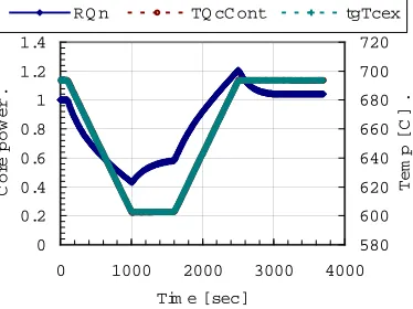
When the temperature at the SG inlet was used, however, the overshooting in the core exit temperature became very serious and the temperature reached at 864C when Ccapa was 5. Figure 2 is for the results with Ccapa =2 and it
shows the core power overshoots to 120% and the core exit temperature to 783C which is a about 90C overshoot. This overshoot is serious and can results in a severe thermo-mechanical load on the structure.
(6 -2)
0 0.2 0.4 0.6 0.8 1 1.2 1.4
0 1000 2000 3000 4000
Tim e [sec]
Co
re
pow
e
r
.
580 600 620 640 660 680 700 720
Te
m
p
[C
]
.
RQ n TQ cC ont tgTcex
200 300 400 500 600 700 800
0 1000 2000 3000 4000
Tim e [sec]
Te
m
p
[C
]
.
TfRxin TfC in TfC ex TfSG in
a. Core power and temperature parameters b. Comparison of the temperatures
Fig. 2 Control at Ccapa =2
When the factor Ccapa was decreased to 0.5, the overshoot became very small as expected. From this, it can be said
that temperature measurement location for the core power control can be very important coupled with a system thermal capacity.
Also the large capacity effects can be found in the feed water control. The steam temperature rises from the transient helium temperature (TqcCont) that is kept much higher than the steady state temperature (tgTCex) corresponding to the transient power because of the large capacity of the reactor structure. Since the helium temperature is higher than its corresponding steady state value, the heat transfer rate in the SG becomes larger than that from the steady state condition which was the basis of the target feed water flow rate and the steam temperature becomes increased though the core power decreases.
4. HEAT TRANSFER COEFFICIENT
the combination of the coefficient value with other relevant system parameter values, the system may become very difficult to control or uncontrollable in a worst case as will be shown later in this section.
The heat transfer coefficient effects were investigated by changing the values for the core region with the adjustment parameter CuaCore. The parameter CuaCore was increased from 1.0 and its effect was calculated by CATHR for the controls with different locations of the hot helium temperature. The control with the temperature at the core exit, the controllability was maintained even CuaCore was increased to 10 as shown in Fig. 3. Only an overshoot of 5% was observed in the core power and other system parameters were well controlled.
0 0.2 0.4 0.6 0.8 1 1.2
0 1000 2000 3000 4000
Tim e [sec]
Co
re
pow
e
r
.
600 620 640 660 680 700 720
Te
m
p
[C
]
.
RQ n TQ cC ont tgTcex
Fig. 3 Control at CuaCore =10 with Core Exit Sensing
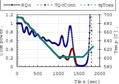
When the control was made by the SG inlet temperature, the control became unstable and the power overshoot appeared even at CuaCore was 1.4. The overshoot was more serious than the case of Fig. 3 and its peak value was 12% with rapid oscillation. As CuaCore was increased further to 1.5, the system control failed as shown in Fig. 4.
0 0.2 0.4 0.6 0.8 1 1.2
0 500 1000 1500 2000
Tim e [sec]
Co
re
pow
e
r
.
580 600 620 640 660 680 700
Te
m
p
[C
]
.
RQ n TQ cC ont tgTcex
Fig.4 Control at CuaCore =1.5 with SG Exit Sensing
Investigation on the control response showed that the temperature error for the control was too much compensated and it was tried to cure the control failure of Fig.4 by decreasing the magnitude of the temperature by a constant Ccontp which is similar to the constant in a proportional control algorithm. The introduction of Ccontp adjusted the
control failure somewhat but there were serious oscillation as shown in Fig. 5.
Comparison of the figures in Fig.5 shows that decreasing the factor Ccontp will not solve the situation since there is
0 0.2 0.4 0.6 0.8 1 1.2 1.4
0 1000 2000 3000 4000
Tim e [sec]
Co
re
pow
er
.
580 620 660 700
Tem
p
[C
]
.
RQ n TQ cC ont tgTcex
0 0.2 0.4 0.6 0.8 1 1.2 1.4
0 1000 2000 3000 4000
Tim e [sec]
Co
re
po
w
e
r
580 600 620 640 660 680 700 720
Te
m
p
[C
]
.
RQ n TQ cC ont tgTcex
a. Control with Ccontp =0.2 b. Control with Ccontp=0.05
Fig.5 Control with Ccontp for the case of Fig.4
This result shows that measuring temperature for the hot temperature of the coolant for control away from the core exit can cause a serious difficulty at the system control depending on the structural heat capacity and the heat transfer coefficient values. It is highly desirable to consider the controllability at the system design when the measurement needs to be made away from the core exit from some reasons such as structural limitations.
5. CONCLUSIONS
The thermal effects were investigated with the HTR-10 as the reference system design and the major conclusions are as follows. The basic controllability of the HTR-10 is very good even though it has large thermal capacity because the short time of the flow circulation compensates the large thermal damping by its fast control information propagation. However, the controllability is affected on the different measurement location so that it should consider the system dependency to design a reactor system. In addition to these results, it is needed to research the graphite particles to affect the power control.
ACKNOWLEDGMENT
This work has been carried out under Nuclear Hydrogen Production Technology Development and Demonstration (NHDD) Project which is supported by MOST (Ministry of Science and Technology).
REFERENCES
1. Zongxin Wu and Dengcai Lin, “The design features of the HTR-10”, NED, 218, 2002
2. He Shuyan et al, “The primary confinement and pressure boundary system of the HTR-10”, NED, 218, 2002 3. Zhang Z.S. et al “Structural design of ceramic internals of HTR-10”, NED, 218, 2002
4. Zuying Gao and Lei Shi, “Thermal hydraulic calculation of the HTR-10 for the initial and equilibrium core”, NED, 218, 2002
5. Huang Z.Y. et al, “Design and experiment of hot gas duct for the HTR-10”, NED, 218, 2002 6. Zhong S.P. et al, “Thermal hydraulic instrumentation system of the HTR-10”, NED, 218, 2002 7. EPRI, ALWR URD, Vol.2, Chap.1, Sect. 3.4, USA, 1990