IMPLEMENTING SHORTEST
PATH CALCULATION FOR 3D
NAVIGATION SYSTEM
Muhamad Uznir Ujang
Alias Abdul Rahman
Department of Geoinformatics,
Faculty of Geoinformation Science and Engineering,
Universiti Teknologi Malaysia, 81310 UTM Skudai, Johor, Malaysia.
ABSTRACT
1.0 INTRODUCTION
There are a number of disaster based or emergency applications especially within high rise building in urban areas best be served by shortest path routine. A system that could provide a route network within a building helps to locate safety routes for example to people in fire and rescue missions and other emergency operations. Other navigation applications in this domain like pedestrian navigation, and even for car navigation on roads or in racing circuit using computer game engine is also worth to mention. Balstrom (2001) listed some of the applications that need this kind of routine e.g. searching the nearest restaurant, a petrol station, jungle trekking on the mountain/hills, locating the emergency exit doors during fire (emergency) in a building (Meijers et al., 2005). It has been recognized that Dijsktra’s algorithm could be used for this sort of applications that is by extending to three-dimensional (3D) environment. Shortest path network for multilevel buildings thus the connectivity between levels or floors are certainly be very useful and interesting to be investigated. Several works have been done on Dijsktra’s algorithm for 3D environment such as Karas et al. (2006). Other related work such as Meijers et al. (2005) and Pu and Zlatanova (2005) focused on indoor navigation routing. However, it is interesting to note that works on inexpensive 3D game engine is getting ground compares to fully operational commercial game engine like Quake. Fritsch (2003) investigated the Quake game engine for his indoor navigation system. In this chapter the focuses is on having 3D shortest route together with inexpensive game engine for our navigation system.
system with respect the development of whole new idea of navigation for 3D GIS are highlighted in Section 5.
2.0 3D GAME ENGINE
2.1 The Basic
Today, many game engines are avialable in the market and the cost varies. 3DState game engine is inexpensive and downloadable from the Internet (www.3dstate.com). Most of game packages consist of game engine, individual game rules and game data includingn geometry and texture (Fritch, 2003 and Beck, 2002) as illustrated in Figure 3.
Figure 3: Components of a 3D computer game (adapted from Beck, 2002)
The available components in the game allow us to navigate within the scene and in this case the indoor navigation of building elements. A game engine is some sort of machine to visualize 3D worlds in real time using basic elements of a game which are not to be programmed over and over again. Today, a game engine is a very complex software system containing many elements and which is also capable of distributed processing (Fritsch, 2003).
2.2 The 3D State Engine
that if the engine’s new versions are released, users will only have to replace the previous version with the new version instead of changing their codes. Moreover, users do not even have to recompile their codes again. From the literature, we can see that most of the new type of GIS such as 3D GIS and web-based GIS are moving towards a system with 3D visualization as an end component.
3.0 THE DIJKSTRA’S ALGORITHM
Figure 1: Several connected nodes.
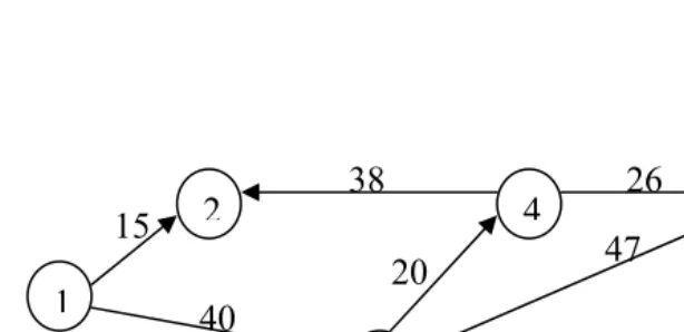
For the network on Figure 1, let us assume that we want to go from node #1 to node #6, here node #1 is the source node, and the destination is node #6. The algorithm considers all the nodes known as unlabeled nodes. Firstly, the calculation begins with node #1 (source node) and this node automatically be labeled as permanent and could be noted as [0, -]. The distance value is 0 and there is no value for the predecessor node label because it does not yet move from the source node location. Then after node #1 has been labeled as permanent, then it will look for the successor of node #1. In this case, the successor is node #2 and node #3. Then it will choose node with the shortest distance (d) between node #1 and with its successor nodes. The distance (d) is being calculated by adding the d value for node #1 label with the distance between node #1 and node #2 or node #3. For node #2, the distance is 0 + 15 = 15 and for node #3 its d = 0 + 40. Thus, in this case the shortest distance between node #1 with it successor is node #2 (i.e. d = 15). Node #2 will be labeled as permanent [15, 1] and node #3 will be labeled as temporary. Thus at this stage, the unlabeled nodes are #4, #5, #6, and #7.
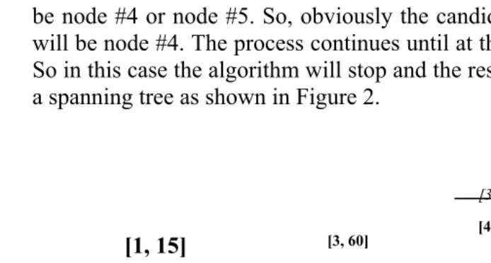
The next step is to get the last permanent node (i.e. node #2). Here, the same procedure will be applied, i.e. to check the potential node candidate. In this case, there is no node after nodes #2 – because of the opposite direction. The candidate (i.e. pointer) at node #1 looks for alternative route i.e. node #3 (with d = 40). When the pointer is at node #3 then it will look for the shortest route and in this case it could be node #4 or node #5. So, obviously the candidate for the next node will be node #4. The process continues until at the end of the network. So in this case the algorithm will stop and the result for this network is a spanning tree as shown in Figure 2.
*Italic labeling indicates a temporary label *Bold labeling indicates a permanent label
Figure 2: Spanning tree. 2 3 4 5 1 7 6 [1, 40] [1, 40] 15 40 26 25 18 20 [0, -]
[1, 15] [3, 60]
[3, 87]
[5, 111] [4, 86]
[5, 131]
Figure 2 shows the entire route (from node 1 to the other nodes). Thus, the loop for the network is node #1 > node #3 > node #4 > node #5 > node #7 > node #6.
4.0 THE EXPERIMENT AND NAVIGATION INTERFACE DEVELOPMENT
4.1 3D Network
In order utilize Dijkstra’s algorithm for 3D environment, first we need to establish a 3D network for the environment, like 3D building. Important information like IDs, distances, and potential candidates of nodes in the network are fundamental in this problem domain. Normally, all these information are available in the 3D network and we have to extract and assign them with proper node IDs. By putting ID to each node then the network is now applicable to Dijkstra’s algorithm.
The distance in 3D network between nodes could be easily calculated. Other important information like coordinates (x, y, z), IDs, predecessor and node’s successor are already availabe in the network.
4.2 Study Area
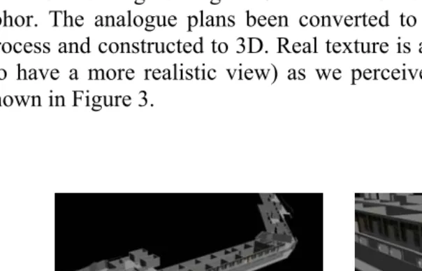
Study area for the experiments is building of Faculty Geoinformation Science and Engineering at Universiti Teknologi Malaysia, Skudai, Johor. The analogue plans been converted to digital via digitization process and constructed to 3D. Real texture is attached to the building (to have a more realistic view) as we perceived in the real world as shown in Figure 3.
Any generated building models must be in a useable format, i.e. format supported by the 3D engine (3DState Engine). The engine supports several types of 3D environment format such as (*.wld, *.morfit, *.3dstate, *.STATE). Various converters are freely available in the Internet to convert from another 3D model formats. The 3DState package also includes several 3D converters.
4.3 The Development Process
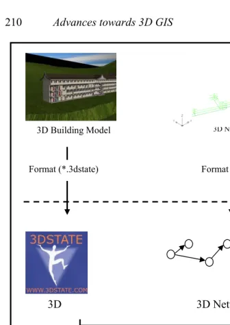
The general development process is illustrated in Figure 4. The Spatial Data (3D Building Model and 3D Network) phase was developed for data input. The Game Development phase as indicated in the figure explains the main processing stage in the development. The end output as in the form of system interface works and could be demonstrated live as an operational navigation system.
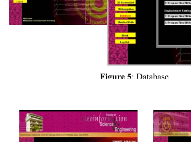
Figure 5 shows the database initialization by selecting the 3D network data file and also the 3D environment file. On the other hand, Figure 6 shows the system interface for user to select their current location and destination locations (based on Room’s ID or Staff Name) prior to begin the Dijkstra’s shortest route calculation. The user can also acquire the required information by selecting the Building blocks, Floors, Room’s ID and Room’s Name of the building by using the Advance Search windows (see Figure 7). These windows can be useful for unfamiliar users of the building and have no prior knowledge of the building as poses by rescue operation personnel.
Path Calculation Result windows for the 3D network based on the user current location and destination location.
Figure 4: 3D navigation development process
3D 3D Network
Format (*.3dstate) Format (*.MW)
SPATIAL DATA
GAME DEVELOPEMENT
RESULT
3D Building Model 3D Network
Figure 5: Database
Figure 6: Shortest path windows
User of this navigation system also able to control the way he or she would like to navigate. Users can move from one point to another in theFKSG 3D building environment without having a prior knowledge about the building and they are also able to see the real textures of the 3D building. In terms of realistic movements, implementation is made by simulating human movement so that users can navigate as like they were walking inside of the building (see Figure 9).
5.0 CONCLUDING REMARKS AND FURTHER WORK
Dijkstra’s algorithm implementation for 3D navigation by incorporating inexpensive 3D game engine capable of providing shortest route information in 3D environment. It is operational navigation software and could be extended for much larger 3D world. The approach works and certainly is useful for any agencies and personnel who deal with stress or non-stress operations like building emergency rescue and missions, and evacuations. Other applications like exploration and development planning, gas utilization, pipelines
and piping design, facilities and drilling operations as well as for health and safety would benefit from this research outcome.
Our future work is to extend the approach utilizing more stable 3D game engine, incorporate with more realistic navigation tool and also to be able to manipulate 3D objects for indoor and outdoor 3D navigation system.
REFERENCES
3D State Game Engine (www.3dstate.com)
Balstrom, T. (2001). Identifying Least Cost Routes in Mountainous Terrain.
http://gis.esri.com/library/userconf/proc00/professional/papers Beck, M. (2002). Realisierung eines Geoinformationssystems –
Visualisierung und Analysefunctionalalitat mit einur 3D Engine. Master thesis, Stuttgart University, Institute for Photogrammetry (ifp), Germany.
Fritsch, D. (2003). 3D building visualization – Outdoor and indoor applications. Photogrammetric Week Proceedings, Stuttgart, Germany.
Karas, I.R., F. Batuk, A. E., Akay, and I. Baz (2006). Automatically extracting 3D models and network analysis for indoors. In. Innovations in 3D Geo Information Systems, Springer-Verlag, Heidelberg, pp. 395-404
Meijers, M., S. Zlatanova and N. Pfeifer (2005). 3D Geo-Information Indoors: Structuring For Evacuation. Delft University of
Technology, the Netherlands.