ANALYSIS OF CYLINDRICAL SHELLS BASED ON FOUR SHELL
THEORIES BY SEGMENTATION METHOD
P.Desai1, T. Kant2 1
Manager (Design), S N Bhobe and Associates Pvt. Ltd., Navi Mumbai – 400 705 2
Institute Chair Professor, Department of Civil Engineering, Indian Institite of Technology Bombay, Powai, Mumbai 400 076
E-mail of corresponding author:[email protected], [email protected]
ABSTRACT
A class of shell theories, which are derived from the three-dimensional elasticity equations by expanding the displacement vector in Taylor’s series in the thickness coordinate, is first reviewed. A theory for general shell deformation is then developed based on a higher-order kinematic model for layered shells. The theory accounts for the effects of transverse shear deformation, transverse normal stress and transverse normal strain with an implicit nonlinear distribution of the tangential displacement component through the shell thickness. The theory is shown to result in a partial differential equation system of sixteenth order. The scope of the segmentation method is extended to the solution of composite layered cylindrical shells; cantilever and diaphragm supported boundary conditions. Governing first-order ordinary differential equations are derived for each of four theories, classical Love shell, Reissner-Nagdhi, and a higher-order shear deformation theory of 9 and 12 degrees of freedom. Reissner’s mixed variational theorem is used to derive the equilibrium equations.
INTRODUCTION
Structural shell forms-a body bounded by two curved surfaces, are extremely important structural elements in applications such as nuclear reactors, pressure vessels, spacecrafts, missiles, etc. The development of the theoretical model (the theory) to describe its behaviour is an area of continuing interest. The so-called ’thin shell theory’, originally formulated by Love in 1888, is firmly established by Love, [1, 2]. It is used extensively for analytical solutions and numerical analysis and further is continuously being applied to new problems to generate much needed design data. However, its use in many practical applications involving complex geometries and loadings, cut-outs, branches, intersections, contact problem involving shells, laminated shells, etc. is not at all effective because of the implicit simplistic assumptions in the theory. This calls for the development of more refined and higher-order shell theories.
Here, we are concerned with the derivation of a particular higher-order general shell theory. The behaviour of the shell, in any theory is governed by the behavior of an appropriate reference surface. This necessitates the transformation of the three dimensional (3D) elasticity equations into an approximate system of two dimensional (2D) shell equations. This transformation is an essential feature of any plate or shell theory. The situation is further complicated by the coupled nature of the membrane and bending behaviour especially in shells. These coupled deformations, in the form of stretching and curvature change of the reference surface, are required in predicting the strains that exist throughout the shell space.
In the present work, Governing equations are derived for a multilayered cylindrical shell subjected to symmetric loading using a higher order displacement Model. The manipulation of the governing equations into an equivalent system of first order ordinary differential equations is shown. Numerical results are presented for a cylindrical shell subjected to symmetric loading and different boundary conditions. Both single layered and multilayered cylindrical shells are analyzed. Numerical analysis of governing differential equations is done using segmentation method. Two computer programmes for segmentation method are developed in FORTRAN-77.
SHELL THEORY FORMULATION
1 1 1
2 2 2
3 3
U u z
U u z
U u
θ θ
= +
= +
=
(4)
Where z is the co-ordinate normal to the reference surface, and u ,u , and 1 2 θ1 θ2 and u3 have dependence upon the
curvilinear co-ordinates α1 and α2which describe the reference surface. Hildebrand, Reissner and Thomas [3]
proposed a higher-order theory by dispensing with all the Love’s assumptions. The term higher-order, as used herein, refers to the level of truncation of terms in the Taylor series expansion for displacements. They used displacement forms of the type:
(
)
2
i i i i
U =u +zθ +z u , i=1,2, & 3∗ (5)
They however, concluded, based on their simplistic analysis that the third terms in the tangential surface displacement components in relations (5) did not lead to improved results. It was this result, which perhaps prompted Naghdi [4] to develop a complete shell formulation based on the displacement forms:
1 1 1
2 2 2
2
3 3 3 3
U u z
U u z
U u z z u
θ θ
θ ∗
= +
= +
= + +
(6)
Kant and Ramesh [6] presented a general orthotropic shell theory based on the displacement forms (5) and using a variational principle of displacements. Kant [7] extended this work for laminated orthotropic/composite shells where thermal strains are also considered.
In the present work, the displacement expansions for a general shell are written concisely as,
2 3
1 1 1 1 1
2 3
2 2 2 2 2
2 3
3 3 3 3 3
1
1
2
6
1
1
2
6
1
1
2
6
' '' '''
' '' '''
' '' '''
U
u
zu
z u
z u
U
u
zu
z u
z u
U
u
zu
z u
z u
=
+
+
+
=
+
+
+
=
+
+
+
(7)
Fourth term in the displacement field is introduced for the improvement of bending behavior of the shell. The general shell equations, so derived, [8] are particularized for an axisymmetric shell, more specifically for a cylinder,
for which the longitudinal (U1) and the transverse (U3) displacement components define the displacement field and
Eq. (7) reduces to,
2 3
1 1 1 1 1
2 3
3 3 3 3 3
1
1
2
6
1
1
2
6
' '' '''
' '' '''
U
u
zu
z u
z u
U
u
zu
z u
z u
=
+
+
+
=
+
+
+
(8)
The boundary-value problem is formulated in terms of 16 differential equations called the ’intrinsic equations’ involving only 16 unknowns - called the ’intrinsic dependent variables’. The other variables are related to the intrinsic variables by algebraic relations. One of the two coordinates describing the problem is selected as a preferred coordinate in the basic method of analysis. In the present case, due to symmetric loads, the problem is described in terms of φ - the meridional coordinate only and therefore the choice of the preferred coordinate is a straight-forward one. Intrinsic equations are derived consisting of a system of 16 first-order ordinary differential equations with respect to φ, containing the 16 intrinsic variables which appear in the boundary conditions on the
edge φ = constant. For the present problem, y, defining the vector of intrinsic variables consists of,
(
' '' ''' ' '' ''')
1
, ,
1 1,
1, ,
3 3,
3,
3,
11,
11,
11,
11,
11,
11,
11,
11t
y
=
u u u u u u u u
N
M
P M
∗Q S T S
∗ (9)The governing equations are arranged in such a way that the derivatives of the intrinsic variables with respect to φ
(Axial coordinate) for a given value of φ are computed in a straight-forward manner, when the physical and
equations and the associated auxiliary relations are derived in a systematic manner for symmetrically loaded orthotropic/layered shells of revolution. These are numerically integrated by a specially developed procedure called the segmentation method [9].
EQUILIBRIUM EQUATIONS AND BOUNDARY CONDITIONS
For deriving the equilibrium equation, the principle of minimum potential energy is chosen due to its simplicity and also because its application gives simultaneously the natural boundary conditions that are to be used with the theory. The total potential, π for the shell element is defined as,
1 2
s e e
U
W
W
W
=
−
−
−
π
(10)Where U is strain energy of the elastic shell,
Ws is the contribution to the ‘load potential’ and equals the external work done by body and surface tractions, and
Wel and We2 are another contribution to the ‘load potential’ and equal the external work done by edge
forces. For π to be stationary
δπ = 0 (11) or
(
U W
−
s−
W
e1−
W
e2)
=
0
δ
(12)The expression for the variation of the strain energy is given by (Reissner [5])
1 1 2 2 3 3 12 12 13 13 23 23 1 2 1 2 1 2
1 2
(
)
(1
) (1
)
z
U
=
∫ ∫ ∫
+
+
+
+
+
A A
+
k z
+
k z d
d
dz
α α
δ
σ δε
σ δε
σ δε
τ δγ
τ δγ
τ δγ
α
α
(13)
Term-by-term evaluation of the above integral is carried out, by making use of the relations given by Eqns. (13). Under symmetric loading, τ12 = 0 and τ 23 = 0, Further, all shell variables are independent of θ. Making these simplifications, and the following eight equations are obtained:
NUMERICAL EXAMPLES
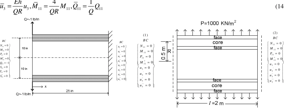
Example 1
The first example is that of a circular cylindrical shell subjected to a unit transverse shear at one edge and clamped, at the other edge (Fig. 1a). This particular example is chosen principally due to the fact that all the discrete values of the stress-resultants and displacements due to Kant (HOST6)[6] are available. For comparative study the geometrical and material properties are taken to be, length l = 25 inches, radius R = 10 inches, thickness h = 2.5 inches, Young’s modulus E = 30.0 × 10⁶psi, and Poisson’s ratio µ = 0.3, h/R = 1/4. For the sake of one-to-one, correspondence with the results to be compared, the shell length is divided into 50 segments; the length of individual segment is 0.5 inch. Each segment is then divided into 5 subdivisions for numerical integration with the Runge-Kutta-Gill algorithm. Results using the theoretical formulation and the numerical technique for solution described earlier are compared explicitly with those of Kant [9] and Baluch [11] at discrete points along the length (Table 1).
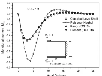
Important stress-resultants, such as M11,Q11, etc and the u3 displacement component are further plotted and
compared in Figs. 2-4 to see and verify the nature of variation for all four theories, Classical Love Shell[2], Reissner Naghdi [4], Kant(HOST6) [9], and Present (HOST8). The same example is also used for parametric study. For this
study, shell length l = 25 inches, radius R = 10 inches, and Young’s modulus E = 30 × 106 psi are taken to be fixed.
Thickness h is varied so as to obtain h/R ratio to be 1/50. Number of segments and number of subdivisions within each segment that are found suitable for the parametric study corresponding to a particular combination of h/R ratio, without giving any numerical instability problem are summarized below for any future reference.
For h/R = 1/5, No. of segments = 50, No. of subdivision within each Segments = 5 and for h/R = 1/50, No. of segments = 400, No. of subdivision within each segments = 5, Length of each segments for h/R=1/5 is 0.5 and for h/R=1/50 is 0.0625.
(a) From the comparative study done it is seen that all the stress-resultants M11, M22, N22 and Q11 and the transverse
[9] to establish the correctness of the theory. (b) From the parametric study made with reference to h/R, the
following points, some of which are obvious, are observed: (i) Maximum values of M11 and M22 increase with
increasing h due to increasing stiffnesses. (ii) Maximum value of N22 (N11 being zero because of one edge being free) increases with decreasing h due to increasing flexibility, making membrane action predominant. The same
holds good for u3 as well. (iii) The edge effect is seen to travel over a longer length with increasing h, is directly
proportional to h1/2. Following nondimensional parameters are used for this example.
3 3 11 11 11 11
4 1
, ,
Eh
u u M M Q Q
QR QR Q
= = = (14)
1 1 1 1 3 3 3 3 0 0 0 0 0 0 0 0 ' '' ''' ' '' ''' BC u u u u u u u u = = = = = = = = 11 11 11 11 11 11 11 11 0 0 0 0 1 0 0 0 * * BC N M P M Q S T S = = = = = − = = = 11 11 11 11 3 3 3 3 (1 ) 0 0 0 0 0 0 0 0 * ' '' ''' B C N M P M u u u u = = = = = = = = 11 1 1 1 1 1 1 3 3 3 3 (2) 0 0 0 0 0 0 0 0 * ' ' ' ' '' B C N M P M u u u u = = = = = = = =
Fig. 1a: Cantilever circular cylindrical shell subjected to unit shear at the free edge
Fig. 1b: Diaphragm supported sandwich (0o/core/0o)
cylindrical shell subjected to external pressure
0 5 10 15 20 25
-1 0 1 2 3 4 5 6 '' 25 11 1
Q = −
11 1
Q = −
6
30 10 , 0.3
E= × psiν=
h/R = 1/4
Axial Distance T ra n s v e rs e n o rm a l d is p la c e m e n t u3
Classical Love Shell Reissner-Naghdi Kant (HOST6) Present (HOST8)
0 5 10 15 20 25 -1.0 -0.9 -0.8 -0.7 -0.6 -0.5 -0.4 -0.3 -0.2 -0.1 0.0 0.1 0.2 '' 25 11 1
Q= −
11 1
Q= −
6
30 10 , 0.3
E= × psiν=
h/R = 1/4
M e ri d io n a l m o m e n t M 1 1 Axial Distance
Classical Love Shell Reissner-Naghdi Kant (HOST6) Present (HOST8)
0 5 10 15 20 25
-1.0 -0.8 -0.6 -0.4 -0.2 0.0 0.2 0.4 '' 25 11 1
Q= −
11 1
Q= −
6
30 10 , 0.3
E= × psiν=
h/R = 1/4
T ra n s v e rs e S h e a r Q1 1 Axial Distance
Classical Love Shell Reissner-Naghdi Kant (HOST6) Present (HOST8)
Fig. 3a Meridional moment in thick shell – Example 1
Fig. 3b Transverse shear in thick shell – Example 1
0 5 10 15 20 25 -5 0 5 10 15 20 '' 25 11 1 Q= −
11 1 Q= −
6 30 10 , 0.3 E= × psiν= h/R = 1/50
T ra n s ve rs e n o rm a l d is p la c e m e n t u3 Axial distance Classical Kant (HOST6) Present (HOST8)
0 5 10 15 20 25 -0.16 -0.14 -0.12 -0.10 -0.08 -0.06 -0.04 -0.02 0.00 0.02 '' 25 11 1 Q= −
11 1 Q= −
6 30 10 , 0.3 E= × psiν=
h/R = 1/50
Axial distance M e ri d io n a l m o m e n t M 1
1 Classical
Kant (HOST6) Present (HOST8)
0 5 10 15 20 25 -1.0 -0.8 -0.6 -0.4 -0.2 0.0 0.2 0.4 '' 25 11 1 Q= −
11 1 Q= −
6 30 10 , 0.3 E= × psiν=
h/R = 1/50
Axial distance T ra n sv e rs e S h e a r Q1 1 Classical Kant (HOST6) Present (HOST8)
Fig. 4a Transverse normal displacement in thin shell – Example 1
Fig. 4b Meridional moment in thin shell – Example 1
Fig. 4c Transverse shear in thin shell – Example 1
Table 1: Values of transverse normal displacement (
u
3) along length of circular cylindrical shell (Example – 1)Inches Classical Love Shell [2] Reissner – Naghdi [4,5] Kant HOST6 [9] Present HOST8 Baluch [11]
0 5.1413 5.3603 5.3640 5.3873 0.528375
1 3.8453 3.8295 3.8325 3.8438 0.380175
2 2.6768 2.5740 2.5763 2.5718 0.254550
3 1.7048 1.5750 1.5765 1.5653 0.155025
4 0.9495 0.8280 0.8295 0.8168 0.80850
5 0.4004 0.3057 0.3058 0.2961 0.29175
7 -0.1927 -0.2276 -0.2285 -0.2307 -0.4050
8 -0.3068 -0.3191 -0.3203 -0.3195 -0.31950
10 -0.3305 -0.3182 -0.3197 -0.3160 -3.1500
12 -0.2344 -0.2186 -0.2198 -0.2162 -0.21450
14 -0.1260 -0.1160 -0.1168 -0.1147 -0.11325
16 -0.0482 -0.0448 -0.0452 -0.0445 -0.04275
18 -0.0068 -0.0072 -0.0073 -0.0075 -0.00675
20 0.0072 0.0062 0.0062 0.0058 0.00675
21 0.0078 0.0072 0.0073 0.0070 0.00750
22 0.0061 0.0062 0.0062 0.0061 0.00675
23 0.0035 0.0040 0.0041 0.0040 0.00450
Example 2
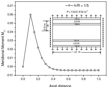
A diaphragm supported (0o/core/0o) two layered cylinder (Fig. 1b) is analyzed and compared with elasticity theory.
Subjected to external pressure of 1000 kg/cm2. The geometrical and material properties are R = 0.5 m and l = 2m.
Again, In view of symmetry about mid length, only half shell is analyzed. Following material properties [10] are taken for the (0o/core/0o) sandwich cylinder:
6 6 6 6
r
properties are
E 6.894 10 , E 172.36 10 , 6.894 10 , 1.378 10 ,
0.25, 0.25, 0.25
z zr
r zr z
Face Material
E G
θ
θ θ
ν ν ν
= × = × = × = ×
= = =
6 6 6 6
r
properties are
E 3.44 10 , E 0.275 10 , 0.275 10 , 0.413 10 ,
0.0199, 0.0199, 0.25
z zr
r zr z
Core Material
E G
θ
θ θ
ν ν ν
= × = × = × = ×
= = =
(15)
Number of segments and number of subdivisions within each segment that are found suitable for the numerical study are summarized below for any future reference. For h/R = 1/5, number of segments are taken as 400, number of subdivision within each segments as 5 and length of each segments are taken as 0.0025. Non-dimensional parameters are used for this example are same as follows.
3 2 3 11 11 11 11
4 4
, ,
o o o
Eh
u u M M Q Q
p R p Rh p Rh
= = = (16)
Fig. 5-6a-b shows the distribution of transverse normal displacement, meridional moment, and transverse shear in thick sandwich shell. Following points are observed from the results. (i) Maximum values of M11 and Q11 are directly proportional to h, because stiffness and hence the bending action increase with increase in h. (ii) Maximum
values of N11 increases with decrease in h due to increased flexibility. N22 attains the same maximum value away
from the clamped edge, the distance being more in the case of thicker shell due to increased edge disturbance. The
same holds good for u3 too. (iii) The edge effect is seen to travel more in the case of larger h confirming a known
fact.
Table 2 shows the comparison of numerical values obtained from the exact theory [12, 14] and from the present work for the isotropic case. Similarly, Table 3 shows the comparison of numerical values from the exact theory [13, 14]. From the comparison it is seen that the formulation derived in the present work is very accurate.
0.0 0.2 0.4 0.6 0.8 1.0
0.00 0.05 0.10 0.15 0.20
0
.5
m R
l =2 m P = 1 00 0 K N / m2
c o re fac e fac e
c ore f ac e
fac e
Axial distance
T
ra
n
s
v
e
rs
e
n
o
rm
a
l
d
is
p
la
c
e
m
e
n
t
u3
h/R = 1/5
0.0 0.2 0.4 0.6 0.8 1.0 -0.01
0.00 0.01 0.02 0.03 0.04 0.05 0.06 0.07
0
.5
m R
l =2 m P = 100 0 K N/ m2
c ore
f ac e f ac e
c ore
fa c e f ac e
Axial distance
M
e
ri
d
io
n
a
l
M
o
m
e
n
t
M1
1
h/R = 1/5
0.0 0.2 0.4 0.6 0.8 1.0
-0.04 -0.02 0.00 0.02 0.04 0.06 0.08 0.10 0.12 0.14 0.16
0
.5
m R
l =2 m P =1 0 0 0 K N/ m2
c o re
fa c e fa c e
c o re
fa c e fa c e
Axial distance
T
ra
n
s
v
e
rs
e
S
h
e
a
r
Q1
1
h/R = 1/5
Fig. 6a: Meridional moment in thick sandwich shell – Example 2
Fig. 6b: Transverse shear in thick sandwich shell – Example 2
Table 2: Comparison of radial displacements using various shell theories and elasticity theory for isotropic cylinder.
Table 3: Comparison of radial displacements using various shell theories and elasticity theory for orthotropic cylinder
l/R=4 l/R=20
h/R Ratios 1/5 1/50 1/5
No. of Segments 100 segments 400 segments 400 segments
Classical [1,2 ] 4.9880 50.0000 5.0000
Reissner – Naghdi (R- N) [4,5 ] 4.9880 50.0000 5.0000
HOST 6 [9] 4.9720 50.0000 4.9920
HOST 8 (Present) 4.9800 50.0000 4.9920
Semi Analytical [14 ] 5.2777 49.8475 5.3006
Timoshenko Plane Strain [12 ] 5.3028 50.3452 5.3028
l/R=4 l/R=20
h/R Ratios 1/5 1/50 1/5
No. of Segments 100 segments 400 segments 400 segments
Classical [ 1,2] 0.3240 3.2404 0.3240
Reissner – Naghdi (R- N) [4,5
] 0.3212 3.2597 0.3212
HOST 6 [9 ] 0.3279 3.2597 0.3279
HOST 8 (Present) 0.3275 3.2597*(800 Segments) 0.3275
Semi Analytical [14 ] 0.3435 3.2822 0.3438
CONCLUSION
A higher-order general shell theory is presented for thick circular cylindrical shells of finite length cantilever and diaphragm supported boundary conditions. The complete derivation is new. The formulation incorporates the effects transverse shear deformation with warping of the cross-section, transverse normal strain and transverse normal stress. The displacement model is consistent and represents refined modes of both bending and membrane deformations. Besides thick shells, this theory should find immense application for laminated shells where the distribution of the tangential displacement components through the thickness is nonlinear.
Nomenclature
z = Normal coordinate along the thickness direction
R
ɶ
= Position vector of a general point in shell spacer
ɶ= Position vector of a point on the reference surface
k1, k2 = Curvature of the lines of principal curvatures (along α1 and α2) dS1, dS2 = Differential areas of theedge faces
U
ɶ = Displacement vector of any point in the shell space having components U1, U2, U3 along α1, α2 and z directions
1 2 3
( , , )
i
u u u u = Linear displacements of a point of the reference surface along α1, α2 and z directions
' ' 1, 2
u u = Rotations of the normal to the reference surface in α1 and α2 directions
'' '' 1, 2
u u = Curvature terms along α1 and α2directions
' ''' 3, 3
u u = Account for the transverse normal stress and strain
1, 2 3
( , )
i
ε ε ε ε = normal strains
ij
γ
= Shearing strains1, 2, 3
σ σ σ = Normal stressess
12, 13, 23
τ τ τ = Shearing stressess
N11,M11 , etc. = Stress-resultants in α1or meridional direction N22,M22 , etc. = Stress-resultants in α2 or circumferential direction Q11, S11 , etc. = Transverse stress-resultants in z direction along α1 Q22, S22 , etc. = Transverse stress-resultants in z direction along α2
' '' '''
, , ,
i i i i
u u u u = Specified boundary displacement values
11 11,
N M etc. = Specified boundary stress resultant values
h = Thickness of a homogeneous isotropic/orthotropic shell
α1 or φ =Meridional coordinate of a shell of revolution
α2 or θ = Circumferential coordinate of a shell of revolution
, , , , , , ,
p+ p m m n− + − + n o− + o−= Load vectors on the positive and negative external z surfaces and having components along α1, α2 and z directions
REFERENCES
[1] Love A. E. H., “The small vibration and deformations of a thin elastic shell”, Philosophical Transaction, Royal Society, Series A, Vol. 179, 1888, pp. 491-549.
[2] Love A.E.H. A Treatise on the Mathematical theory of elasticity, 4th Ed., 1944; Dover Publications, New York.
[3] Hildebrand FB, Reissner E, Thomas GB. “Notes on the foundations of the theory of small displacements of orthotropic shells”, NACA-TN-1833, 1949.
[4] Naghdi P.M. “On the theory of thin elastic shells”, Quarterly Applied Mathematics, Vol. 14, 1957, pp.369-380. [5] Reissner E. “On variational theorem in elasticity”, Journal of Mathematics and Physics; Vol. 29, 1950, pp. 90-95
[6]Kant T, Ramesh C.K.. “Analysis of thick orthotropic shells”, Proc. IASS World Congress on Space enclosures”,; Building Research Center, Concordia university, Montreal, Canada, 1976, pp.401-409.
[9] Kant T, Patil S. “Numerical analysis of pressure vessels using various shell theories”, Tech. Rep. Research Report IIT-B/CE 79-1,1979, Indian Institute of Technology Bombay, India, Civil Engineering Department.
[10] Pagano NJ. “Exact solutions for composite laminates in cylindrical bending”, Journal of Composite Materials,
Vol. 3, 1969, pp. 398–411.
[11] Baluch, R., “Analysis of stresses and deformations in moderately thick shell structures”, Ph.D. Thesis, 1970; Purdue university, West Lafayette, Indiana.
[12] Timoshenko, S., Goodier J.N., , “Theory of Elasticity”, New York, McGraw-Hill, 1951.
[13] Lekhnitskii, S.G., “Anisotropic Plates”, Gordon and Breach Science, New York, 1968.
[14] Desai, P. and Kant, T., “On accurate stress determination in laminated finite length cylinders subjected to
thermo elastic load”, International Journal of Mechanics and Solids, ISSN 0973-1881, Vol. 6, NO. 1, 2011, pp.
![Table 2 shows the comparison of numerical values obtained from the exact theory [12, 14] and from the present work for the isotropic case](https://thumb-us.123doks.com/thumbv2/123dok_us/1219623.1153351/6.612.190.401.477.647/table-comparison-numerical-values-obtained-theory-present-isotropic.webp)