2277 IJSTR©2019
Design and Reliability Analysis of Reliable
Irregular Shuffle Exchange Network (RISEN)
Shobha Arya, Nipur Singh
Abstract— The performance of multiprocessor systems, parallel and distributed systems depends on its interconnection networks. The Multistage Interconnection Network (MIN) is an interconnection network in which predefined topology has several layers of systematic int erlinked switching elements (SE) that allow processors and memory modules to communicate with each other. This paper examines the reliability of the proposed network named as Reliable Irregular Shuffle Exchange Network (RISEN) and compares it with the existing Irregular Augmented Shuffle Exchange Network-4 (IASEN-4). Routing algorithm shows that RISEN is a multipath Multistage Interconnection Network (MIN) which can withstand faults and provides alternate paths between a source-destination pair with dynamic rerouting ability. The performance and comparison analysis exhibit that the proposed RISEN is more reliable and fault tolerant as compared to the existing MIN.
Index Terms— Multistage Interconnection Network, Fault tolerance, Reliability, Switching elements —————————— ——————————
1
I
NTRODUCTIONReliability, fault tolerance, and cost-effectiveness are the dominant issues in Multistage Interconnection Networks (MINs) performance. The reliability of MIN can be increased by handling more faults in various switching stages. MINs are faster, low-cost networks and they are used in Single Instruction Multiple Data (SIMD) and Multiple Instruction Multiple Data (MIMD) computers. Based on topologies the MINs can be classified as follows: Regular, Irregular, and Hybrid. The regular MIN consists of the same number of switching elements (SE) in each stage [15]. In irregular MIN, the number of switching elements (SE) is not the same in each stage [15]. The hybrid MIN consists of the properties of regular MIN as well as the properties of irregular MIN also [15]. The performance of MIN can be measured in terms of fault tolerance, reliability and permutation capability. The reliability can be classified into two types such as hardware reliability [12] and software reliability [11] [15]. The hardware reliability can be defined on the basis of time but software reliability cannot [11]. In hardware reliability, how much time the hardware remain functioning without any fault. In this paper, the focus is given to the hardware reliability of the MINs. Simple series-parallel probabilistic combinations, upper bound & lower bound of Mean Time to Failure (MTTF) are used to compute reliability [15]. MTTF of RISEN is measured through the criterion of “full access” and “switch fault or dead-fault” model. The full access criterion implies the ability to reach from any input to any output precisely in one pass even some switching components or segments (crossbar switches, MUX, DEMUX) may be defective or faulty but not the whole network [13][15] and this failure of segments doesn’t influence the reliability of others for example switch failure occurs individually. In switch-fault or dead fault model, failure or fault in a switch makes it totally ineffective and non-working [13][15]. MTTF is the expected time elapsed before some source is disconnected from some destination [13][14][15]. A limited work has been done on the reliability of irregular MINs [8],[9],[10][13]. In this paper, we are focusing on existing irregular MIN named as Irregular Augmented Shuffle Exchange Network-4 (IASEN-4)[14] and create a modified MIN named as Reliable Irregular Shuffle Exchange Network (RISEN). The main drawback of IASEN-4 is less reliability and having less alternate paths between any source-destination pair with less accessibility [1] in non-faulty (when there is no faulty node in each stage) and faulty (when a faulty node exists in one or more stages) cases. Therefore, a new MIN
named as Reliable Irregular Shuffle Exchange Network (RISEN) has been proposed to resolve this issue. RISEN is more reliable and it provides more alternate paths in faulty and non-faulty cases.
This paper addresses the issue of reliability and improves the performance of the proposed network by reducing the count of links in the proposed RISEN.
We compared the reliability of proposed RISEN with existing Irregular Augmented Shuffle Exchange Network-4 (IASEN-4). In section 2, the structure of existing MIN (IASEN-4) and proposed MIN (RISEN) has been described. The generalized link connection formula is also given for RISEN in each stage. Section 3 describes the routing scheme of RISEN in which redundancy graph and routing algorithm is given. Section 4 describes the reliability analysis of existing and proposed MINs. Section 5 concentrates on the cost-effectiveness of both MINs. At last conclusion has been described in section 6.
2
S
TRUCTURE ANDD
ESIGN OFMINS
The structure of the existing IASEN-4 and proposed RISEN are discussed below
2.1 Irregular Augmented Shuffle Exchange Network-4 (IASEN-4)
IASEN-4 is an N×N network which consists of N sources, N destinations, N Multiplexers (MUX) and N Demultiplexers (DEMUX) with (log2N/2) stages [14]. The first and last stage
consists of 2n-1 switching elements (SE) whereas intermediate stages consist of the 2n-2 number of switching elements (SE),
where n=log2N. The size of MUX and DEMUX is 4x1 and 1x4
respectively. The first stage, intermediate stage, and last stage have SEs of size 2x3, 4x2, and 2x2 respectively. SEs of each stage is associated with each other through alternative links [14].
2.2 Reliable Irregular Shuffle Exchange Network (RISEN) The Reliable Irregular Shuffle Exchange Network (RISEN) has N sources and N destinations, which are connected, with N
multiplexers (MUX) and N demultiplexers (DEMUX)
respectively. The size of each MUX and DEMUX in RISEN is 4×1 and 1×4 respectively. RISEN has n number of stages, range from 0 to (n-1), where n= log2N. Stage 0 and last stage
2278 IJSTR©2019
www.ijstr.org stage 0 and last stage are represented as j0 and j(n-1)
respectively where, j=0,2,..(N/2-1). The SEs of middle stages (m) are represented as km, where k=0 to (N/4-1). The size of
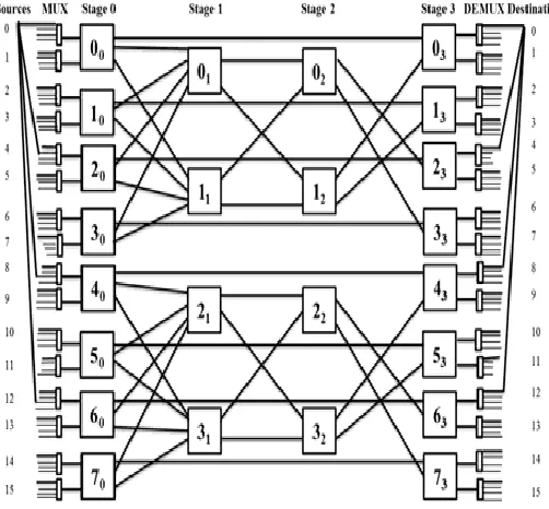
each SE in stage 0, stage 1, and stage 2 to stage (n-1) is 2×3, 4×2 and 2×2 respectively. RISEN of size 16×16 is shown in Fig. 1.
Fig. 1. Reliable Irregular Shuffle Exchange Network (RISEN)
RISEN consists of two identical sub-networks, which are denoted by Ga.where a=0 or 1, based on the most significant bit (MSB) of the destination address. If MSB is 0, then half of the source-destination terminals falls into the G0 and the others having MSB 1 fall into G1. For example, in Fig. 1, SE 00, 10, 20,
30 belonging to stage 0 of a subnetwork (G 0
) form a conjugate subset, switches 00 and 20 form one conjugate pair, and
switches 10 and 30 form another conjugate pair. Each
subnetwork is associated with all sources and all destinations with the help of MUX and DEMUX respectively. The SEs of each stage is connected with SEs of the next stage through links. The Link connection pattern from source to destination is as follows:
(1) Link Connections at Source:
Each source is connected with four multiplexers (MUX) as follows:
(i) For each source Si, where i=0 to ((N/4)-1)
(a) First link connects to MUX (i)
(b) Second link connects to MUX (i+(N/4)) (c) Third link connects to MUX (i+(N/2)) (d) Fourth link connects to MUX (i+(3N/4)) (ii) For each source Si where i=(N/4) to ((N/2)-1)
(a) First link connects to MUX (i)
(b) Second link connects to MUX (i+(N/4)) (c) Third link connects to MUX (i+(N/2)) (d) Fourth link connects to MUX (i-(N/4)) (iii) For each source Si where i=N/2 to ((3N/4)-1)
(a) First link connects to MUX (i)
(b) Second link connects to MUX (i+(N/4)) (c) Third link connects to MUX(i-(N/2)) (d) Fourth link connects to MUX (i-(N/4))
(iv) For each source Si where i=(3N/4) to (N-1)
(a) First link connects to MUX (i)
(b) Second link connects to MUX (i-(3N/4)) (c) Third link connects to MUX (i-(N/2)) (d) Fourth link connects to MUX (i-(N/4))
(2) Link Connections at MUX:
The RISEN consists of N number of multiplexers (MUX) with size 4×1, range from 0 to (N-1). Each switch j0, where j=0 to
N/2-1, in stage 0 is connected with two MUX with following steps:
(a) First link connects to MUX (2j) (b) Second link connects to MUX (2j+1)
(3) Link Connections at stage 0:
Each SE in the middle stage is connected with four SEs of stage 0. We assume that the total number SE in stage 0 is divided into N/8 groups (Pq), where q=0 to N/8-1. Each the
group (Pq) consists of four SEs. Each SE of group (Pq) has 3
output links. Each SE j0 of stage 0 is connected with 3 output
links:
(a) First link connects to SE j(n-1) of last stage
(b) Second output link connects to SE (2q)1 of stage 1
(c) Third output link connects to SE (2q+1)1 stage 1
(4) Link Connections from stage 1 to stage (n-3):
In this step, stages m=1 to (n-3) are considered except the last middle stage. Each stage consists of N/4 number of SEs. There are N/8 groups (Pr) in each stage, where r=0 to (N/8-1).
Each group consists of two switching elements (SEs). Each SE of each group (Pr) has two output links. These output
connection links are as follows:
(i) The SE (k=2r)m of stage m has 2 output links:
(a) First link connects to SE (2r)m+1 of next stage
(b) Second link connects to SE (2r+1)m+1 of next stage
(ii) The SE (k=2r+1)m of stage m has 2 output links:
(a) First link connects to SE (2r)m+1 of next stage
(b) Second link connects to SE (2r+1)m+1 of next stage
(5) Link Connections from at stage (n-2):
In this case, when network size is N=16. There are N/4 switching elements (SE) in stage 2. Each switching element (SE) has two output links. There are two cases to determine the link connections of SE: (i) When SE is Even and (ii) When SE is Odd. A SE k2 at stage 2 is even SE if kmod2=0,
otherwise it is an odd SE.
(i) When SE kn-2 of stage (n-2 is even then the output link
connections are as follows:
(a) First link connects to SE (2k+2)(n-1) of last stage
(b) Second link connects to SE (2k+3)(n-1) of last stage
(ii) When SE kn-2 of stage (n-2) is odd then the output link
connections are as follows:
(a) First link connects to SE (2k-2)(n-1) of last stage
(b) Second link connects to SE (2k-1)(n-1) of last stage
(6) Link Connections at last stage (n-1):
The last stage (n-1) consists of N/2 number of SEs. Each SE jn-1 has 2 output links, where the range of j=0 to (N/2-1).
Therefore, the output link connections of each SE jn-1 of the
last stage are as follows:
2279 IJSTR©2019
(b) Second link connects to DEMUX (2j+1)
(7) Link Connections at DEMUX:
The link connections at DEMUX consist of following steps: (i) Each destination Di is connected with four DEMUX,
where i=0 to ((N/4)-1)
(a) First link connects to DEMUX (i),
(b) Second link connects to DEMUX (i+(N/4)) (c) Third link connects to DEMUX(i+(N/2)) (d) Fourth link connects to DEMUX (i+(3N/4))
(ii) Each destination Di is connected with four DEMUX,
where i=(N/4) to ((N/2)-1)
(a) First link connects to DEMUX (i)
(b) Second link connects to DEMUX (i+(N/4)) (c) Third link connects to DEMUX(i+(N/2)) (d) Fourth link connects to DEMUX (i-(N/4))
(iii) Each destination Di is connected with four DEMUX,
where i=N/2 to ((3N/4)-1)
(a) First link connects to DEMUX (i)
(b) Second link connects to DEMUX (i+(N/4)) (c) Third link connects to DEMUX(i-(N/2)) (d) Fourth link connects to DEMUX (i-(N/4))
(iv) Each destination Di is connected with four DEMUX,
where i=(3N/4) to (N-1)
(a) First link connects to DEMUX (i)
(b) Second link connects to DEMUX (i-(3N/4)) (c) Third link connects to DEMUX (i-(N/2)) (d) Fourth link connects to DEMUX (i-(N/4))
3
R
OUTINGS
CHEME OFRISEN
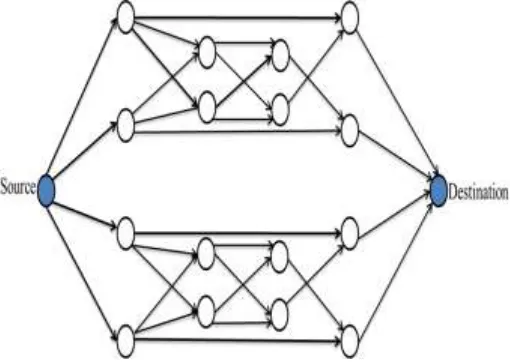
3.1 Redundancy Graph
The redundancy graph describes the all possible path between a source and destination address. The arrow symbol shows the alternate direct connections in the network to bye-pass the request in a similar stage if the switch in its next stage is busy or faulty. The RISEN network is not only cost-effective in comparison to existing IASEN-4 Networks but the performance measure in terms of the number of paths is also better. The redundancy graph representation of RISEN is shown in Fig. 2.
Fig. 2 Reliable Irregular Shuffle Exchange Network (RISEN)
3.2 Routing Algorithm
Routing procedure for a RISEN describes how a request from
any source travels through the different intermediate stages and reaches to a given destination. The RISEN is the self-routing network. It is assumed that each source-destination pair tries to use only one path at a time. It is considered that the source & switches have the capacity to detect faults in the switches to which they are connected. In RISEN, each source is associated with two switches in a subnetwork.
The idea of dynamic re-routing has been utilized to locate a substitute path from the present stage in case of a fault. In other words, if a fault occurs in any stage, a switching element (SE) in the previous stage will re-route data or message through an alternative path or link.
Let Si and Di are the source and destination addresses
respectively. Let binary representation of the source Si and
destination Di is as follows:
Si=s0, s1,…,sn-2,sn-1
Di=d0, d1,…,dn-2,dn-1, where i=0 to N-1
A source Si selects a particular subnetwork (G a
) based upon the most significant bit (MSB) of the destination address and attempts entry into the RISEN via its primary path. If the primary path is faulty (i.e. MUX or switch or both are faulty), the request is routed through the secondary path. For example, for source 0, SE (00) is the primary SE (PSE0) and
(20) is first alternate SE (FSE0) in stage 0 in subnetwork G 0
through its primary and secondary path respectively. SE 40
and 60 are second alternate SE (SSE0) and third alternate SE
(TSE0) for subnetwork G 1
in stage 0 through its primary and secondary path respectively. The first step of the routing of RISEN is to obtain the source address and its corresponding destination address.
Two algorithms are proposed in RISEN. Algorithm 2 is part of algorithm 1. In algorithm 1, if binary bits of source and destination address are the same and if the applicable SE of the first stage (SE0) and SE of last stage (SEL) are not faulty.
Then request is directly forwarded to the given destination via DEMUX from given source.
Algorithm 1: BEGIN
If (Si and Di are same)
{
if (SE0 and SEL are not faulty)
{
Send request from SE0 to SEL;
} else {
Algorithm 2; }
} else {
Algorithm 2; }
End
If the given source (Si) and destination addresses (Di) are
different then algorithm 2 is used. In algorithm 2, the request is forwarded from given source to the primary switching element (PSE0) of stage 0. If it is faulty then request is forwarded to
first alternate SE (FSE0) of stage 0. If FSE0 is also faulty then
2280 IJSTR©2019
www.ijstr.org faulty then request will be received by third alternate SE (TSE0) otherwise send the request to the primary SE of stage
1. If all of the SEs is faulty then drop the request. In the middle stage (k=1 to (n-2)) request is received by the primary switching element (PSEk) and if it is faulty then request is
received by first alternate SE (FSEk). If (FSEk) is also faulty
then drop the request otherwise send the request to the primary SE of next stage. In the last stage, the request is received by primary switching SE (PSEn-1). If it is faulty then
drop the request otherwise request is forwarded to a given destination through DEMUX.
Algorithm 2: At Stage 0:
if PSE0=FB //FB means busy or faulty node then FSE0
else if FSE0=FB
then SSE0 else if SSE0=FB
then TSE0
else if TSE0=FB
then drop the request else Send Request to PSE1
Stage (k=1 to (n-2)): // where n= log2N if PSEk== FB
then FSEk else if FSEk == FB then Drop the Request
else Send Request to PSEk+1 of Stage k+1 At Stage (n-1):
if PSE(n-1)== FB then Drop the Request
else Send Request to the destination
4
R
ELIABILITYA
NALYSIS ANDC
OMPARISON OFP
ROPOSED ANDE
XISTINGMIN
SIn this section, the reliability of IASEN-4 and RISEN is analyzed in terms of upper bound, lower bound of MTTF. Here are some presumptions for the study of the failure rates of the components which are used to evaluate the reliability of MINs: The failure rate of a component can be derived from its gate count. For 2×2 crossbar switches, the failure rate is λ (where λ is about 10–6 per hour) [13].
The failure of w×1size MUX and 1×w size DEMUX occurs independently and their failure rates are λm
and λd respectively. We assume that the failure rate of
w×1 MUX and 1×w DEMUX is wλ/4 i.e. λm= λd = wλ/4.
Let the failure rate of 2x3 switching element (SE2,3) is λ2,3 and
failure rate of 4x2 switching element (SE4,2) is λ4,2. Based on
the gate counts of the crossbar switch the failure rate of SE2,3
is λ2,3=1.5 λ and the failure rate of SE4,2 is λ4,2=2λ. According
to the adaptive routing scheme, let us assume that 2×2 size SE in the last stage and its associated 1×4 size DEMUX are in series system. So, we consider these three components as a single segment (SE2d). Based on the gate count let the failure
rate to this group λ2d=3λ.
4.1 Reliability of Proposed MIN (RISEN) (a) Optimistic or Upper Bound of RISEN
In RISEN, two same size (4×1)MUX are linked to each source and every SE in the first stage has a conjugate pair. For the computation of upper bound, we suppose that RISEN is working as long as one of the two MUX linked to a source in a subnetwork is working and both components in a conjugate pair are not faulty [13][15].
So, we can state that regardless of whether the half of the
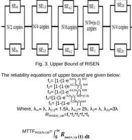
components or one sub-network is faulty and, even then RISEN is still working. The representation of upper bound of RISEN in terms of block diagram given in Fig. 3.
Fig. 3. Upper Bound of RISEN
The reliability equations of upper bound are given below: f1= [1-(1-e
-λmt
) 2] N/2 f2= [1-(1-(e
-λ2,3t
)2] N/4 f3= [1-(1-e
-λ4,2t
)2] N/8 f4=[1-(1-e
-λ2t
)2] N/8*(n-3) f5= [1-(1-e
-λ2dt
)2]N/4
Where, λm= λ, λ2,3= 1.5λ, λ4,2= 2λ, λ2= λ, λ2d=3λ
RRISEN_UB=f1*f2*f3*f4*f5
MTTFRISEN-UB=
(b)Pessimistic or Lower Bound of RISEN
To determine the pessimistic or lower bound of RISEN, it is assumed that the RISEN is failed whenever more than one conjugate pair (either switch or loop) has a faulty element or more than one conjugate switch in the last stage fails [13][15]. At the input side of proposed MIN, routing algorithm doesn’t consider the MUX to be an integral part of 3×3 SE [3] [15]. If two MUX are grouped with each SE and assigned them a series system (SE3m).The failure rate of SE3m is λ3m=3.5λ. As
long as at least one of the two MUX attached to a SE is working, the SE can still be used for routing[3][15]. The reliability block diagram of RISEN is shown in Fig. 4.
Fig. 4. Lower Bound of RISEN
The reliability equations of lower bound are given below: f1 = [1-(1-e
-λ3mt
)2]N/8 f2 = [1-(1-e
-λ4,2t
)2]N/8 f3 =[1-(1-e
-λ2t
)2]N/8*(n-3) f4=[1-(1-e
-λ2dt
) 2]N/8 RRISEN_LB=f1*f2*f3*f4
RISEN_UB
(t) dt
2281 IJSTR©2019
www.ijstr.org MTTFRISEN_LB =
4.2 Reliability of Existing MIN (IASEN-4) (a)Optimistic or Upper Bound of IASEN-4
For the calculation of upper bound of IASEN-4, we used the same above mentioned procedure that is used to calculate the upper bound of RISEN. The reliability block diagram of MTTF optimistic or upper bound of the IASEN-4 is shown in Fig. 5
Fig. 5. Upper Bound of IASEN-4
Reliability equations for upper bound MTTF: f1= [1-(1-e
-λmt
)2] N/2 f2= [1-(1-(e
-λ2,3t
)2] N/4 f3= [1-(1-e
-λ4,2t
)2] N/8*(n-3) f4= [1-(1-e
-λ2dt
)2]N/4
Where, λm=λ; λ2,3=1.5λ; λ4,2=2λ; λ2d=3λ;
RIASEN-4_UB=f1*f2*f3*f4
MTTFIASEN-4_UB =
(b) Pessimistic or Lower Bound of IASEN-4
For the calculation of MTTF lower bound of IASEN-4, we applied the same procedure that we used to calculate the MTTF lower bound of RISEN which is mentioned above. The reliability block diagram of lower bound of the IASEN-4 is shown in Fig. 6.
Fig. 6. Lower Bound of IASEN-4
Reliability equations for lower bound MTTF: f1 = [1-(1-e
-λ3mt
)2]N/8 f2 = [1-(1-e
-λ4,2t
)2]N/8*(n-4) f3 = [1-(1-e
-λ2dt
)2]N/8 Where, λ4,2=2λ, λ2d=3λ, λ3m=3.5λ
RIASEN-4_LB=f1*f2*f3
MTTFIASEN-4_LB =
The results of MTTF reliability equations have been given below in Table 1.
TABLE I. MTTF OF RISEN AND IASEN-4 FOR DIFFERENT
NETWORK SIZE
IASEN-4_UB IASEN-4_LB RISEN_UB RISEN_LB
4.9976 4.998 4.998 4.9984
4.9947 4.9957 4.9961 4.9968
4.9885 4.9904 4.992 4.9933
4.9752 4.9791 4.9836 4.986
4.9468 4.9546 4.9664 4.9714
4.8873 4.9026 4.9313 4.9412
The comparison graphs of MTTF upper bound and lower bound of existing (IASEN-4) and proposed (RISEN) MINs are shown in Fig. 7 and Fig. 8 respectively.
Fig. 7. MTTF Upper Bound Comparison of RISEN and IASEN-4
Fig. 8. MTTF Lower Bound Comparison of RISEN and IASEN-4
5
C
OSTA
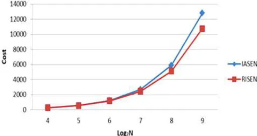
NALYSISIn order to estimate the cost of a MIN, it has been assumed that the cost of a switch is proportional to the number of crosspoints within that switch [15]. Therefore, for example, a 2×3 switch has 6 units of hardware cost and 4×1 MUX has 4 units of hardware cost. Thus, RISEN has the cost of N (12+n). The cost analysis for the proposed RISEN and existing IASEN-4 is given in Table 2.
TABLE II. COST FUNCTIONS FOR NETWORKS
Network Cost
IASEN-4 N(7+2n)
RISEN N(12+n)
From Fig. 9 it’s clear that RISEN and IASEN-4 both are having comparable cost.
IASEN-4_UB
(t)
dt
IASEN-4_LB
(t)
2282 IJSTR©2019
www.ijstr.org Fig. 9. Cost Comparison of RISEN and IASEN-4
7
C
ONCLUSIONThe general objective of designing irregular multistage interconnection networks is high reliability, fault tolerance and good performance even within the presence of faults. We provide a generalized structure (link connection formula for each stage) of RISEN which is rarely discussed in any irregular MINs. RISEN is a progressively re-routable network that gives various paths of variable lengths between a source and destination address. The upper and lower bound reliability analysis demonstrates that proposed RISEN is more reliable than existing IASEN-4. It has been seen that RISEN provides more paths than IASEN-4 between any source-destination pair and it will engage a bigger range of requests even under faults.
A
CKNOWLEDGMENTI would like to thank editor and the reviewers for their productive comments. I would also thank my guide Prof. Nipur Singh, my family, and Bhaiya ji who have been a pillar of strength for me and without whose encouragement none of this would have been possible.
R
EFERENCES[1] X. Jiang, A. Pattavina, and S. Horiguchi, “Strictly nonblocking f-cast photonic networks,” IEEE/ACM Trans. Netw, vol. 16, no. 3, pp. 732-745, 2008.
[2] F. Bistouni, and M. Jahanshahi , “Improving the reliability of the Benes network for use in large-scale systems,” Microelectron. Reliabil., Vol. 55, no. 3, pp. 679-695, 2015. [3] P. K. Bansal, R. C. Joshi and Kuldip Singh, “On a Fault-Tolerant Multistage Interconnection Network,” Computers Elect. Engg, Printed in Great Britain, vol. 20, no. 4, pp. 335-345, 1994.
[4] F. Bistouni, and M. Jahanshahi, “Improved extra group network: a new fault-tolerant multistage interconnection network,” J. Supercomput., vol. 69, no. 1, pp. 161-199, 2014.
[5] R. He, and J. G. Delgado-Frias, “Fault tolerant interleaved switching fabrics for scalable high-performance routers,” Parallel Distribut. Syst. IEEE Trans., vol. 18, no. 12, pp. 1727-1739, 2007.
[6] C. C. Fan, and J. Bruck, “Tolerating multiple faults in multistage interconnection netsworks with minimal extra stages,” Comput. IEEE Trans., vol. 49, no. 9, pp. 998-1004, 2000.
[7] X. Shen, F. Yang, and Y. Pan, “Equivalent permutation capabilities between time-division optical omega networks
and non-optical extra-stage omega networks,” IEEE/ACM Trans. Netw., vol. 9, no. 4, pp. 518-524, 2001.
[8] Y. Yang, and J. Wang, “Routing permutations on baseline networks with node-disjoint paths,” Parallel Distribut. Syst. IEEE Trans., vol. 16, no. 8, pp. 73746, 2005.
[9] A. Sheta, “Parameter Estimation of Software Reliability Growth Models by Particle Swarm Optimization,” ICGST-AIML Journal, vol. 7, no.7, june, pp.55-61, 2007.
[10]Bansal, P.K., Joshi, RC., Singh, K. and Shha, G.P. “Fault-Tolerant Augmented Baseline Multistage Interconnection Network,” Proc. International Conference IEEE. TENCON 91, INDIA, pp. 200-204, 1991.
[11]J. Nathaniel Davis, William, Tsun-yuk Hsu and H. J. Siegel, “Fault location techniques for distributed control interconnection networks,” IEEE Transactions on Computers, vol. C-34, no.10, 1985.
[12]V. P. Kumar and S. M. Reddy, “Design and analysis of fault-tolerant multistage interconnection networks with low link complexity”, Proceedings of 12th International Symposium on Computer Architecture, pp. 376-386, 1985. [13]Bansal, P. K., Joshi, R.C., Singh, K., “On a Fault Tolerant
Multistage Interconnection Network”, International Journal of Electronics and Electrical Engineering, 20(4), pp. 335-345, 1994.