Liquid-Mediated Solid-State
Metathesis Reactions
Daniel Morrison
ProQuest Number: U642239
All rights reserved
INFORMATION TO ALL USERS
The quality of this reproduction is dependent upon the quality of the copy submitted.
In the unlikely event that the author did not send a complete manuscript and there are missing pages, these will be noted. Also, if material had to be removed,
a note will indicate the deletion.
uest.
ProQuest U642239
Published by ProQuest LLC(2015). Copyright of the Dissertation is held by the Author.
All rights reserved.
This work is protected against unauthorized copying under Title 17, United States Code. Microform Edition © ProQuest LLC.
ProQuest LLC
789 East Eisenhower Parkway P.O. Box 1346
L
Abstract:
A variety o f metathetical reactions have been carried out in a liquid medium to explore the variety and depth o f such reactions, A comparison with the similar solid-state reactions gives a clear indication o f the differences and similarities between the two alternate routes. The fact that these reactions go to completion at all is interesting in that the conditions employed are very mild and do not employ any "forcing" means to induce reaction.
Main group and transition metal sulphide, selenide and telluride and transition metal phosphide, arsenide and antimonide binary and ternary compounds were synthesised and characterised. An in-depth investigation into the synthesis and characterisation o f the chalcopyrite CuInEj (E = S, Se, Te) family o f ternary compounds has also been carried out with a specific focus on liquid variation, reaction duration and temperature and annealing treatment. Solid-state metathesis synthesis o f CuInEj was also carried out for comparison purposes.
I suppose that when the bees crowd round the flow ers it is fo r the sake o f honey that they do so, never thinking that it is the dust which they are carrying from flow er to flow er which is to render possible a more splendid array offlowers, and a busier crowd o f bees, in the years to come. We cannot, therefore, do better than improving the shining hour in helping forw ard the cross-fertilisation o f the sciences.
Lecture given at Cambridge, May 14, 1878 while directing a demonstration o f the telephone
IL Table o f Contents:
Section________________________________________________________ Page Number
I. Abstract ... 2
n.
Table o f Contents...4
m . List o f Figures ... 8
IV. List o f T a b le s ... 11
Y. List o f Abbreviations... 12
VI. Acknowledgements ... 13
1. Introduction... 14
1.1 Preamble ... 14
1.2 Combustion S y n th esis... 15
1.3 Metathesis R eaction s... 18
1.4 Solid-State Metathesis Reactions... 19
1.4.1 General Introduction ... 19
1.4.2 Theory ... 21
1.4.3 Previous W o r k ... 23
1.4.4 D raw backs...25
1.5 Liquid-Mediated Metathesis ...27
1.5.1 General Introduction ... 27
1.5.2 Previous W o r k ...29
1.5.3 Final W o rd ...35
1.6 Solid-Liquid M etathesis...36
1.7 Other Metathesis-like Reactions ... 37
1.8 Nanoparticulates ... 39
1.9 Introduction C onclusions... 41
2.1 Introduction... 42
2.1.1 Thin Films ... 42
2.1.2 Bulk M aterials...43
2.2 Results - Synthesis and Characterisation...46
2.2.1 First Row Transition Metals - Titanium, Vanadium, Iron, Cobalt & N ic k e l... 46
2.2.1.1 X R D D a ta ...46
2.2.1.2 ED AX D a ta ... 47
2.2.1.3 Particle Morphology & Sizes ... 49
2.2.2 Group 11 - Copper & S ilver... 50
2.2.3 Group 12 - Zinc, Cadmium & M ercury... 54
2.2.4 Group 13 - In d iu m ...59
2.2.5 Group 14 - Tin & Lead ...62
2.2.6 Group 15 - Antimony & A r se n ic ... 67
2.3 Discussion ... 70
2.3.1 Nature o f Reactants and L iq u id ... 70
2.3.2 Reaction Sp eed ... 71
2.3.3 Reaction Pathway and Completion ...71
2.3.4 Crystallinity...73
2.3.5 Crystallite S i z e s ...74
2.3.6 Annealing & Crystallite Size Control ... 74
2.3.7 Redox Chemistry & Phase Control ...79
2.3.8 Mixed Temaiy C halcogenides...80
2.3.9 Transition M eta ls... 82
2.3.10 Comparison with Liquid Ammonia M etathesis...84
2.4 Precursor Synthesis ...86
2.4.1 Ampoule Synthesis ...86
2.5 Experimental ... 91
2.5.1 Reaction M ethodology... 91
2.5.2 X-ray Powder Diffraction ...92
2.5.3 Infra-red Spectroscopy... 92
2.5.4 Raman Microscopy ...92
2.5.5 Ultraviolet / Visible Spectroscopy... 93
2.5.6 Annealing / H eatin g... 93
2.5.7 Scanning Electron Microscopy ... 93
2.5.8 Energy-Dispersive Analysis by X-rays ... 93
2.5.9 Glassware... 94
2.5.10 S o lv e n ts ... 94
2.5.11 Experimental Manipulations ... 95
2.5.12 R eagents... 95
3. Transition Metal Pnictides... 96
3.1 Introduction... 96
3.2 Results - Synthesis and Characterisation... 99
3.2.1 Group 4 - Titanium ...99
3.2.2 Group 5 - Vanadium ... 100
3.2.3 Group 8 - Iron ... 102
3.2.4 Group 9 - Cobalt ... 103
3.2.5 Group 10 - Nickel ... 107
3.2.6 Group 11 - C opper... 115
3.2.7 Group 1 2 - Z i n c ... 117
3.3 Discussion ... 119
3.3.1 Implications o f Metathetical (Salt) B alan cin g... 119
3.3.2 Comparison with Other Liquid M ed ia ... 120
3.3.4 Redox C hem istry... 123
3.3.5 Ternary Product S yn th esis... 125
3.3.6 Ternary Titanium P n ictid e... 127
3.4 Experimental ... 130
4. Ternary Chalcopyrites ... 131
4.1 Introduction... 131
4.2 Results - Synthesis and Characterisation... 132
4.2.1 Copper Indium Sulphide ... 132
4.2.2 Copper Indium Selenide... 135
4.2.3 Copper Indium T ellu rid e... 138
4.2.4 Copper Gallium Sulphide ... 141
4.2.5 Different Liquids ... 143
4.2.6 Different Treatments ... 146
4.3 Discussion ... 148
4.3.1 Different Liquids ... 148
4.3.2 Reaction Pathway... 152
4.3.3 Solid-State vs. Liquid-Mediated Metathesis ... 154
4.3.4 Halide Effect ... 156
4.3.5 Gallium R ea ctio n s... 157
4.4 Experimental ... 159
5. C o n clu sio n s... 160
IIL List o f Figures:
Number________________________________________________________Page Number
1-1 Elemental V5. Ionic Pathway ... 22
2-1 XRD pattern ofNiSggg, annealed... 48
2-2 XRD pattern o f NiSej, annealed... 49
2-3 XRD pattern o f AgzSe...51
2-4 XRD pattern o f AgzS...52
2-5 XRD pattern o f Cu^ ^gSe...53
2-6 XRD pattern o f ZnS... 55
2-7 XRD pattern o f CdS... 56
2-8 Raman spectrum o f CdS... 56
2-9 XRD pattern o f HgS (metacinnabar)... 57
2-10 Raman Spectrum o f HgS (cinnabar)... 58
2-11 SEM o f CdSo.5 Sco 5, annealed... 58
2-12 SEM o f ZnSe, annealed...58
2-13 XRD pattern for hijOj, annealed... 60
2-14 SEM o f L12O3, annealed... 61
2-15 SEM o f hijTej unannealed...61
2-16 SEM o f L12S3, annealed... 61
2-17 Raman spectrum o f SnS2, before annealing... 63
2-18 Raman spectrum o f SnS, before annealing... 64
2-19 XRD pattern for SnS2 (bemdtite) unannealed... 64
2-20 XRD pattern for SnS (herzenbergite) unannealed... 65
2-21 XRD pattern for PbS (galena)... 65
2-26 XRD Spectrum o f AgjS before and after annealing... 73
2-27 Crystallite Size vs. Annealing Temperature (lUjSj)... 75
2-28 XRD pattern o f ZnS as-synthesised...76
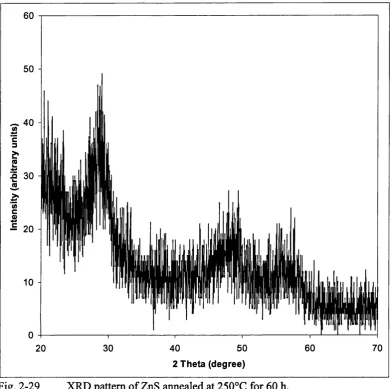
2-29 XRD pattern o f ZnS annealed at 250°C for 60 h... 77
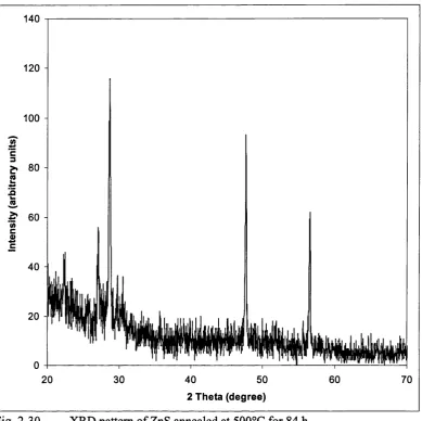
2-30 XRD pattern o f ZnS annealed at 500°C for 84 h... 78
2-31 Crystallite Diameter vs. Annealing Temperature (Z n S )... 79
2-32 Crystallite Size vs. Annealing time at 500°C (In2S3) ... 79
2-33 XRD o f CdSo 5 Soq.s from 1:1:1 reaction... 82
3-1 XRD pattem for exposed product from TiCl3 +NagAso sSbo 5... 100
3-2 XRD pattern o f shiny, metallic component, showing arsenic only 103 3-3 XRD pattern o f CoAs, annealed... 104
3-4 XRD pattern o f CoSb, annealed... 105
3-5 VSM hysteresis loop for CoSb... 106
3-6 SEM o f CoAs, annealed... 107
3-7 XRD pattern for NiAs (nickeline)... 109
3-8 XRD pattern for NiSb (breithauptite)... 109
3-9 XRD o f TemaryNiAso.25Sbo.75 [101] peak...110
3-10 XRDs o f Temary NiAso.25Sbo.75 & NiAso.5Sbo.5 [102] & [110] peaks I l l 3-11 VSM hysteresis loop for NiSb...112
3-12 SEM o f NiAso.5Sbo.5 unaimealed...113
3-13 SEM o f NiAso 5Sbo 5 unannealed... 113
3-14 SEM o f NiAso5Sbo 5, annealed...114
3-15 XRD pattern for CU3P from CUCI2... 116
3-16 XRD pattem for Na3Aso 5Sbo 5... 127
4-1 [215] & [312] peaks o f CuInS2 from CuBr & CUCI2 by LMM... 133
4-2 XRD pattem for CuInS2 from CuBr by LMM... 134
4-3 XRD pattem o f CuInSe2 from CUCI2 by SSM... 136
4-5 XRD pattem for CuInTcj from C11CI2 by LMM, annealed... 140
4-6 XRD pattem for CuInTej from CuBr by SSM ... 141
4-7 XRD pattem for Cu^ j^sS (digenite) intermediary... 142
4-8 XRD pattem for CuGaSj from CuClj... 143
4-9 SEM o f CuInSj from pyridine, annealed... 145
4-10 SEM o f CuInSj from DCM, annealed... 145
4-11 XRD o f CuInSj from room-temperature reaction, annealed... 146
4-12 XRD o f CuInSj annealed at 500°C for 5 min... 147
4-13 SEM o f CuInSj from ether... 149
4-14 SEM o f CuInSz from DCM... 149
4-15 SEM ofCuInSzfrom THE... 149
4-16 SEM o f CuInSj from hexane... 150
4-17 SEM o f CuInSj from toluene... 150
4-18 SEM o f CuInSj from pyridine... 150
4-19 XRD o f CuGaSj unannealed, showing CuS (covelite) only... 153
4-20 XRD o f CuGaS2 after annealing... 154
4-21 SEM o f CuInS2 from toluene, annealed... 155
IV. List o f Tables:
Section________________________________________________________ Page Number
1 Product and XRD data for transition metal chalcogenides ... 47
2 Product and XRD data for silver and copper chalcogenides...52
3 Product and XRD data for zinc, cadmium and mercury chalcogenides. . . . 54
4 Product and XRD data for hi2E3 (E = O, S, Se, T e ) ...59
5 Product and XRD data for zinc, cadmium and mercury chalcogenides. . . . 62
6 Product and XRD data for SbzEg (E = O, S, Se, Te) ...69
7 Chalcogenide and Pnictide Precursor M a s s e s ...87
8 Solvents and Drying Conditions ... 94
9 X-ray powder diffraction data for CuInS2, after annealing at 5 0 0 ° C ... 132
10 X-ray powder diffraction data for CuInSc2, after annealing at 500°C . . . 135
11 X-ray powder diffraction data for CuInTc2, after annealing at 500°C . . . . 139
V.
List o f Abbreviations:
XRD Powder X-ray Diffraction
SEM Scanning Electron Microscopy, Scanning Electron Micrograph ED AX Energy-Dispersive Analysis by X-rays
IR Infrared
SSM Solid-State Metathesis
VL Acknowledgements:
I would most o f all like to thank my supervisor Dr. Ivan Parkin for all his supervision and discussions. I would also like to thank Dr. Claire Carmalt for her support, useful discussion and advice. I would like to thank Kevin Reeves o f the Institute o f Archaeology for his helpfulness, patience and perseverance in putting up with me and my questions. I would like to thank the Committee o f Vice-Chancellors and Presidents for an Overseas Research Studentship.
1,
Introduction:
1.1
Preamble:
The synthesis o f solid compounds from the elements or other solid precursor compounds has been carried out since before recorded history, as witnessed by the finds o f ceramic pots and brass and iron implements. Since the starting materials in traditional solid-state syntheses frequently have high melting points and low vapour pressures, overcoming diffusion barriers is an important consideration. Conventional ceramic or metallurgical synthetic techniques therefore require high-temperature ovens and prolonged and complex regimes o f heating and cooling cycles, interspersed with manual grinding, to arrive at a final product in the desired state.
In modem times many methods have been devised to overcome these difficulties. Since the reaction rate is directly proportional to the surface contact between particles, high surface area precursors have been employed from ball milling, grinding or precipitation in order to speed up reaction times. Using molten fluxes or high-temperature solvents, such as molten Sn, Bi or halide salts, as media for solid-state reactions has also been used to circumvent the solid-state diffusion barrier. This can be most simply defined as the temperature above which the rate o f diffusion o f one atom through another atom matrix becomes significant.
1.2
Combustion Synthesis:
The combustion synthesis, or more specifically, the self-propagating high-temperature synthesis (SHS) method was pioneered in Russia in the 1960's. This method uses the highly exothermic redox reaction between a fuel and an oxidiser to form a product o f interest. The most studied compounds are refractory materials, that is, borides, carbides, nitrides, silicides, ceramics, intermetallics and oxide materials. More recently, some electronic engineering materials such as superconductors (3Cu + 2Ba0 2
+ Î/2Y2O3 -> YBa2Cu307_J^ ferroelectric and magnetic materials (Ba0 2 + 5Fe203 + 2Fe + 0 2 ^ BaFei2 0i9)^ have been synthesised by SHS. To date over 500 different compounds have been synthesised by SHS, and many products are made on a commercial basis in Russia. A general SHS reaction is shown in Eq. 1-1 :
nA + mB A^B^ (Elemental SHS) Eq. 1-1
where A is a fuel like Ti, Zr, Hf, Ta, B, Be or Si, and B is an oxidizer like B, C, N, O, S, Si or Se. Other SHS reactions can involve compounds as precursors which form a single product, as in Eq. 1-2,
Ba0 2 + 5Fe203 + 2Fe + O2 BaFei2 0i9 Eq. 1-2
or can involve multiple precursors and multiple products to form composites, as in Eq. 1-3:
Ti0 2 + B2O3 + 5Mg TiB2 + 5MgO Eq. 1-3
than ~ 1500°C. This can be accomplished by laser irradiation, resistance coil heating, electrical arcs or chemical oven means. After reaction initiation, the reaction proceeds
via a reaction wave which travels through the reaction pellet in a self-propagating manner reaching temperatures from 1500 to 4900 K. This wave usually passes through the reaction mixture within a few seconds. A value called the adiabatic temperature (T^J, which is a measure o f the reaction exothermicity, is also a measure used to predict whether a particular reaction will be self-propagating or not. It has been determined that i f the Tad is greater than ~ 1800 K the reaction will be self-propagating. Other important factors that are important in SHS reactions are particle size and shape o f the reactants, ignition method, stoichiometric ratio, green mixture density, that is, the density o f the pellet before ignition.
Various methods have been employed to lower this ignition temperature. Mechanical alloying, that is, utilising ball milling to impact the reacting particles, thus increasing surface area, is one such method. Field activated combustion synthesis uses an applied voltage to activate certain reactions. The field direction can also affect the synthesis wave velocity.
SHS is advantageous over conventional routes in that it is very simple, very fast, energetically efficient in that it only requires initiation, after which it is self-sustaining, and it yields products o f high-purity. An interesting factor o f SHS is that the green mixture can be pressed into any shape and then ignited and the product will maintain the shape o f the green mixture. Being a high-temperature method, the products are invariably the thermodynamically stable phases. However, given the rapid heating and cooling rates, there is the potential for metastable phases to be formed.
product is synthesised.
1.3
Metathesis Reactions:
The focus o f this thesis is on a set o f reactions that have been called metathesis or metathetical reactions. Being a relatively new development in inorganic chemistry, these reactions are not generally known. Therefore, it is essential to give an introductory explanation and some general properties/characteristics o f these reactions.
Metathesis reactions are a subset o f the combustion synthesis methods described above but rather than using elemental or oxide precursors, they use metal halides and alkali metal main group compounds. A general definition o f a metathesis reaction is, a reaction where there is an exchange o f chemical “partners” between the reactants involved, with each other, to form the desired product and a co-produced salt. This is shown generally in Eq. 1-4:
AB + CD -> AD + BC Eq. 1-4
Some specific examples are shown in Eqs. 1-5 to 1-8:
TiClj + NagP Tip + 3NaCl Eq. 1 -5
TiBr^ +
2U2S
->
TiSz
+ 4LiBr Eq. 1-6
TÜ4 + ZCaCg T ie + 2Cal2 + C Eq. 1-7
STiCl^ + Al^Cg ->► 3TiC + 4AlCl3 Eq. 1-8
1.4
Solid-State Metathesis Reactions:
1.4.1 General Introduction:
Metathesis reactions which are performed between two reactants which are solids have become known as solid-state metathesis (SSM) reactions. SSM reactions offer an alternative to long, difficult and costly traditional materials processing techniques. SSM reactions require significantly less, and in some cases, no external energy input to go to completion. This low energy input requirement is due to the built-in chemical energy inherent in the system. The driving force o f the reaction is the heat o f formation and the heat o f crystallisation o f the by-product alkali or alkaline earth metal / halide salt. This can account for up to 90% o f the reaction energy.
SSM reactions involve the mixing o f the two reactants as powders and then placing them in a ceramic boat or glass or quartz ampoule. These reactions, while not requiring a large energy input for the reaction to proceed, do require a source o f initiation. Suitable initiation methods include contacting the reaction mixture with a hot filament, heating the reaction mixture in a furnace, grinding the reaction mixture vigorously and stirring the mixture lightly. In some rare cases even mere contact o f the reactants with each other is sufficient to initiate the reaction. The level o f severity o f initiation required is dependent on the nature o f the two reactants.
to vaporise the salt.
Solid-state metathesis reactions are interesting because they are so rapid. Conventional ceramic synthetic methods rely on high temperatures (>1200°C) and long reaction times (often days) in order to reach some appreciable solid-state diffusion rate o f the reacting species through the solids'*. The extraordinary speed o f completion o f SSM reactions has been attributed to the high internal temperatures reached at the time o f reaction, which in course leads to a molten flux o f the alkali/alkaline earth salt, which provides a ‘ liquid ’ medium in which atoms can diffuse much more rapidly than if they had to diffuse through a solid material.
One advantage o f SSM reactions is that, with variations, it is possible to get some control over reaction conditions and particle sizes compared with traditional ceramic syntheses^. Other than their rapidity, SSM reactions also offer the advantage that the product synthesised is already crystalline as synthesised. Thus there is no need for subsequent annealing step to induce crystallinity.
The products synthesised are typically o f high purity. The purity o f the product is directly controlled by the purity o f the precursors. In ceramic synthesis techniques that involve long timespans at elevated temperatures, there is often a problem with contamination o f the product with the material o f the container in which the ceramic is being sintered or synthesised. In SSM reactions, because the timespans are so short, there is no time for the diffusion o f the container material into the product.
Another potential issue is incorporation or cross-contamination o f the product with chloride residues. In all metathesis reactions the synthesised product is an intimate mixture o f the product and the co-produced salt. The purification o f the product is simply done by washing the product mixture with methanol, ethanol, water or some other liquid in which the co-produced salt is soluble. It has been seen repeatedly, in most metathesis reactions, that after washing o f the reaction product mixture, there is no detectable contamination o f the product with chloride.
Under the standard conditions used for most reactions, the reaction pathway follows a rapid temperature rise followed by a rapid cooling o f the reaction mass. When the reaction scale is increased, the subsequent smaller ratio o f surface area to volume leads to a greater self-insulation o f the reaction mass. This leads to the reaction mixture remaining at a higher temperature for longer. This leads to products o f higher phase purity and crystallinity. However it is also observed, in some cases, that, due to the greater temperature difference between the surface and centre, the reaction product was inhomogeneous from region to region.^ Another effect o f increasing the reaction mass was that in temary sulphide-selenides higher temperatures were obtained, leading to higher sulphur incorporation, due to the inherently different diffusion constants o f S and S e /
In SSM reactions it is possible to control the average particle size o f the product by judicious use o f an inert additive to act as a dilutant. This dilutant is usually the same salt as is produced in the reaction. The addition o f various mole equivalents o f dilutant to the reaction, given a constant mole amount o f reactants, leads to a larger reaction mass over which the same amount o f reaction heat has to be distributed. This therefore serves to lower the overall reaction temperature. Thus the formed product receives less heat per mole and less energy goes into crystal growth in the product.
Since SSM reach high temperatures they generally produce thermodynamic phases, but in some cases it is possible get metastable, quenched high-temperature phases, which may be desired or interesting.^
1.4.2 Theory:
these two extremes. In both routes the assumption is that salt formation occurs first. In the elemental route, the metal and other reacting species are reduced/oxidised to the elements, which then under the reaction conditions combine to form the product, perhaps undergoing the proper redox process to the appropriate form for the product. In the ionic route, the reacting species retain their charges and combine to form the product directly. There is some scope for redox chemistry in the ionic pathway as well, as shown figuratively by the excess E in Fig. 1-1. This is in such cases where the charges in the product do not match those o f the precursors.
Elemental Route
nAX + M + n/mE ^
Precursors MXn + n/m A„B
nAX + ME + (n/m~l)E
Fig. 1-1 Elemental v^. Ionic Pathway
Ionic Route
nA X + + n/mE'”'
This seems to strongly suggest that a molten medium is necessary for a rapid, unassisted reaction to occur/ While there are more subtle factors that affect propagation, this indicator is useful as a relatively accurate predictor o f propagation.
These indicators o f self-propagation are only an issue for those reactions initiated by a hot filament. Reactions that do not self-propagate may still be caused to react by providing external energy input such as heating the reaction mixture in an ampoule in an oven or providing added energy from a second simultaneous chemical reaction.
1.4.3 Previous Work:
Since the beginning o f the 1990s, the scope and implications o f solid-state metathesis reactions have been explored in quite some detail. The groups off. P. Parkin and R. B. Kaner have been the two most prolific in this area. It can be said, with almost no exaggeration, that virtually every binary compound o f a main group metal, transition metal or lanthanide element with a main group element in the periodic table has been made.* Attempting to summarise all the results would only lead to more confusion than enlightenment. I will endeavor to touch upon all the prominent observations and conclusions that have been discovered through the work o f these groups. Reference 8
is an excellent review o f solid-state metathesis reactions up to 1996.
nitrides are obtained. For chromium, a mixture o f CrN and CrjN are obtained. Lanthanides readily form LnN phases.
Phosphides, arsenides and antimonides have also been synthesised by SSM. For these reactions Na^E (E = P, As, Sb) is the pnictide precursor. Phosphides o f the formula MP are the predominant product for reactions o f metal halides and Na^P. Reactions o f Na^As form predominantly M As, but there are a number o f cases where varied and mixed phases are observed. Reactions ofNa^Sb sees mainly MSbz products but many reactions result in metal antimonide and antimony metal. This trend continues when one uses Na^Bi which results in only metal and bismuth. This trend shows that as the co-reactant element gets heavier the reaction mechanism favours the elemental recombination pathway but lacks the energy to complete the recombination.
Metal oxide formation from SSM reactions using LizO, Na2Û2 and NajO has formed a wide variety o f compounds. Most reactions formed metal oxides with the metal unchanged in oxidation state. When LijO is used, in a number o f cases, there is lithium incorporation into the product leading to the formation o f lithium metal oxides.
Sulphides, selenides and tellurides have been synthesised using NagE (E = S, Se, Te) as the chalcogenide precursor. For most transition, main group and lanthanide metal halides, single-phase sulphide formation occurs after both filament and oven initiation. Most o f these reactions maintain the oxidation state o f the metal precursor. Less work has been done on selenides and tellurides but for main group metals the products show the same trend as for sulphides. An interesting observation is in reactions aiming to form temary metal sulphur-selenides. It was noted that the product did not contain the chalcogenide ratio o f the starting materials. The products were enriched in the more volatile sulphur component presumably due to its increased mobility during the brief period o f reaction heat.
shown some promising results/
1.4.4 Drawbacks:
SSM reactions have been shown to be versatile, useful reactions that allow the rapid and facile synthesis o f a number o f compounds. However, like all things, there are always drawbacks and limitations to the reaction methodology. These limitations are derived from the same factors that make the reactions interesting and successful.
One problem encountered has been the result o f the very high temperatures reached during the short time o f the SSM reaction. For most cases these high-temperatures contribute to the completion o f the reaction and the subsequent self annealing, however in some cases the temperatures reached are sufficient to first form, and then decompose, the desired product. For example in the following reaction the product is formed intermediately but is almost immediately decomposed;
ZLi^N + WClg -> 6LiCl + ‘/2N2+ { W N } * + Eq. 1-9
One method devised for counteracting such an effect is the addition o f an inert heat sink or dilutant, as mentioned above, to the reaction mixture in order to attempt to control the violence o f the reaction. The inert salt absorbs the reaction energy so that less energy goes into heating the products. This has enabled some formerly inaccessible products to be synthesised.
In SSM reactions the products formed are often the thermodynamic product because the high temperatures reached allow the reaction to go to completion. In other cases the reaction pathway is a very quick rise in temperature followed almost immediately by a very quick cooling to ambient temperatures. This leads to the product synthesised being a quenched-in kinetic or meta-stable phase.
products is that there can be a high defect proportion in the product. Like any quenching procedure the defect concentration at the high temperature is quenched in on cooling rapidly. Likewise there has been observed considerable lattice strain in such quenched products.
1.5
Liquid-M ediated Metathesis:
Simultaneous to the development o f solid-state metathesis reactions, there was some interest in performing metathesis reactions in a non-reacting hquid medium. There doesn’t seem to be any clear consensus on a name for this type o f reaction, but various names are used such as solution-phase metathesis, solvent-based metathesis and solvothermal synthesis (providing that heat is applied) have all been used in the literature. For this thesis the term liquid-mediated metathesis (LMM) will be used. Due to the nature o f the reactions and reactants it will become clear from the ensuing discussion that it is difficult to give a name to these reactions which is as truthful as possible, since for the majority o f reactions it is unclear whether, and if so, to what extent, the liquid acts as a solvent (species actually dissolved) and to what extent it is merely a liquid medium.
1.5.1 General Introduction:
As it has been described above, the solid-state metathesis reaction method employs rather severe reaction conditions. It has been sought to employ milder conditions in order to gain a greater grasp on control o f the reaction conditions and thus the reaction products. One such approach is the liquid-mediated metathesis reaction mechanism. The reasoning is as follows:
To perform metathesis reactions in a liquid is seen as comparable to the use o f an inert salt additive with the difference that a liquid is seen as a better heat sink. It is also usual to use an amount o f liquid which is 1 0 0 to 2 0 0 mole equivalents o f the reactants, whereas inert salt additions are from 2 to 20 mole equivalents. A stirring liquid reaction medium would also be a more efficient dissipator o f the exothermic reaction energy than a solid salt in which the heat dispersion would be dependent on the heat diffusion through the static salt.
volume o f liquid present, the maximum temperature possible for the reaction (at ambient pressure) is the boiling point o f the liquid. While the addition o f an inert salt to an SSM reaction does reduce the maximum temperature o f a reaction, this still only amounts to a reduction from ~ 1600K to ~ 900K for a 20:1 dilution (for M0CI5+ Na2S) which is still far higher than most liquids’ boiling points.
Another role that the liquid can play is as a particle dispersant. In a stirred reaction scheme the reactant particles will be separated by the stirring liquid and will be kept disperse, unlike in SSM reactions where the reactants are tightly packed together. Contact between particles does still occur in the stirring action in the reaction vessel. The liquid can also act to renew the surfaces o f the reacting particles to further promote the reaction.
There are numerous reasons to cany out research in this field o f liquid-mediated metathesis reactions. One is that there has not been very much work in this area. The majority o f papers focus on II-IV and m -V semiconducting materials. While these are important technological materials, the intense focus on these materials means that there is very little known about the potential and limitations o f liquid-mediated metathesis reactions in general. One motivation is that it will be possible to attain greater control o f the product properties due to the relatively mild reaction conditions.
1.5.2 Previous Work:
If we consider reactions that are strictly within what we have defined as metathesis reactions, that is a metal halide and an alkali metal main group compound, then there has been very httle reported literature on liquid mediated metathesis reactions as compared with the volume o f work on SSM reactions.
One o f the earliest papers reports the synthesis o f a variety o f MSj compounds (M = Ti, Zr, Hf, V, Mo, Nb and Ta). Chianelli and D in e se m p lo y ed 10 mmol amounts o f MCI4 (MCI5 for Nb and Ta) in 30 ml amounts o f THF or ethyl acetate to which they add 20-40 mmol amounts o f LijS or Na2S in 30 ml o f the same solvent. The LijS or Na2S / THF or ethyl acetate mixture was a slurry rather than a true solution. This mixture was allowed to stir at room temperature for several hours to one day. The precipitate was collected and washed with the solvent used.
An alternate method was the use o f amine or ammonia sulphides or hydrosulphides. These were synthesised in situ by combining the organic solvent with the amine or ammonia and bubbling HjS through the solution. The reactions proceeded as in Eqs. 1-10 and 1-11.
MCI4 + 2A2S -> MS2 + 4ACI, or Eq. 1-10 LCI5 + VjAjS ->■ LS2 + 5AC1 + V2S , where Eq. 1-11 M = Ti, Zr, Hf, V, Mo
L = Nb, Ta. A “ Li, Na, NH4.
o f many o f these compounds, leading to inclusion compounds. Crystalline TiSj could be made by increasing the temperature o f the reaction to 65 °C. Annealing the amorphous product at 400°C yielded crystalline TiSj. Lastly, they report that the synthesis o f VS2
is only achievable using such a low-temperature technique as the one reported. VSj was previously thought not to exist, but this method allows previously inaccessible areas o f phase diagrams to be reached. There is no direct reference to the particle sizes obtained but there are XRD diagrams showing highly broadened peaks, which is commonly taken as a sign o f restricted particle size.
One thing that the authors noted in relation to the reagents used is that the nature o f the precursors seemed to influence the reaction rate significantly. They observed that when they used highly crystalline LijS orNsgS the reaction rate was significantly reduced when compared with poorly crystalline precursors. To make the reactions using crystalline precursors proceed at any reasonable rate it was necessary to heat the reactions. The highly crystalline precursors would not react with even neat TiCl^ while poorly crystalline precursors would react very violently with pure TiCl^. It was found that commercial LijS and NajS samples vary widely from batch to batch in their crystallinity, and they were forced to obtain X-ray diffraction patterns for each sample. They attempted to alleviate this by synthesising highly reactive LiHS from «-butyllithium and HjS. This represents an intermediate compound between H2S and Li2S or Na2S.
Kaner et al. report the synthesis o f CdTe, HgTe and Hgi_,^Cd,^Te from a liquid-mediated metathetical reaction. They poured 0.74 mmol Cdl2 in 50 ml o f oxygen-free MeOH and 0.74 mmolNa2Te in 50 ml oxygen-free MeOH simultaneously into a beaker contaning 30 ml o f oxygen-free MeOH all inside an argon-filled glovebag. The product precipitates within seconds and is filtered and washed with MeOH. The reactions were performed at room temperature and at 65°C.
5 to 20 nm size range. Annealing studies showed that moderate annealing at 100° for greater than 4 hours had a marked effect on crystallite size. The average particle size is shifted to between 5 and 7 nm, while the larger particle sizes are also enchanced, with a significant quantity o f particles now reaching 35 nm. Performing the reaction at 65°C shifts particle size to somewhere intermediate between the room-temperature synthesised product and the annealed product. It is reported that performing the synthesis at elevated temperatures does not affect the upper range o f particle sizes.
Kher and W ells‘S reported the synthesis o f GaAs and GaP by a similar liquid-mediated metathesis procedure. The reaction scheme is shown in Eqs. 1-12 and 1-13
3(Na/K) + E (Na/K^E Eq. 1-12
(Na/K)3E-HGaX3 — GaE + 3(Na/K)X Eq. 1-13
(When E = As, X = Cl, I; when E = P, X = Cl)
The (Na/K)3As precursor was produced in situ by the reaction o f 7.74 mmol As and 17.04 mmol Na/K alloy (36% excess As) in refluxing toluene for 2 days. Without further processing, to the resulting slurry was added 5.98 mmol GaClg (5% excess) in 90 ml diglyme with stirring at 0°C. The temperature was slowly raised to reflux and maintained for 2 days. The resulting product was filtered and washed with deionised water to remove the salt and to neutralise any remaining arsenide. The resulting powder was placed in a vacuum sublimer at 3 50°C to remove excess arsenic. Similar procedures were followed for the use o f toluene, 1,4-dioxane and monoglyme as solvents for the GaClg component. Similar procedures were also used for the synthesis o f GaP.
which consisted o f an amorphous component. It was observed that there were some particles o f smaller diameter and some as small as 1 nm were found. There is no mention o f the distribution o f particle sizes, particularly as to the particle sizes o f the larger particles. The annealing process resulted in the marked sharpening o f the XRD peaks showing that there is an increase in average particle size.
Doubling the amount o f precursors while keeping the amount o f liquid constant had the effect o f increasing the particle size obtained by approximately a factor o f 2. The authors relate this to the effect observed by Kaner et a l when varied amounts o f salt diluents were added to solid-state metathesis reactions. It was also stated that the halide employed seemed to have some effect on particle size. Substituting Galj for GaCl^ had the effect o f reducing the particle size from 10 nm to 6 nm. They also state that the temperature o f the reaction seemed to alter the particles sizes o f the resulting powders, but they do not say how. The authors observed that the synthesised particles tended to agglomerate into larger clusters.
outcome. The reaction scheme above was also extended to other 13-15 semiconductor materials including GaN and InN/'* and GaSb, InP, InAs, InSb.^^
More recently, and concurrently with this project, the group o f Y. T. Qian has reported a number o f varied liquid-mediated metathesis reactions. I will describe two in detail as examples. One such reaction is the formation o f SnSj from SnC^ and Na2S.‘^ Stoichiometric amounts o f the reagents were placed in an autoclave. There is no indication as to the absolute amounts used. To this was added 90 ml o f toluene and this was allowed to react at 150°C for 8 hours. The resulting powder was washed with absolute ethanol and a yellow powder was collected. It was characterised as SnSj with spherical particles o f 12 nm diameter. The reaction was described as a solid-liquid reaction since SnCl^ is soluble in toluene. Eq. 1-14 shows that no redox chemistry occurs in this reaction.
SnCl4 + 2Na2S SnS, + 4NaCl Eq. 1-14
The authors describe that when reaction temperatures were reduced to below 100°C or reaction times were reduced to below 4 hours, the product yield and quality was negatively affected. Substituting THE for toluene had the effect o f allowing the reaction to occur at room temperature and yielded an amorphous, yellow product. Performing the reaction in THE but at 150°C for 8 hours did not yield products o f similar crystallinity to the product from the reaction in toluene. The solvent effect here was ascribed to the polarity difference between the two liquids.
the hydrated CoClj, results in a mixed-phase product including CogSg, C03S4 and CoSj. No explanation is given as to why the water o f hydration should have these effects on the products.
They also describe the synthesis o f cobalt phosphide^^ and nickel phosphide^® from the reaction o f the metal chlorides and Na^P in either benzene (Co) or toluene (Ni) in an autoclave at 150°C for 12 hours. They report Niz? with an average particle size o f 10 nm. In the cobalt reactions they report a mixture o f Co? and CojP.
They have also synthesised a number o f chalcogenides, among them Sb2S]^^ (orthorhombic, 150 nm) from SbClj andNa2Sg in benzene at 150°C for 12 hours, NiSz^^ (28 nm) from NiClj and NajSj in toluene at 180°C and (40 nm by 150 nm rods) from BiClg and Na2S*9H2 0 in alkaline aqueous solution at 150°C for 12 hours.
A more unusual metathetical reaction reported is that o f CdSO^ and Na2Sg in benzene at 80-120°C for 12 hours to form hexagonal CdS.^'* The authors also describe that the higher temperatures lead to the preferred formation o f hexagonal CdS while increasing the water content o f the system leads to cubic CdS formation and reduces overall particle size.
in the above reactions that the metallic Na extracts the halide from the metal halide and the formed element goes on to react with the elemental Se.
One illustrative application o f liquid-mediated metathesis reactions is a reaction where the product is not binary but a single element. One such reaction is the synthesis o f nanocrystalline Si by the reaction o f SiCl^ and KSi in glyme solutions.^* The authors report that the average particle size is ca. 2 nm, but that particles at least as large as 30 nm were observed. MgjSi can also be used as a precursor.^^ Germanium nanoparticles were also synthesised by a similar process from GeCl^ and MgjGe. It may be that group 4 is the only group where this type o f metathesis is possible.
G. A. Shaw has performed a number o f metathetical reactions in liquid ammonia at room temperature.^”’^*
1.5.3 Final Word:
1.6
Solid-Liquid Metathesis:
One third category should be mentioned for the sake o f completeness. Reactions have been carried out in which one o f the reagents is a solid and the other reagent itself, (not the medium, as in LMM) is a liquid. This is the case in reactions which employ liquid metal chlorides (TiCl^, VCI4 etc.). In this case the initiation o f the reaction is spontaneous upon contact o f the solid and liquid precursors. This has been attributed to the lack o f solid-state diffusion barrier because o f the liquid metal chloride.
The violence o f the reactions using neat metal chloride liquids is the fiercest o f the metathesis reactions studied. They proceed via a bright flash, instantly upon contact, and the material is spattered through the reaction vessel.
The synthesis ofTi^V^N, VOj and TiOj by this route from VCI4 or TiCl4 and Li^N or Li2Û was successfully carried out.^^ As well, TiP, VP, TiAs and VAs have been synthesised by this route from VCI4 or TiCl4 and Na^P or Na^As.^^ In contrast, TiSb, VSb, TiBi and VBi were not accessible by this route, giving the elements rather than the binary compounds.
1
. 7Other Metathesis-like Reactions:
There are many reactions that fit into a category that consists o f reaction that are metathesis-like but do not employ either metal halides or solid or liquid components. The example o f CdSO^ with Na2Sg has already been mentioned above. There are many other reactions that display exchange between reactants.
Many chemical vapour deposition (CVD) reactions depend on gas-phase exchange between metal halide or organometallic components. Eqs. 1-15 to 1-17 show some CVD reactions which rely on gas-phase metathesis reactions.
SnCl4 + 2H2S SnSz + 4HC1 Eq. 1-15
GaClj + AsHj GaAs + 3HC1 Eq. 1-16
(CH3)3Ga + ASH3 ^ GaAs + 3CH4 Eq. 1-17
Similarly, high-temperature ammonolysis o f metal oxides to form metal nitrides shows an example o f a solid-gas metathesis reaction (Eq. 1-18).
M0 3y/2 + yNH3 MNy + 3y/2H2 0 Eq. 1-18
Sol-gel reactions forming silica glasses also show some exchange character (Eq. 1-19). Subsequent loss o f water leads to Si0 2.
Si(0R)4 + 4H2 0 Si(OH)4 + 4ROH Eq. 1-19
the LMM reactions described above, that is, in a refluxing organic solvent with a group 3 halide (e.g. GaClj).*^’^’’^*
Gas-liquid metathesis reactions are experienced by most undergraduates in their first-year cation indentification laboratory exercise (Eq. 1-20).
1.8
Nanoparticulates:
The interest in performing metathesis reactions in cooler conditions has as one o f its major motivations the control o f particle sizes, particularly in reducing particle sizes. Particles in the regime where they have dimensions o f less than one micrometer have been generally called nanoparticles. In practice, the word ‘nanoparticle’ only refers to particles o f less than 100 nm in all dimensions. There are many situations and applications where small particles are seen as desirable or useful. Another definition is any particle which has a significant percentage (greater than 1%) o f their atoms associated with surfaces.
There are many fascinating phenomena that occur when the size o f a particle is reduced below a certain size, depending on the particular phenomenon. In general, spatial confinement can affect any property when the size o f the particle becomes comparable to or smaller than the critical length scale for the mechanism that is responsible for the property.
Electronic properties are one area that is affected. One effect is called quantum confinement in semiconductor particles. This is the case when the size o f the pæticle becomes comparable to the de Broglie wavelength o f the electron-hole pair excitonic states which are responsible for absorption. This leads to a “blue shift” o f the optical absorption and is, in effect, a size-dependent band gap in semiconductors.^^ Another electronic effect is quantized conductance in metal and semiconductor wires o f nanometer thickness. As the size o f the conductor is reduced to very small width scales the conductance o f such a wire goes down stepwise rather than linearly as is normal at macroscopic scales.'^
diameter particles."*^ A similar drop in melting point is seen in CdS particles. This phenomenon has been explained as the result o f the surface area becoming a significant proportion o f the whole and thus the surface tension o f the particle has a greater effect on the particle as a whole.'^^
Some other mechanical effects are the strengthening o f normally soft metals as their grain sizes fall below about 50 nm. At this size, dislocations become difficult to activate under conventional applied stresses.'*^ Ceramics which are normally very brittle can be made more ductile, by synthesising them from particles o f about 15 nm. This is due to the increased ease o f grain-boundaiy sliding as a deformation mechanism. Due to the small grain sizes, the cracks that formed in this sliding are more easily healed due to the short diffusion distances."^ O f course such a reduction in grain size for an advantage in one property, leads to degradation in other properties (for example, creep strength in this case).
1.9
Introduction Conclusions:
2.
Metal Chalcogenides:
2.1
Introduction:
Metal chalcogenide compounds have a wide variety o f commercial applications, in both high-technology and commodity fields. A selection o f lanthanide and metal lanthanide chalcogenides have uses as infra-red lenses'^^, catalysts'*^, colour phosphours in television sets'*^ and neodynium sulphide lasers.'**
2.1.1 Thin Films:
The electronics industry is currently dominated by the use o f silicon-based semiconductors, with an approximately 95% market share. However, in optoelectronic applications {eg. photonic communiation and computing), silicon-based semiconductors are problematic because o f their weak photoemission efficiency due to their indirect bandgap.'*^ Therefore, there has been increasing interest in alternative technologies employing chalcogenide-based binary and ternary compounds. The group 12-16 family o f semiconductors is more suitable for these applications due to their direct transition. Their wide bandgap makes them potentially important for emission and detection in the visible and near-UV region o f the spectrum.^®
promise as fast switching devices and as laser diode devices in the blue-green region with potential application in optical high density data storage materials/^ ZnS-based thin film electroluminescent displays are also available commercially by MOCVD methods. Cadmium chalcogenides find use as solidstate solar cells and photo d e t e c t o r s /f ie ld -effect transistors and transducers.^^
Indium and gallium chalcogenides o f the form M2E3 (M = In, Ga; E = S, Se, Te), are also direct transition, wide band gap semiconductors, similar to the 12-16 materials described above. The indium compounds adopt a defect spinel structure and the gallium compounds adopt a zinc blende structure. The alternative ME structures have narrower band gaps similar to those o f 13-15 materials further discussed in Chapter 3.
Tin sulphides adopt a variety o f distinct semiconducting phases. These include trigonal SnSj, rhombic SnjSj, tetragonal Sn^S^ and orthorhombic SnS. These compounds show a wide range o f electronic properties. Tin (IV) sulphide has an optical band gap o f 2.07 eV and has n-type conductivity, while tin (H) sulphide displays p-type conductivity and has a band gap o f 1.08 eV, similar to that o f silicon. The mechanism o f charge transport in SnS is based on acceptor levels created by tin vacancies normally present in the lattice. An excess o f tin can thus change the conductivity from p-type to n-type. Thin films o f SnS are employed as or have potential as photovoltaic materials,^® solar control coatings and heat mirrors.
2.1.2 Bulk Materials:
High-technology uses o f chalcogenide materials is overwhelmingly dominated by their formation into thin films. The uses o f bulk chalcogenide materials are, for the most part, associated with less advanced, but no less important, industries.
compounds. For example CdS is bright yellow colour. Incorporating increasing amounts o f zinc into CdS to form a [(Cd,Zn)S] ternary compound allows a range o f yellows to be obtained. Similarly cadmium sulphoselenides [Cd(S,Se)] and cadmium mercury sulphides [(Cd,Hg)S] form a range o f colours from orange to deep red.^*
A similar range o f Cd^g^Te (jc + y = 1) compounds has been used as a method for calibrating and standardising certain spectroscopic equipment. This is due to their regular band gap variations with variable cadmium content. These inorganic compounds are especially useful as pigments in high-temperature applications or ceramics where high temperatures are used in processing. They are also used as pigments for artists. Commercial pigments are often mixtures o f compounds including the coloured component, dilutants and dispersal media. The colour variation is often achieved not only with the help o f composition variation o f the coloured material but also in particle size variation.
The catalytic uses o f various chalcogenides include that o f MoSj in the petrochemical industry, various layered sulphides in hydrodesulphurisation and cadmium and zinc sulphides as potential catalysts for photodecomposition o f water.
2.2
Results
-Synthesis and Characterisation:
2.2.1 First Row Transition Metals - Titanium, Vanadium, Iron, Cobalt & Nickel:
The reaction o f transition metal halides with sodium chalcogenides was performed using the liquid-mediated methatetical route, as shown in Eqs, 2-1 to 2-5:
Til4 + 2Na2S -> TiS2 + 4NaI Eq. 2-1
2VBr3 + SNa^S -> + 6NaCl Eq. 2-2
2FeCl3 + 3NazS FezSg + 6NaCl Eq. 2-3
CoCl^ + Na^S ^ CoS + 2NaCl Eq. 2-4
NiCl^ + Na^E -> NiE + 2NaCl (E = S, Se) Eq. 2-5
The reaction o f metal halides with sodium chalcogenides in refluxing toluene for 48 h resulted in the formation o f X-ray amorphous black or dark grey powders. The
powders were washed with ethanol and water and analysis o f the water washing showed them to contain sodium halide. Annealing the washed powders resulted in varying results. The reactions involving iron, nickel and cobalt produced crystalline products after annealing at 500°C for 60 h.
2.2.1.1 XRD Data:
Table 1 Product and X ID data* for transition metal chalcogenides Phase:
by XRD»
Colour Unit Cell Params. Lit. Values/
Unit Cell Params. Observed/A *
^®0.89^ Black a = 3.43
c = 3.79
a = 3.43 c = 3.79
^®0.90^ Black a = 3.38
6 = 5.15
a = 3.38
6 = 5.15
^io.98^ Black a = 3.42 a = 3.42
N iSc2 Black Characterised using JCPDS file no. 11-0552 ^ after annealing at 500°C for 24 h. * Unit cell dimensions a, b, c i n k (±0.01Â).
2.2.1.2 ED A X Data:
ED A X analysis before annealing showed that cobalt sulphide consisted o f a 1:1 atomic ratio. After annealing the ratio observed matched that o f the product observed by XRD. Nickel sulphide, before annealing showed a nickel-rich composition by ED AX corresponding to a 2:1 Ni: S atomic ratio. A search o f the literature revealed that there is no known compound which has a NijS structure, although there are various ^ 3 8 2
structures. After annealing there was still found to be an overall excess o f nickel but that it was segregated into nickel-rich areas. One explanation could be that it is an intimate mixture o f nickel metal and NiS and that before annealing ED AX can not distinguish areas o f differing concentration because o f the intimate scale o f the mixing. After annealing there has been enough agglomeration for ED A X to distinguish regions o f high nickel content, but the annealing was insufficient to cause the nickel to crystallise and thus it did not appear on the XRD spectrum.
60
50
-i2
c
340
-2
■s
30
-5
Z'
(A C
20
-«
Ç10
0
-25
35
45
55
2 Thêta (degree)
65
75
Fig. 2-1 XRD pattern o f NiSo çg, annealed.
EDAX o f the annealed iron sulphide showed an overall atomic ratio o f 3:1 Fe:S. This conflicts with the evidence supplied by the XRD pattern which showed a 1:1 iron sulphide structure. Spot EDAX analysis did not reveal any iron-rich areas, meaning that the iron excess was uniformly distributed throughout the sample. This may be due to some partial oxidation o f the iron sulphide, liberating HjS, and thus there would appear to be an excess o f iron with respect to sulphur (oxygen is not detectable by the EDAX system used).
gave results consistent with the formation o f sulphides. EDAX data for the vanadium sulphide showed it to consist o fa 1:1 vanadium to sulphur ratio, rather than the intended V2S3 structure. The VS structure was confirmed by Raman microscopy which also discovered significant amounts o f V2O5. This indicates that the oxidation reaction o f the synthesised powders occurs as soon as the product is exposed to air and/or moisture and that the reaction proceeds at a not unappreciable rate.
Fig. 2-2 XRD pattern o f NiSe2, annealed.
2.2.1.3 Particle Morphology & Sizes:
due to this being quite close to the resolution limit o f the SEM equipment, however it does give an order o f magnitude indication o f individual crystallite size. Application o f the Scherrer equation (See Ch. 2.3.5 for details) gives average crystallite sizes o f approximately 20-30 nm, after annealing. The vanadium sample showed slightly larger agglomerates with an average diameter o f approximately 3 |nm.
2.2.2 Group 11 - Copper & Silver:
The reaction o f silver and copper halides with sodium chalcogenides was performed using the liquid-mediated methatetical route. The reaction schemes are shown in Eqs. 2-6 to 2-8:
2CuBr + NajE CujE + 2NaBr (E = S,Se) Eq. 2-6
CuClj + NajE CuE + 2NaCl (E = S,Se) Eq. 2-7
2AgF + Na2E -> AgjE + 2NaF (E = S,Se) Eq. 2-8
the time allowed for the reaction to go to completion.
J2 40
■S
30
c 20
2 Theta (degree)
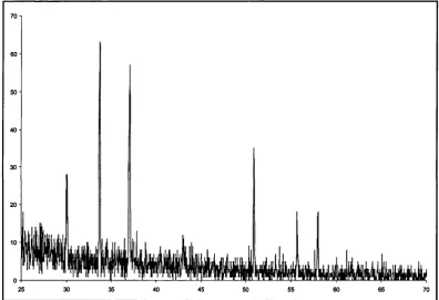
Fig. 2-3 XRD pattern o f AgjSe.
■s 40
2 Theta (degree)
Fig. 2-4 XRD pattern o f AgjS.
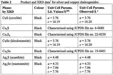
Table 2 Product and XRD c ata* for silver and copper chalcogenides. Phase:
by XRD
Colour Unit Cell Params. Lit. Values/Â^**®^
Unit Cell Params. Observed/A ‘ CuS (covelite) Black a = 3.76
c = 16.19
a = 3.76
c = 16.20
CU2S Black Characterised using JCPDS file no. 6-0680 CU7S4 Black Characterised using JCPDS file no. 22-0250 CuSe (klockmannite) Black a = 3.76
c = 16.19
a = 3.76
c = 16.20
CujSe Black Characterised using JCPDS file no. 19-0401
AgjS (acanthite) Black a = 4.48 a = 4.48
AgjSe (naumannite) Black a = 4.33
b = 7.06 c = 7.76
a = 4.33
b = 7.06 c = 7.76
The reaction o f CuBr withNajE resulted in the formation o f amorphous powders before annealing. ED AX analysis o f the powders gives metal-deficient 1.8:1 copper to sulphur and 1.98:1 selenium atomic ratios. Annealing o f the powders results in the formation o f crystalline Cu^ gS (digenite) and Cuj çgSe (berzelianite) (Fig. 2-5).
90
80
70
S'
c 360
2 50
1
a 40
(0
cs
30
c20
10
0
25
30
35
40
45
2 Theta (degree)
50
55
Fig. 2-5 XRD pattern o f Cu^ ggSe.
2.2.3 Group 12 - Zinc, Cadmium & Mercury:
The reaction o f zinc, cadmium and mercury halides with sodium chalcogenides was performed using the liquid-mediated methatetical route. The reaction schemes are shown in Eqs. 2-9 to 2-11 :
ZnBrj + Na2E
CdClz +
Na^E
HgCl2 + Na2E
ZnE + 2NaBr (E = S,Se) CdE + 2NaCl (E = S,Se) HgE + 2NaCl (E = S,Se)
Eq. 2-9 Eq. 2-10 Eq. 2-11
The reaction o f metal halides with sodium chalcogenides in refluxing toluene for 48 h resulted in these cases in the formation o f crystalline powders in approximately 90% yield. The powders were washed with ethanol and water and analysis o f the water washing showed them to contain sodium halide. Annealing the washed powders resulted in further crystallisation o f the products. Similar to all the reactions so far, the precursors were found not to dissolve in the toluene liquid. Some product data is shown in Table 3.
Table 3 Proc uct and XRD data* for zinc, cadmium and mercury chalcogenides Phase:
by XRD
Colour Unit Cell Params. Lit. Values/Â^^®^
Unit Cell Params. Observed/A *
ZnS Light grey a = 3.76
c = 16.19
a = 3.76
c = 16.20
CdS Yellow a = 4.14
c = 6.72
a = 4.14
c = 6.72 HgS
(metacinnabar)
Black a = 5.85 a = 5.85
HgS (cinnabar)*) Red Characterised using JCPDS file no. 14-1408
ZnSe Light orange a = 3.76
c = 16.19
a = 3.76 c = 16.20
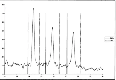
CdSe Deep orange Characterised using JCPDS file no. 8-0459
HgSe Black a = 6.08 a = 6.08
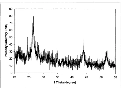
The product o f the reaction o f ZnBr2 with N&2S resulted in a light grey powder which gave an XRD pattern that showed ZnS (sphalerite, zinc blende) (Fig. 2-6). The equivalent selenide reaction gave an orange powder with an amorphous XRD pattern. Annealing at both 250°C and 500°C gave crystalline ZnS and ZnSe. ED AX data for both zinc products gave 1:1 zinc to element atomic ratios.
140
120
à
100
c
3b s 80
2 Theta (degree)
Fig. 2-6 XRD pattern o f ZnS.