IJEDR1401085
International Journal of Engineering Development and Research (www.ijedr.org)479
Modal and Static Analysis of a Standard All-Terrain
Vehicle Chassis
1
Shaik khajamoinuddin,
2B.Balaji
1Post Graduate Student, 2Assistant ProfessorDept. of Mechanical & Production Engg., Sathyabama University, Chennai-600 119
1[email protected], 2[email protected]
________________________________________________________________________________________________________
Abstract - This is a special kind of four-wheeled vehicle used for recreational and exploration purposes. It is designed for
off road usage and for endurance of a rough terrain. In many aspects it is similar to an All-Terrain Vehicle (ATV) except that it is much smaller in size and has safer rollover capabilities. Besides these any successful mini baja vehicle should also be easily transported, easily maintained and fun to drive. Our vehicle can navigate through almost all terrain, which ultimately is the objective behind the making of any all-terrain vehicles. We began the task of designing by conducting extensive research of each main component of the vehicle.
Key words - Static analysis, Modal analysis, Finite element analysis , strength, Suspension.
________________________________________________________________________________________________________ Nomenclature used:
1. FEA – Finite element analysis 2. Lbs - pounds force
3. in: Inches “: Inch 4. LFS: Lower Frame Side 5. Mpa – Mega pascal. 6. Gpa – Giga pascal.
I. INTRODUCTION
The objective of the study is to design and develop the roll cage for All - Terrain Vehicle. Material for the roll cage is selected based on strength, cost and availability. The roll cage is designed to incorporate all the automotive sub-systems. A software model is prepared in Solid works software. Later the design is tested against all modes of failure by conducting various simulations and stress analysis with the aid of Ansys Software. Based on the result obtained from these tests the design is modified accordingly. After successfully designing the roll cage, it is ready for fabricated.
The vehicle is required to have a combination frame and roll cage consisting of steel members. As weight is critical in a vehicle powered by a small engine, a balance must be found between the strength and weight of the design. To best optimize this balance the use of solid modeling and finite element analysis (FEA) software is extremely useful in addition to conventional analysis. The following paper outlines the design and analysis of the chassis design.
There are many ATV’s in the market, but they are not manufactured in India. These ATV’s are assembled here. So we are giving a cost effective design of an All Terrain Vehicle Frame. Since the chassis is the main part of an automotive, it should be strong and light weight. Thus, the chassis design becomes very important. Typical capabilities on basis of which these vehicles are judged are hill climbing, pulling, acceleration and maneuverability on land as well as shallow waters.
This is aimed to design the frame of an ATV which is of minimum possible weight and show that the design is safe, rugged and easy to maneuver. Design is done and carried out linear static analysis and modal analysis for the frame.
II. EXPERIMENTAL DETAILS
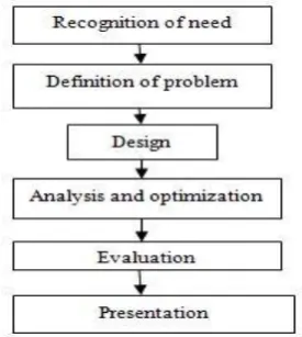
A. Design Methodology
The primary objective of the frame is to provide a 3-dimensional protected space around the driver that will keep the driver safe. Its secondary objectives are to provide reliable mounting locations for components, be appealing, low in cost, and low in weight. These objectives were met by choosing a frame material that has good strength and also weighs less giving us an advantage in weight reduction. A low cost frame was provided through material selection and incorporating more continuous members with bends rather than a collection of members welded together to reduce manufacturing costs. Catia V.0 and SolidWorks 2010 were used to model a frame that is aesthetically appealing and meets all requirements.
B. Problem Definition
The design and development process of the roll cage involves various factors; namely material selection, frame design, cross-section determination and finite element analysis. One of the key design decision of our frame that greatly increases the safety, reliability and performance in any automobile design is material selection. To ensure that the optimal material is chosen, extensive research was carried out and compared with materials from multiple categories. The key categories for comparison were strength, weight, and cost. Here we are going design the chassis for two materials namely AISI Steel 1018 and 4130 Chrome moly steel.
IJEDR1401085
International Journal of Engineering Development and Research (www.ijedr.org)480
Table 1:Material specification chartProperty 1018
1”*0.12”
1020 DOM 1.25”*0.065
4130 1.25”*0.065
Yield strength 365Mpa 539Mpa 670Mpa
Bending stress 2790Nm2 3640Nm2 3640Nm2
Bending strength 391Nm 602Nm 747Nm
Weight 112lbs 82lbs 82lbs
Table 2:Mechanical properties of steel 1018
Properties limits
Density (×1000 kg/m3) 7.7-8.03 Poisson's Ratio 0.27-0.30 Elastic Modulus (GPa) 190-210 Tensile Strength (Mpa) 560.5
Elongation (%) 28.2
Table 3:Chemical properties of 4130 chrome moly steel
Composition Element weight (%)
Carbon (C) 0.28 - 0.33
Chromium (Cr) 0.8 - 1.1
Manganese (Mn) 0.7 - 0.9
Molybdenum (Mb) 0.15 -0.25
Phosphorus (P) 0.035 max
Silicon (Si) 0.15 - 0.35
Sulphur (S) 0.04 max
D. Phases of design
IJEDR1401085
International Journal of Engineering Development and Research (www.ijedr.org)480
Fig.1 3D design of the chassis Fig.2 Mesh model of the chassisE. Finite Element Analysis
After finalizing the frame along with its material and cross section, it is very essential to test the rigidity and strength of the frame under severe conditions. The frame should be able to withstand the impact, torsion, roll over conditions and provide utmost safety to the driver without undergoing much deformation. The solution of a general continuum by the finite element method always follows an orderly step by step process.
Step. 1. Discritization of structural domain Step 2. Selection of a proper interpolation model
Step 3. Derivations of element stiffness matrices (Characteristic matrices) and load vectors. Step4. Assemblage of element equations to obtain the overall equilibrium equation.
Step 5: Solution of system equations to find nodal values of the displacements (field variable) Step 6: Computation of element strains &stresses from the known model displacements
F. Frame Design Static Analysis for AISI steel 1018
IJEDR1401085
International Journal of Engineering Development and Research (www.ijedr.org)481
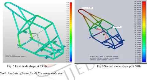
Fig.4 Von misses stress is found to be 48.19MpaFig. 5 First mode shape at 23 Hz Fig.6 Second mode shape plot 50Hz
IJEDR1401085
International Journal of Engineering Development and Research (www.ijedr.org)482
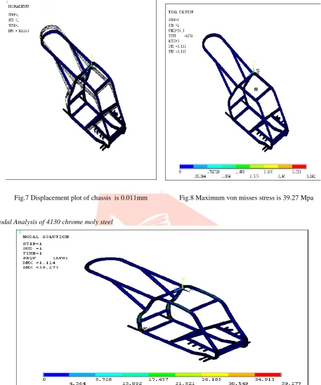
Fig.7 Displacement plot of chassis is 0.011mm Fig.8 Maximum von misses stress is 39.27 MpaH. Modal Analysis of 4130 chrome moly steel
Fig.9 Modal analysis natural frequency is at 56.3Hz
III. RESULTS AND COMPARISION
The theoretical results and the computational results are almost same. The software analysis is done taking into consideration the whole chassis for the applied load, but in the theoretical calculations we consider only the critical clamp to check the stresses induced, hence the theoretical values might differ slightly from the Ansys results. Below is a table comparing the theoretical results and the computational results
Table 4: Obtained Values Comparison
Various stresses Theoritical Results Ansys results for 1018 steel
Maximum Normal stress 40.04Mpa 42.96Mpa
Minimum Normal stress 15.34Mpa 13.04Mpa
IJEDR1401085
International Journal of Engineering Development and Research (www.ijedr.org)483
http://www.mscsoftware.com/support/library/conf/auto00/p02200.pdf[2] Kim, H. S., Hwang, Y. S., Yoon, H. S., Dynamic Stress Analysis of a Bus Systems”, Proceedings of 2nd MSC worldwide automotive conference, MSC, 2000.
http://www.mscsoftware.com/support/library/conf/auto00/p03200.pdf
[3] Fermer, M., McInally, G., Sandin, G., “Fatigue Life Analysis of Volvo S80 Bi-fuel”, Proceedings of 1st MSC worldwide automotive conference, MSC, 1999
http://www.mscsoftware.com/support/library/conf/auto99/p00499.pdf
[4] Johansson, I., and Gustavsson, M., “FE-based Vehicle Analysis of Heavy Trucks Part I” Proceedings of 2nd MSC worldwide automotive conference, MSC, 2000
www.mscsoftware.com/support/library/conf/auto00/p01200.pdf
[5] Oijer, F., “FE-based Vehicle Analysis of Heavy Trucks Part II”, Proceedings of 2nd MSC worldwide automotive conference, MSC, 2000www.mscsoftware.com/support/library/conf/auto00/p01100.pdf
[6] Parnell, T., White, C., and Day, S., “Finite Element Simulation of 1800 Rollover for Heavy Truck Vehicles”, ASCE Engineering mechanics conference, Baltimore, 1999.
http://citeseer.ist.psu.edu/407030.html
[7] Chiba, S., Aoyama K., Yanabu, K., Tachibana, H., Matsuda, K., Uchikura, M., “ Fatigue Strength Prediction of Truck Cab by CAE” , Journal of Mitsubishi Motors TechnicalReview, Vol.15, 2003, pp. 54-60.
http://sciencelinks.jp/j-east/article/200310/000020031003A0250701.php
[8] Lee, D. C., Choi, H. S., Han, C. S., “Design of Automotive Body Structure Using Multicriteria Optimization” , Journal of Structural and Multidisciplinary Optimization, Vol. 32, 2006, pp. 161-167.
http://www.springerlink.com/content/y70812k267632r47/
[9] Jin-yi-min, “Analysis and Evaluation of Minivan Body Structure” , Proceedings of 2nd MSC worldwide automotive conference, MSC, 2000. http://www.mscsoftware.com/support/library/conf/auto00/p00500.pdf