IJEDR1404075
International Journal of Engineering Development and Research (www.ijedr.org)3855
1 M. Tech. Scholar, 2 Assistant Professor, 3 Head of Department
Electronics & Communication Department
Lakshmi Narain College of Technology & Science, Bhopal, (M.P) [India]
________________________________________________________________________________________________________
Abstract - Implementation of digital signal processing (DSP) algorithms in hardware, such as field VLSI, requires a large number of multipliers. Fast, low area multiply-adds have become critical in modern commercial and image DSP applications. A high speed fast Fourier transforms (FFT) and IFFT design by using 8-bit, 16-bit 32-bit and 64-bit algorithm is presented in this paper. My work focus is on two key ideas for improving FFT and IFFT algorithm performance: (1) develop new high performance efficient complex multiplier structure. (2) Parallel processing used in this design. In all algorithms are implemented Xilinx vertex 2 device family and simulated Modalism.
Index Terms - FFT, Ripple Carry Adder, Carry Select Adder, Vedic Multiplier
________________________________________________________________________________________________________
I. INTRODUCTION
Due to the need of high-speed data transmission, today mobile telecommunications industry faces the problem of providing the technology that be able to support a variety of services ranging from voice communication with a bit rate of a few kbps to wireless multimedia in which bit rate up to 2 Mbps. Many systems have been proposed and OFDM system has gained much attention for different reasons. OFDM was first introduced in the 1960s, only in recent years; it has been recognized as an outstanding method for high-speed cellular data communication where its implementation relies on very high-speed digital signal processing. This method has only recently become available with reasonable prices versus performance of hardware implementation.
Since OFDM is carried out in the digital domain, there are several methods to implement the system. One of the methods to implement the system is using ASIC (Application Specific Integrated Circuit). ASICs are the fastest, smallest, and lowest power way to implement OFDM into hardware. The main problem using this method is inflexibility of design process involved and the longer time to market period for the designed chip.
Another method that can be used to implement OFDM is general purpose Microprocessor or Micro Controller. Power PC 7400 and DSP Processor is an example of microprocessor that is capable to implement fast vector operations. This processor is highly programmable and flexible in term of changing the OFDM design into the system.
The disadvantages of using this hardware are, it needs memory and other peripheral chips to support the operation. Besides that, it uses the most power usage and memory space, and would be the slowest in term of time to produce the output compared to other hardware.
The paper is organized as follows: Section II discusses the FFT & IFFT algorithm implementation radix-2 and complex multiplication used inside the butterfly-processing element. Section III shows the proposed three algorithms. Section IV shows the resulting implementation and finally a conclusion is given in section V.
II. FFT & IFFT ALGORITHM
IJEDR1404075
International Journal of Engineering Development and Research (www.ijedr.org)3856
Figure 1: Block Diagram of 8-point FFT AlgorithmIf you have a background in complex mathematics, you can read between the lines to understand the true nature of the algorithm. Don’t worries if the details elude you; few scientists and engineers that use the FFT could write the program from scratch.
IJEDR1404075
International Journal of Engineering Development and Research (www.ijedr.org)3857
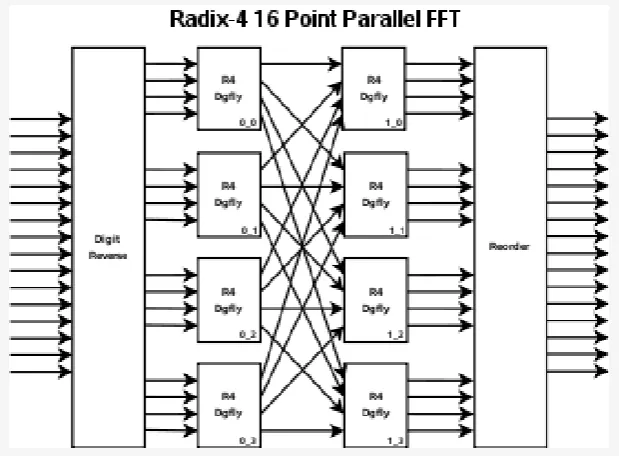
Figure 3: Block Diagram of 32-point FFT AlgorithmThe FFT operates by decomposing an N point time domain signal into N time domain signals each composed of a single point. The second step is to calculate the N frequency spectra corresponding to these N time domain signals. Lastly, the N spectra are synthesized into a single frequency spectrum.
III. PROPOSED ARCHITECTURE
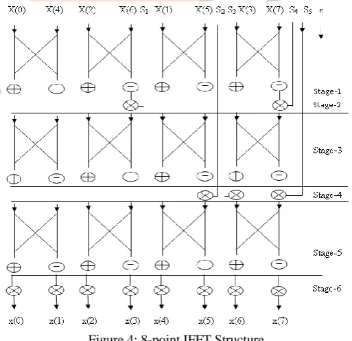
IFFT block is the main block of the proposed design can be divided into 6 stages. IFFT logic diagram is given in figure 4 with all 6 stages. Three main components used in these stages are parallel adder, parallel sub tractor and complex multiplier.
Figure 4: 8-point IFFT Structure
IJEDR1404075
International Journal of Engineering Development and Research (www.ijedr.org)3858
Figure 6: Logic Diagram of Parallel Sub tractorIn figure 6, shown the second component of parallel sub tractor in 6-stage in IFFT algorithm. It is the combination of (n-1) full sub-tractor with one half-sub-tractor. For 8 bit 7 full- sub-tractor and a half sub-tractor is used.
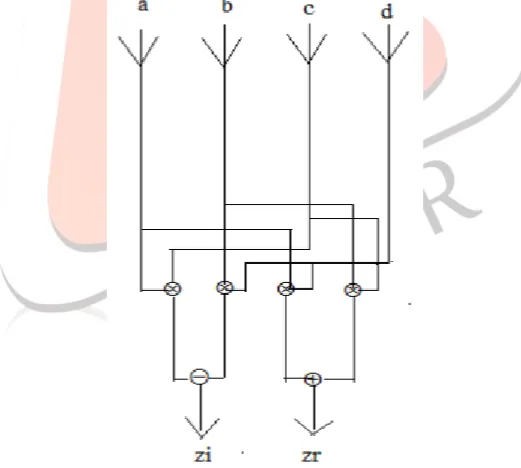
Figure 7: Logic of complex multiplier
In figure 7, shown the third component of complex multiplier in 6-stage in IFFT algorithm. It is used for multiplication of complex numbers such as A + JB with C + JD. After multiplication output comes in a form of (AC – BD) +J (AD + BC) component of complex multiplier are parallel-adder, parallel sub-tractor and multiplier.
IV. SIMULATION RESULT
IJEDR1404075
International Journal of Engineering Development and Research (www.ijedr.org)3859
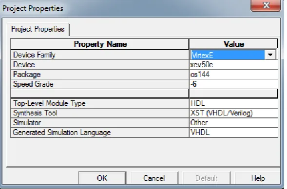
Implementing the all the stage up to six stages has been captured by VHDL and the functionality is verified by RTL and gate level simulation. To estimate the timing, area and power information for ASIC design, we have used Synopsys Design Compiler to synthesize the design into gate level.Table1: Synthesized Results for stage up to six levels in IFFT.
Number of slice Number of Slice Flip Flops Number of 4 input LUTs Required time after clock (nsec)
Stage-I 116 203 256 10.752
Stage-II 101 177 256 13.991
Stage-III 195 342 256 19.382
Stage-IV 217 381 247 21.940
Stage-V 289 506 247 27.825
Stage-VI 356 621 192 49.528
0 1000 2000 3000 4000 5000 6000 7000 8000 9000
Sice FF LUTs MCPD
8-point 16-point 32-point 64-point
Figure 8: Chart diagram of 8-point, 16-point, 32-point and 64-point FFT and IFFT MCPD: Maximum Combinational path Delay
Slice: Number of Slice FF: Number of Slice Flip Flop LUTs: 4-input LUTs
V. CONCLUSION
FFT and IFFT algorithm is successfully developed using VHDL software. The output from each module was tested using appropriate software to ensure the correctness of the output result. This is to ensure that the hardware module was correctly working when implemented in the FPGA hardware. During the implementation stage, the operation for IFFT is tested using Xilinx software.
REFERENCES
[1] Charles. Roth Jr., “Digital Systems Design using VHDL”,Thomson Brooks/Cole, 7th reprint, 2005.