Patch Antenna Parameters Variation with
Ground Plane Dimensions
G.V.P.Pranathi1, Dr.N.Deepika Rani2, Dr.M.Satyanarayana3, Prof.G.T.Rao4
PG Student, ECE, G.V.P. College of Engineering (Autonomous), Visakhapatnam, India1 Associate Professor, ECE, G.V.P. College of Engineering (Autonomous), Visakhapatnam, India2 Associate Professor, ECE, M.V.G.R College of Engineering (Autonomous), Vizianagaram, India3
Professor, ECE, G.V.P. College of Engineering (Autonomous), Visakhapatnam, India 4
ABSTRACT: An inset fed rectangular patch antenna is designed to operate at 2.4 GHz using an FR-4 substrate of height h=1.6mm. Initially the ground plane dimensions are kept as 6h+L and 6h+W (short edge) ; Where L is length of patch and W is width of patch. It is found to have a low gain. To improve the gain, ground plane dimensions length and width are varied in multiples of Length (L) and Width (W) respectively. For double ground (2L, 2W) case, a gain of 2.6494dB is observed. A further improved gain of 3.0524dB is achieved by using triple ground (3L, 3W).The other parameters like VSWR, Return Loss and directivity are also improved by increasing ground plane dimensions .The antennae are fabricated and tested using VNA E5071C.
KEYWORDS: Gain, Return Loss, VSWR and Directivity.
I.INTRODUCTION
Patch antennas have become popular in the recent days due to various advantages like their low profile, low cost, compatibility with IC technology and conformability with any shaped surface [1]. Recent technology advancements necessitate antenna design to wide band performance.
Patch antennas come in different shapes, but most commonly used shapes are rectangular and circular. The dimensions of patch antenna depend on the operating frequency and the dielectric constant of the substrate. The higher the operating frequency, the lower is the size of the patch [3].
The paper focuses on design, simulation, fabrication and analysis of a patch antenna operating at 2.4GHz with varying ground plane dimensions. It is observed that increased dimensions of ground plane increases the gain of the antenna. Other parameters measured are Return Loss and VSWR.
II. ANTENNA DESIGN
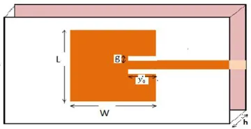
Configuration of the patch antenna is shown in Figure 1
Figure 1: Geometry of the patch antenna
Vol. 4, Issue 8, August 2015
Step 1: Selection of , ,ℎ :
Resonant frequency selected( ) :2.4GHz
Dielectric constant( ) :4.4
Height(ℎ) :1.6mm Step 2: Calculation of Width ( ):
=
2 ( + 1/2
Where = 3*108m/s
Step 3: Calculation of Actual Length (L):
The effective length of patch antenna depends on the resonant frequency ( ).
= 2
Where = + 1 + 12
The effective length of patch antenna is equal to the one half of a wave length within the dielectric medium.
The E-fields at the edges of the patch undergo fringing effects. Because of these effects, effective length of the patch antenna appears to be greater than its actual length. So, actual length of the patch antenna is usually considered as
< 2 .
Actual length and effective length of a patch antenna can be related as
= −2∆
Where ∆ is a function of effective dielectric constant and the width to height ratio .
Δ
ℎ = 0.412
( + 0.3) ℎ + 0.264
( −0.258) ℎ + 0.8
Step 4: Calculation of Inset feed Depth ( ):
The edge of the patch antenna will have high input impedance. Impedance falls rapidly if the inset position is moved from edge of the patch towards the centre .For providing impedance matching with a 50Ωconnector, a curve fit formula for the inset feed depth is expressed as [2]
= 10 {0.016922 + 0.13761 −6.1783 + 93.187 −682.69 + 2.561.9 −4043 + 6697}
2
Step 5: Calculation of feed width ( ):
ℎ =
⎩ ⎪ ⎨ ⎪
⎧ 8
−2 ℎ ≤2
2
−1−ln(2 −1) + −1
2 ln( −1) + 0.39−
0.61
ℎ ≥2
.Where = + 0.23 + . =
√
Step 6: Calculation of notch gap ( ):
Resonant frequency of patch antenna depends on the notch gap ( ).Expression which relates notch gap and resonant frequency is given by [5]
=
2∗
4.65∗10
( )
With the help of above equations the dimensions of the patch are calculated and shown in Table I.
TABLE I Dimensions of the patch antenna
III.RESULTSANDDISCUSSION
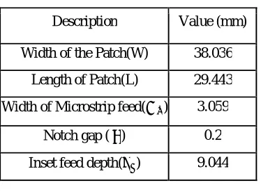
By considering the ground plane dimensions i.e., Length and Width of substrate as 6h+L and 6h+W (short edge), along with the dimensions in Table Ia patch antenna is drawn. It is simulated using HFSS 13.0and fabricated by thermo lithography. Patch is tested using VNA E5071C.It is found that the patch resonates at 2.35GHz with reflection co-efficient -10.2411dB. At 2.4GHz, Reflection co-co-efficient observed is-5.8404 dB. From this it is observed that frequency of resonance is at 2.35GHz instead of 2.4GHz. To achieve the frequency of resonance at 2.4GHz,only notch gap is varied and all other dimensions are kept constant. At notch gap=0.6mm, reflection co-efficient observed is-8.6242dB at 2.4 GHz.
Generally for antenna to radiate efficiently reflection co-efficient should be less than -9.5424dB. To improve the reflection co-efficient, length of the patch is varied by keeping notch gap (g) =0.6mm. Now the dimensions of the inset fed short edge patch antenna are considered as in Table II to resonate at 2.4GHz.Figure 2(a) shows the top view of the patch and Figure 2(b) shows the bottom view of the patch.Simulated reflection co-efficient curve ( ) and VSWR for the inset fed short edge patch antenna in HFSS 13.0 is shown in Figure 3 and Figure 4 respectively.
Description Value (mm)
Width of the Patch(W) 38.036 Length of Patch(L) 29.443 Width of Microstrip feed( ) 3.059
Vol. 4, Issue 8, August 2015
TABLE II Dimensions of the inset fed short edge patch antenna
Figure 2(a): Top view of an inset fed short edge patch antenna
Figure 2(b): Bottom view of an inset fed short edge patchantenna
Figure 3: Reflection co efficient ( ) Curve for inset fed short edge patch antenna with ground plane dimensions 6h+L and 6h+W
1.00 1.25 1.50 1.75 2.00 2.25 2.50 2.75 3.00
Freq [GHz] -14.00 -12.00 -10.00 -8.00 -6.00 -4.00 -2.00 0.00 d B (S t( R e c ta n g le 2 _ T 1 ,R e c ta n g le 2 _ T 1 )) HFSSDesign1
XY Plot 2 ANSOFT
m1
Curve Info dB(St(Rectangle2_T1,Rectangle2_T1)) Setup1 : Sw eep
Name X Y
m1 2.4000 -13.1508
Description Value (mm)
Width of the Patch(W) 38.036 Length of Patch(L) 28.9 Width of Microstrip feed( ) 3.059
Figure 4: VSWR Curve for inset fed short edge patch antenna with ground plane dimensions 6h+L and 6h+W
From Figure 3 and Figure 4 it is observed that reflection co-efficient ( )and VSWR are -13.1508 dB, 1.5642 respectively at 2.4GHz
By considering the above dimensions in Table II the patch is fabricated and tested by using VNA E5071C. Fabricated patch is shown in Figure 5.
Figure 5: Fabricated inset fed short edge patch antenna with ground plane dimensions 6h+L and 6h+W
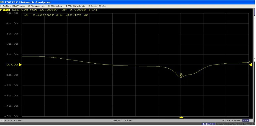
The reflection co-efficient for the Inset fed short edge patch is shown in Figure 6 and Figure 7 shows the VSWR curve of the fabricated inset fed patch antenna.
Figure 6: Reflection co efficient ( )curve of the fabricated inset fed short edge patch antenna with ground plane dimensions 6h+L and 6h+W
1.00 1.25 1.50 1.75 2.00 2.25 2.50 2.75 3.00
Freq [GHz] 0.00
50.00 100.00 150.00 200.00 250.00 300.00
V
S
W
R
t(
R
e
c
ta
n
g
le
2
_
T
1
)
HFSSDesign1
XY Plot 3 ANSOFT
m1
Curve Inf o V SWRt(Rectangle2_T1) Setup1 : Sw eep Name X Y
Vol. 4, Issue 8, August 2015
Figure7: VSWR curve of the fabricated inset fed short edge patch antenna with ground plane dimensions 6h+L and 6h+W
From Figure 6 and 7 the reflection co efficient ( )and VSWR of the fabricated inset fed Short edge patch antenna are observed as-12.172dBand 1.6233respectively at 2.4053367GHz
Gain of an inset fed short edge patch antenna is shown in Figure 8.
To improve the gain, ground plane dimensions are varied as doubleground (2L, 2W) and triple ground (3L, 3W).Along with gain other parameters Reflection coefficient, VSWR and directivity are observed. The simulated results using HFSS 13.0 and the measured values using VNA E5071C are kept in Table III.
TABLEIII COMPARISON OF PARAMETERS FOR GROUND PLANE VARIATIONS
VI.CONCLUSION
By varying ground plane dimensions from short edge (6h+L, 6h+w) to triple ground (3L, 3W) there is an improvement in Return Loss from -13.15 dB to -20.2146 dB at 2.4 GHz and also a gain improvement from 1.5948dB to 3.0524dB is observed. This confirms that the design of ground plane with suitable dimensions along with the patch design is important for optimization of parameters.
REFERENCES
[1] C. A. Balanis, “Antenna Theory, Analysis and Design,” John Wiley & Sons, New York, 1997
[2] M.Ramesh, “Design Formula for Inset Fed Microstrip Patch Antenna’’,Journal of Microwave and Optoelectronics,Vol 3,N.o 3, December 2003.
[3] Y T Lo and S W Lee, editors, “Antenna Handbook Theory, Applications & Design’’, Van Nostrand Rein Company, NY, 1988.
[4] M A Matin, A. I. Sayeed, “A Design Rule for Inset-fed Rectangular Microstrip Patch Antenna’’, WSEAS Transactionson Communications, Issue 1, Volume 9, January 2010
Ground plane dimensio
-ns
Resonant Frequency
in GHz
Reflection coefficient (S11)
in dB
VSWR Gain
in dB
Directi vity in dB
Simulated Measured Simulated Measured Simulated Measured Simulated Simulated Short
Edge (6h+L, 6h+w)
2.4 2.405336 -13.1508 -12.172 1.5642 1.6233 1.5948 4.8816
Double Ground (2L,2W)
2.4 2.407878 -18.5306 -19.750 1.2162 1.2344 2.6495 5.7486
Triple Ground (3L,3W)