Numerical simulation of axisymmetric valve operation for
different outer cone angle
Emil Smyk*
UTP University of Science and Technology, Faculty of Mechanical Engineering, Control Group, Poland
Abstract. One of the method of flow separation control is application of axisymmetric valve. It is composed of nozzle with core. Normally the main flow is attached to inner cone and flow by preferential collector to primary flow pipe. If through control nozzle starts flow jet (control jet) the main flow is switched to annular secondary collector. In both situation the main flow is deflected to inner or outer cone (placed at the outlet of the valve's nozzle) by Coanda effect. The paper deals with the numerical simulation of this axisymetric annular nozzle with integrated synthetic jet actuator. The aim of the work is influence examination of outer cone angle on deflection on main stream.
1 Introductions
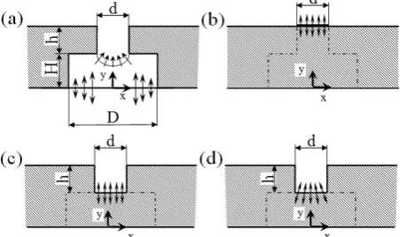
One of the method of flow separation control is application of axisymmetric valve. The valve of this type was described first time in 2010 [1] and its operation is described precisely in [2, 3]. Exemplary application of axisymmetric valve is presented in fig.1.
Axisymmetric valve is composed from nozzle with core. Normally the main flow is attached to inner cone (fig. 2) and flows by preferential collector to primary flow pipe. If through control nozzle flows jet (control jet), the main flow is switched to annular secondary collector. In both situation the main flow is deflected to inner or outer cone (placed at the outlet of the nozzle, fig.2) through Coanda effect. Generally as control jet is used synthetic jet generated by actuator embedded in the core of nozzle [1, 2, 3].
This type of valve uses two phenomena – Coanda effect and synthetic jet. Both of phenomena have influence on main flow switching and they cooperate in this process. Synthetic jet (control jet) detaches the main flow from inner cone and the main flow additionally is deflected by outer cone (Coanda effect). Only the occurrence of these two phenomena redirects the main flow.
1.1 Synthetic jet
Synthetic jets are generated by periodically ingestion and expulsion of fluid at the exit of a nozzle or across orifice [4]. Because is no net flux of fluid during one full cycle of operation, synthetic jet is named zero– net mass– flux (ZNMF) jet. At some distance from exit of nozzle are created edge vortices. The idea of synthetic jet generation is presented in fig. 3.
Fig. 1. Example application of axisymetric nozzle with synthetic jet actuator – from [2]
Fig. 3. Idea of the synthetic jet formation, 1– moving diaphragm, 2– nozzle, 3– edge vortices
Synthetic jet has many applications: in aviation, aeronautics, refrigeration systems and active flow control etc. One of synthetic jet applications examples is axisymmetric nozzle presented in this paper.
1.2 Coanda effect
Jets have tendency to adhesion and to flow nearby solid boundaries. This phenomena is known as Coanda effect. Flows deflected by a curved surface are used in many applications [5, 6]. Coanda effect is still not exactly known, as evidenced by the extensive investigation [7]. The reason for this state of affairs is a high level of complexity this phenomena. The Coanda effect depends on parameters such as: roughness and temperature of the solid surface, temperature, viscosity, density of fluid end other. Exact influence of these parameters on Coanda effect is still under investigation [8].
Fluids deflected by the surface adhesion force. If this force is predominant then fluid follows along the surface. This phenomena and Coanda effect is used to active flow control in axisymmetric value [1, 2, 3] (fig.1).
The Canada effect is very important for the proper operation of the axisymmetric valve. It affects the behaviour of the stream and it can determine on the correct valve operation. One of the element which has important influence on Coanda effect is outer cone angle (fig.2) and this issue is the topic of this paper.
This investigation presents numerical simulation of axisymetric nozzle (used to valve construction) and the influence of the outer cone angle on behaviour of main flow.
2.Numerical investigation
2.1. Simulation of synthetic jet
Main problem of numerical investigation of axisymmetric valve is simulation of synthetic jet. Recently, numerical research of synthetic jet was conducted in many publications [9-14]. Deserves special attention [10], in which was presented four different methods of synthetic jet simulation. Fig. 4 shows variants of synthetic jet models.
Fig. 4a shows typical method of synthetic jet simulation. In this solution, moving diaphragm
of synthetic jet actuator is simulated by sinusoidal velocity profile. The velocity (normal to the wall) is defined as:
, 0, 0sin
v x y t v f x Zt (1) Where t is time, v0 is amplitude of velocity, is angular frequency. Three different spatial distribution function f(x) were considered:
1
2 1
1
sin( )
sin ( )
f x x d
x d
S
S
° ® ° ¯ (2)Such a simple boundary conditions representation eliminates the need to simulate of the diaphragm.
Fig. 4. Schema of different method on synthetic jet simulation (a)typical solution – SJ slot for a full cavity configuration, (b) the modified boundary conditions, (c) and (d) slot-only models
The easiest model of synthetic jet simulation is shown in fig. 4b. In this case the chamber and nozzle of actuator are omitted and only nozzle exit is taken into account. It is inaccurate but uncomplicated model. The intermediate solution is simulation of all nozzle (fig. 4c, d), so called slot-only actuator model [10]. The sinusoidal velocity can be defined as parallel to the axis of the nozzle (fig. 4c) or depend on distance from the axis (fig. 4d). The detailed discussion of presented models and their comparison was conducted in [10]
Due to the complexity of the analyzed object (fig. 2) was decided to use slot-only model with velocity normal to boundary. The velocity was defined as:
0sin
v t v Zt (3)
2.2 Model geometry and mesh
As mentioned this investigation shows how the outer cone angle affect on behaviour of main flow. Therefore, it was prepared different models of axisymmetric valve with different cone angle. Example model with basics dimensions is presented in fig. 5. The value of investigated outer cone angle was presented in table 1.
As mentioned the synthetic jet actuator was replaced by slot–only model (see fig. 4b).
Fig. 5. Model of axisymmetric valve – front view, for = 40°
Computational meshes for each model was generated in ANSYS Meshing. For each model was defined the same face sizing for the same walls. The difference of nodes and elements numbers is caused by different outer cone angle. The element quantity was very similar for each case. Example element quantity was shown in fig. 6. The models exploit tetrahedron meshes (Tet4).
Table 1. Models parameters
Outer cone angle
Į Number of nodes Number of elements
90° 580 605 3 023 419
80° 388 676 1 993 636
70° 385 616 1 977 427
60° 381 609 1 956 745
50° 378 915 1 942 058
40° 373 193 1 911 981
30° 366 726 1 877 306
20° 356 014 1 819 285
10° 329 108 1 682 436
2.3. Boundary conditions
Boundary conditions are shown in fig. 6. It must be noted, that all unlabelled surfaces belong to the Walls group, and they was omitted to preserve legibility of figure. On this surfaces, the boundary condition "wall" was applied. Velocity in nozzle of synthetic jet actuators was modelled by UDF (user defined function), which is defined as dependency of velocity on time. All boundary conditions are described in table 2.
Fig. 6. Boundary conditions used in numerical modelling
Table 2. Boundary conditions
Label Boundary
condition type Parameters, description
Inlet mass – flow – inlet
Inlet mass flow: 5,78 · 10-3 kg/s, or
2,835 · 10-3 kg/s Outlet pressure – outlet Determined model
boundary, outlet SJ nozzle velocity – inlet Velocity profile defined
by UDF
Symmetry symmetry Symmetry plane
Walls Wall Walls of nozzle and outer cone
It must be noted that inlet was defined as "mass– flow– inlet" with two values. To verify the accuracy of the simulation were compared the simulation results with results presented in [3]. Accordingly, the inlet parameters was used such as in [3] (2,835 · 10-3 kg/s, it is mass flow rate for half of valve). In case of main simulation was used twice as much mass flow rate (5,78 · 10-3 kg/s).
2.4. Simulation parameters
Numerical simulation was done in ANSYS Fluent 16. It was used simulation without gravity with standard k- viscous model with enhanced wall treatment, and with automatic model constants. It was used SIMPLE solution method and standard solution initialization. The need of synthetic jet simulation in simulation resulted in the use of transient model with time step equal 1/20 of velocity v(t) period (T= 2/Z, see formula (3)).
3. Simulation
3.1 Simulation model verification
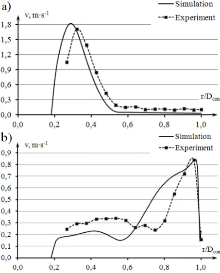
The first step of test was comparison of velocity profile measured on the real object with results of simulation. The purpose of this comparison is verification of simulation model. The verification was carried out for outer cone angle = 30°, and the velocity profile was measured in the plane of the stream outlet from the outer cone (slot between inner cone and the outer cone ending). The experimental and simulation results are presented in fig. 7.
In fig. 7a was shows comparison of experimental and simulation velocity profile received for a model/test stand without synthetic jet. The main stream deflects to the inner cone by a Coanda effect. Therefore, the velocity near the inner cone is noticeably higher. The difference between simulation and experimental data is slight and velocity profile shift can be due by probe positioning errors. Experiment and simulation are compatible.
Fig. 7b shows velocity profile comparison with activated synthetic jet. The main stream is pushed back toward the outer cone and deflects to it and thus the velocity is higher near the outer cone. In experiment stream is more condensed (near the outer cone) than in simulation. However, this discrepancy is probably case not an accurate the synthetic jet representation in simulation (inaccurate definition of UDF).
Because, the difference between simulation and experimental data was inconsiderable, it was decided that selected simulation model was chosen correctly.
3.2. Influence of outer cone angle on stream
In fig. 8 was presented contours of velocity. These pictures shows calculated flow field on symmetry. The detachment of the stream (to inner cone) appears with outer cone angle equal 30° or less. It should pay attention in fig. 8f ( = 40°). In this case stream returns in the direction of outer cone. This effect is probably caused by the formation of a vacuum between the stream and outer cone.
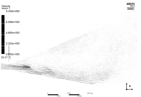
The stream attachment to the outer cone takes place only for = 30° or less. In these cases the stream returns in the direction of inner cone, but initially it is concentrated close to the outer cone wall. The reason for this is a vortex formed between the flowing stream and the inner cone (fig. 9). The vortex causes the stream return to the inner cone. However, it probably helps to leads of stream to outer cone, near the annular gap. It must be noted that the existence of vortex has two consequence. Initially it detaches the stream from the inner cone and then it deflects the main stream towards the inner cone.
Fig. 9. Velocity vectors between inner and outer cone on symmetry plane for = 10°
4. Conclusion
In paper was done the simulation of axisymetric annular nozzle for different outer cone angle . It has been demonstrated that for the selected simulation model the numerical data are compared with experimental data. The diminution of the outer cone angle has a positive effect on the stream redirection. Additionally has been shown the existence of vortices, which has considerable influence on the main stream.
The next step of research should be a investigate the influence of partition (splitter), between inner and outer cone, on the stream. More attention must be devoted to velocity vectors, and SJ boundary conditions.
Acknowledgements
Scientific work financed from the budget for science in the years 2015/2018 as a research project within the program under the name "Diamond Grant ".
References
1. V. Tesa, Z. Trávníek, ZpĤsob dvourežimového Ĝízení prĤtoku tekutiny a zaĜízeník provádČní tohoto zpĤsobu (Ways and means for two-regime control of fluid flow; in Czech), Czech Republic Patent Document Nr. 303280, DOI: 10.13140/ 2.1.4160.8963 filed 30th Jul 2010
2. T. Václav, Z. Brouková, J. Kordik, Z. Trávníek, K. Peszyski, Valves with flow control by synthetic jets, EPJ Web of Conf. 25, EDP Sciences (2012) 3. V. Tesa, M. Pavelka, E. Smyk, K. Peszyski,
Control of flow separation by vestigial" synthetic jet, Colloq. Fluid Dyn. (2014)
4. B.L. Smith, A. Gezler, The formtion and evaluation of synthetic jets, Physic of Fluids 31, p. 2281 (1998) 5. F. Lalli, A. Bruschi, R. Lama, L. Liberti,
S. Mandrone, V. Pesarino, Coanda effect in coastal flows, Coastal Engineering 57(3), pp.278-289 (2010)
Exp. Therm. and Fluid Science 33.4, pp.675-682 (2009)
7. A. Dumitrache, F. Frunzulica, T. C. Ionescu, Mathematical modelling and numerical investigations on the Coanda effect, INTECH Open Access Publisher (2012)
8. A. Dumas, M. Subhash, M. Trancossi, J.P. Marques, The influence of surface temperature on Coanda effect, Energy Procedia 45, 626-634 (2014)
9. T. Hyhlík, Z. Travnicek, F. Marsik, Numerical simulation of a synthetic jet into quiescent air, ISTP-16 (2005)
10. R. Raju, E. Aram, R. Mittal, L. Cattafesta, Simple models of zero-net mass-flux jets for flow control simulation, International Journal of Flow Control 1(3) (2009)
11. V. Dvoák, P. Danová, P. Švarc, Experimental investigation into flow in an ejector with four synthetic jets, EPJ Web of Conf. 25, EDP Sciences (2012)
12. Z. Trávniek, P. Danová, J.H. Lam, V. Timchenko, J. Reizes, Numerical and experimental studies of a channel flow with multiple circular synthetic jet, EPJ Web of Conf. 25, EDP Sciences (2012)
13. A.C. Macovei, F. Frunzulica, Numerical simulations of synthetic jets in aerodynamic applications, INCAS Bulletin 6(1) (2014)
![Fig. 1. Example application of axisymetric nozzle with synthetic jet actuator – from [2]](https://thumb-us.123doks.com/thumbv2/123dok_us/8142646.1357294/1.595.310.540.357.505/fig-example-application-axisymetric-nozzle-synthetic-jet-actuator.webp)