National Research Tomsk Polytechnic University, Lenin Avenue, 30, 634050 Tomsk, Russia
Abstract. Peculiarities of separation processes in cyclone battery separators have been considered on liquid and solid disperse phases. The difference in efficiency between individual and battery liquid separators is slight .Concentration of disperse liquid phase in refined gases is 0.1–0.3 kg/kg. In operating on dry gases with abundance of dust the separation condition changes due to peculiarities of disperse phase behavior from solid particles .Flow parameter assessments in cyclones by different correlation of flow areas at the input and output have been conducted. Differences of flow parameters in conical and cylindrical cyclones have been explored. The analysis and causes of unsatisfied work of industrial battery separator with cyclone elements have been carried out.
Battery devices with cyclone elements are extensively used in oil and gas industry for extraction of liquid and solid impurities from natural and petroleum gas [1]. There are a lot of different battery separators, characterized by geometric correlations of cyclone elements, their arrangements, elements of flow stabilization, acquisition of disperse phase from the flow and refined gas. In most cases these separators operate on gas-liquid flow. The concentration of disperse phase in refined gases is within the acceptable limit in this case. In operating of these separators on dry gases with abundance of dust the situation changes due to peculiarities of disperse phase behavior from solid particles.
The comparison of cylindrical and conical cyclones
The main geometrical correlations that affect the efficiency and hydraulic resistance are relations of inlet pup-joint area to cyclone planned area, the relation of inlet pup-joint area to gas outlet pup-joint area, the relation of dust outlet to outlet pup-joint area, cyclone cone angle [2].
One can have an idea of flow characteristics in cyclones with different geometry using data [2,3], where there are distributions of flow velocity fields in the volumes of conical and cylindrical cyclones. The distribution of circular velocity moments, but not the very velocities, is presented in [2]. As a matter of fact, the scale for moments relates to circular velocities that is easy checked up by gas balance consumption at the separator inlet and outlet. Typical flow lines have been given in cyclones [2, 3]. Given data [2,3] have been used for determinationsnmi andnRifrom correlations
Vi/VR=(R/ri)nRi; Vi/VCi=(rCi/ri)nmi, (1)
aCorresponding author:[email protected]
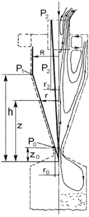
Figure 1. Scheme of gas flow lines in cross-current high-efficiency conical cyclone.
whereVi,VR,Vci – circular gas velocities on the fixed radius in sectioni, on the maximum radiusR, on the surface radius in sectioni,ri,R,rci – corresponding radii (wall thickness zone is negligible). A radius has been taken as a fixed one, whereVi =Vmax. The values of relative mass flow in downward movement have been calculated by the formula
GH i=
2
rci
rwoi
wirdr
/VRFBX, (2)
wherewi – value of axial velocity on a radiusri;rci,rwoi – surface radii and zero axial velocity on the
periphery of sectioni.
Experimental data show [4], that for cyclones Finlet/Foutlet<1 valuenmi andnRi differ more by removal of gas outlet pipe out of inlet section. The alteration character for cylindrical and conical cyclones is opposite: in conical nmi < nRi it decreases, in cylindrical nmi < nRi it increases when approaching the cyclone bottom. The downward flow has value less than 10% from basic data in the dust outlet of conical cyclone separator, while in cylindrical one more than 50% withFinlet/Foutlet=0.29. Increase ofnmcorresponds to increase of radial flow velocity. Centripetal acceleration is implemented in the dust outlet of conical cyclone separator that is 30 times as much than in cylindrical cyclone.
With increase of particle concentration the level of tangential velocity decreases. It is typical for conical part of cyclone [4]. It leads to pressure fall alteration (mainly along the height of conical part) depending on alteration of particle concentration in the inlet flow.
Figure1shows a scheme of high-efficiency conical separator with individual dust–collecting bag. On the right, there are lines of gas flow, on the left there are estimated and basic values, corresponding to hypothetical gas flow line in a cone.
If velocity gradients are small, radial pressure distributions in every section of cyclone are determined with formula
Or in dimensionless form
dP /dz=2/z, P=P/V2
R,=/VR,z=z/ h,
whereh–cone height with a surface, formed by a complex of marked flow lines (pic.1). Ifi/VR=(R/ri)nRi, then for marked flow line is
/VR =(h/z)n, =z−n. (6) For conical cyclone (Fig.1)nRchanges in range 0.47–0.35. The average value isn=0.41.
In the upper part of cyclone the nature of circle velocity distribution doesn’t change with concentration alteration, although levels of these velocities decreases in a way by high concentrations [4]. In the lower part of cyclone, mainly near dust outlet, the value of circle velocities decreases. So, a sign n in formula (4) depends on particle concentration in the flow and may be approximated by
n=n0(1−ncn),
where n0–index of power in Eq. (4) with c=0, where c–particle concentration in the flow at the cyclone inlet, kg dust/kg air, n,n–coefficient and index of power, that depend on type of cyclone, physicochemical properties and dust dispersion. Value ofnfor cyclone is shown in Fig.1and is in the range from – 1.00 to 0.41.
For marked flow line the pressure falls in the upper part along the radius and cyclone height are written as :
P1−2=P1−P2=
r2−2nR −1 2nR
P1−0= z0 −2n
−1
2n , npu n=0 P1−0= −lnz0, npun=0.
(7) Approximate values ofncan be obtained, by measuring pressure falls among flows in the inlet pup-joint and dust – collecting bag, using formula (7).
For instance, for dust-free flownR =0.41,P1−2=1.97,P1−0=5.28,n=nR =0.41; for dusty flow nR =0.41, P1−2 =1.97, P1−0 =0.99, n= −0.5. That is by increasing of concentration the pressure fall in cyclone along the height decreases, but pressure near dust outlet increases.
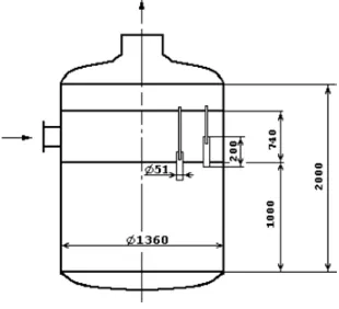
Figure 2. Scheme of industrial separator.
Table 1. Arrangement of elements in industrial separator.
rcle diameter, 1240 1110 980 850 720 590 460 330
2r,mm
Number of 52 45 40 36 30 23 18 11
elements, n,
Coarse particles near dust outlet are more subjected to braking effect of the surface, and are harder transported by flow, and under concentration more than 10 gr/M3are accumulated in the cyclone volume due to poor outflow of particles. In this case forced vortex isn’t formed in the collecting bag ,but in the separation zone in the cyclone volume on the rotary layer of particles. It causes higher coarse particle carry-over from the separator [6].
Operation of parallel cyclones
Industrial separator consists of three one above the other sections: impurity gathering section, gas inlet section and section of inlet and outlet refined gas. Cyclone elements are cylindrical cyclones with case diameter 57×3.5 mm, height 190 mm, outlet pipe diameter 35×2.5 mm and a blade that consists of three vanes with quarter turn bend off-axis. Outlet pipe in the inlet part has a confuser, so a gap between a case and an edge is 4.5 mm, outlet slope angle from a blade is=50◦. All cyclone vanes have similar clockwise direction of swirl. Cone part of the case has a height of 40 mm, discharge hole diameter is 25 mm.
The element refers to medium-efficiency with low coefficient of flow twist. The number of elements, depending on circle diameter are in Table1.
Cyclone elements are absent on the part of gas inlet in the sector. Peripheral cyclone elements are case element higher.
Gas enters into distribution chamber through cyclones and central tubes being refined and goes out into collection chamber. Gas scrubber efficiency by this arranging was unsatisfactory.
and in the dust collecting space it flew into cyclones located on the smaller radii.
Conclusion
Technical solutions that provide stable process of dust separation and gas cleaning have been given in this project. Solutions for hydraulic stability of elements’ improvement by dust removal channels have been developed.
This work was supported by as part of the program to improve the competitiveness of the National Research Tomsk Polytechnic University.
References
[1] A. Bukin, V. Panin, C. Vlasov. Development and experience operation of process equipment for gas transportation of Achimov horizons. Gas Industry, No. 11, p. 23–26 (2011)
[2] J. Smith. Experimental study of a whirl in cyclone separator. American Society of Mechanical Engineers. Technical Mechanics. V.84. No. 4, p. 229–236 (1962)
[3] V. Straus. Industrial gas treatment: Translated from English. Moscow: Khimiya, 616 (1981) [4] M. Vasilevskiy, E. Zykov, B. Loginov. Gas cleaning stability in cyclone dust chamber RAS
(Russian Academy of Science). Energetica, No. 5. p.113–124 (2005)
[5] P. Kouzov, A. Malgin, G. Skrjabin. Gas and air dust cleaning in chemical industry. Leningrad: Khimia. 256 (1982)