ISSN 2348 – 7968
Design and Development of a Security Surveillance System based on
Wireless Sensor Network
Arulogun, O. T.
1, Adigun, A. A
2,
Okediran O. O
3and Ganiyu, R. A
41,2,3,4
Department of Computer Science and Engineering, Ladoke Akintola University of Technology, Ogbomoso, Oyo State, Nigeria {otarulogun, aaadigun,oookediran, raganiyu}@lautech.edu.ng
Abstract
In this paper, we design and develop a real test bed platform based on wireless sensor network (WSN) integrated with camera sensors for security surveillance, identification and classification of known and unknown objects in the community. Two categories of camera sensor nodes were integrated: fixed camera nodes and mobile camera nodes, were deployed in wireless mesh network topology using Mikrotik HWMP+ routing algorithm. Data gathering were performed by the camera sensor nodes and sent to the appropriate base station (BS) where data analysis are done to extract useful information from the sensed data. Various techniques and know-how to fulfill and implement a WSN-based integrated visual surveillance system were highlighted
.
Keywords: Wireless sensor networks, camera sensor networks, security surveillance, testbeds, mesh network
.
1. Introduction
Wireless sensor network is a promising and evolving sensor based monitoring technology that is playing a tremendous role in the future of computing for development worldwide; due to its promising wide application areas and potential enabler for Internet of things paradigm [2]. Sensor based monitoring is the passive or active collection of physical and environmental data of geographical area of interest such as light, temperature, humidity, dust particles, pressure, noise level, audio, video, carbon dioxide level, soil moisture content, carbon dioxide level, oxygen level, blood pressure, enzymes, etc. into secured database for the purposes of trend analysis, prediction, recommendation to the authorities and the general public as may be appropriate using smart wireless sensor devices. A collection of self-organized wireless sensor devices called sensor nodes or motes that form connected links once deployed is collectively known as Wireless sensor networks (WSN). WSN usually consists of nodes in multiple of hundred nodes or less, with each node capable of sensing target data from its environment and relaying the sensed data
through other sensor nodes in an ad-hoc method to a centralized collection node called sink node.
WSNs have been deployed in various fields such as agricultural and food industries [9][7][6]; petrochemical industries, food industries, healthcare, tourism and wildlife [9], transportation, environment[5][10],Security and home automation [11][13]. WSN technologies have the capabilities to increase the quality and reduce the cost of collecting environmental and physical data anywhere deployed from anywhere there is internet access due to increasing penetration of the Internet.
Security is a major challenge that affects developing countries especially Nigeria due to limited security intelligence, absence of modern data capturing platform, challenges such as cost, availability of hardware, skilled personnel and suitable educational curriculum on mobile distributed systems and WSN. Whatever is not monitored cannot be controlled, hence the need to design, develop and deploy a model platform for security monitoring using small neighborhoods in a city as case study. WSN based security surveillance system with camera sensors can be used by Government security agencies charged with the maintenance of security in an economical way to reduce insecurity of the citizenry. Rapid technological advancement in ICT especially in the fields of integrated circuits, wireless technology, smart sensors and actuators enhances the capabilities of sensors in remote environmental and climate monitoring for planning, controlling, alerting of environmental and climate events such as flooding, fire, landslide, air and water pollutions, road, security threats and health hazards to the community.
ISSN 2348 – 7968
an experience of implementation of a city wide test bed video surveillance system, discussing architecture,
protocol, and implementation issues
.
2.
Wireless Network Camera Based Security
Surveillance System
Camera sensor networks have a wide range of application scenario such as security surveillance, environmental monitoring, traffic monitoring and enforcement, personal and health care and smart environments [1]. Surveillance is one of the primary applications of camera networks, where hundreds or even thousands of cameras monitor large public areas, such as airports, subways, etc. Since cameras usually provide raw video streams that are analyzed to bring out interesting events and scenes, it is thus desirable to utilize intelligent methods for extracting information from image data and come up with a meaningful representation for the community as a whole. Environmental monitoring uses camera networks to monitor inaccessible areas remotely over a long period of time. Often in this scenario, the cameras are combined with other types of sensors, such that the cameras are triggered only when an event is detected by other sensors used in the network [13]. Smart environment is an application scenario of camera sensor network where different kinds of smart devices including camera sensors are continuously working together to aid humans in their daily activities. Multiple sensors serve as the eyes of the smart environment to capture in real-time the changing characteristics of the user and the environment. Some examples of smart environment are smart meeting rooms, smart factory, driverless car, smart homes. The following subsections describe the requirement definition and specification for the system design in terms of hardware and software to actualize the wireless camera sensor networks for security surveillance (WCSNSS).
2.1
System Design
The requirement definitions of the WCSNSS are to perform the following: acquire real time video capture of
the selected regions; video storage and processing; event
detection, object identification, tracking and classification and mobile video capturing to increase coverage area. To achieve these requirement definitions, hardware and software specifications were identified as follows to aid the system design.
Hardware requirement specification for WCSNSS are as follows; Low power consumption and off the grid power supply, low set up cost, low network latency, reduced interference from neighboring networks, outdoor sensor nodes, fixed and mobile sensor nodes, and centralized video processing of all acquired video data.
Software requirement specifications for WCSNSS are as follows: The initialization and synchronization of all camera sensor nodes including the mobile nodes to a base station (BS), BS to BS in terms of communication and control. Perform compute intensive algorithmic analysis of the sensed data. Handle and interpret requests from the internet. Provide security and privacy of the data in the WCSNSS and the web service using existing internetworking security processes.
With these requirement definitions and specification identified for WCSNSS, the detailed design of Figure 1 is arrived at. It consists of the six regions with minimum of one BS in each region that camera sensor nodes can connect to wirelessly using mesh network topology without direct line of sight to the BS. This design is similar to the reference architecture of multimedia WSN in [1] and
metropolitan mesh network in [3]. The captured data from
ISSN 2348 – 7968
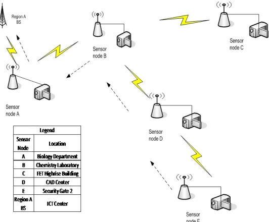
Figure 1: The detailed design of WCSNSS
Each region consists of a BS and camera sensor nodes. A BS consists of wireless radio access point, router, and optional IP camera sensor. The BS must be visible to at least one other BS and one camera sensor node. A camera sensor node refers to any off the shelve IP camera and a wireless access point attached connected together. Camera sensor node can be a fixed or mobile node. A mobile node
is attached to a moving body such as car, bike, bicycle, etc of people resident in any region in the community. The captured data from the mobile node are transmitted whenever there is a visible connection between any other node or the BS as there are onboard storage space on the mobile nodes, hence no need to stream the data in real time.
2.2
Implementation of the design
The detail design of WCSNSS shown in figure 1 was implemented with the selection of various off the shelve camera, wireless access point, router, media server and gateway devices. The power requirement was determined for each sensor node and off the grid solar power source was developed for each node and the BS. The media server and gateway devices were powered from mains electrical supply at region A. InSSIDer network analyzer
ISSN 2348 – 7968
(a) (b) (c)
Figure 2: Result of spectrum analysis: (a) Region A (b) Region B (c) Other regions
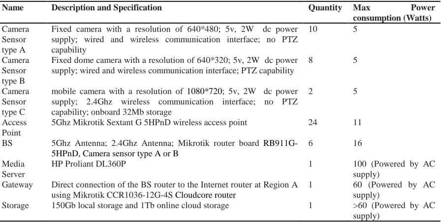
Table 1: Hardware selection and description for WCSNSS
Name Description and Specification Quantity Max Power
consumption (Watts) Camera
Sensor type A
Fixed camera with a resolution of 640*480; 5v, 2W dc power supply; wired and wireless communication interface; no PTZ capability
10 5
Camera Sensor type B
Fixed dome camera with a resolution of 640*320; 5v, 2W dc power supply; wired and wireless communication interface; PTZ capability
8 5
Camera Sensor type C
mobile camera with a resolution of 1080*720; 5v, 2W dc power supply; 2.4Ghz wireless communication interface; no PTZ capability; onboard 32Mb storage
2 5
Access Point
5Ghz Mikrotik Sextant G 5HPnD wireless access point 24 11
BS 5Ghz Antenna; 2.4Ghz Antenna; Mikrotik router board
RB911G-5HPnD, Camera sensor type A or B
6 16
Media Server
HP Proliant DL360P 1 100 (Powered by AC
supply) Gateway Direct connection of the BS router to the Internet router at Region A
using Mikrotik CCR1036-12G-4S Cloudcore router
1 60 (Powered by AC
supply)
Storage 150Gb local storage and 1Tb online cloud storage 1 >60 (Powered by AC
supply)
Table 2: The calculation of the power requirements for the hardware
Camera sensor nodes; BS required a maximum power of 16 Watt of dc power supply as shown in Table 1:
Available battery capacity and voltage (Ah) =18Ah; 12V dc (1)
Maximum power required by these hardware = 16 watts (2)
Battery capacity (Ah) = maximum current drawn (I) x Time (H) (3) Maximum current, I = maximum power required / Battery voltage (4)
Discharge rate = Battery capacity/current (5)
Maximum current I = 16 watts / 12V dc = 1.33 A (6) Discharge rate = 18 AH / 0.833 A = 13.5 Hours (7)
Going by the value of the discharge rate as calculated in Table 2, the camera sensor node will last for 13.5 hours without charging the battery. If the battery is doubled, The node will last for more than 24 hours. To charge the battery by solar radiation requires the determination of
wattage of the solar panel to charge the battery off the grid power supply. The average sunshine hours in Nigeria varies by location from 5 - 8.5 Hours per day [8].
ISSN 2348 – 7968
Table 2a: Calculation of the minimum solar panel wattage required
The minimum solar panel wattage required, SPW is calculated as follows:
SPW = (Battery capacity x solar panel solar panel voltage) / Sunshine hour (8)
For single small battery: 18AH by 12Vdc SPW = (18AH x 12Vdc) / 5 SPW = 43 watts.
Using two batteries with capacity of 18AH by 12Vdc each SPW = (36AH x 12Vdc) / 5
SPW = 86 watts.
Based on the calculations from Tables 2a&b, a 12Vdc, 100 Watts Solar panel, 12Vdc, 10A Solar charge Controller, two of 18AH, 12Vdc Valve regulated Deep cycle Battery and sufficient 1.5mm diameter copper cable were used to setup the off the grid power supply for each camera sensor node and the BS. Voltage splitter was introduced for camera sensor nodes using 5V dc supply.
2.2.1 Software Implementation
The initial functional requirements to be provided by the application software at the following nodes, main BS, BS, camera sensor node are as follows. At the main BS, the software must provide formatting, signal processing and algorithmic analysis of the sensor data; synchronization of data with the cloud platform, initialization and synchronization of all camera sensor nodes. Ensure security and privacy of the data. At the BS and the camera sensor nodes, the software needs to perform basic communication between node to node and node to BS while mobile nodes require additional software functionalities. The mobile node requires a special mobile application that will connect to the user’s smart phone as it can communicate only at 2.4 GHz band. When the user initiates the mobile application, the application connects to the wifi SSID broadcasted from the mobile camera sensor node. The data is transferred, stored on the user’s phone and sent to the BS via the existing BS wifi connections or directly via general packet radio service (GPRS) to the cloud storage depending on the user preference. The mesh network design in Figure 1 was implemented using Mikrotik HWMP+ routing algorithm in [12].
2.2.2 Hardware and software Interconnection The camera sensor nodes and the BS were configured with Hybrid Wireless Mesh Protocol Plus (HWMP+) in proactive mode using Mikrotik RouterOS version 3.1 for setups shown in Figures 3 and 4. Figure 3 was setup so as to ascertain the mesh functionality of the nodes. Figure 4 shows the mesh networking of the six spatially distributed BS over an area approximately 40 Km2. Packets from
camera sensor node E were delivered to BS at region A via three other nodes D, B and A despite no direct association of node E with the BS. Figure 5 shows the BS node and camera sensor node. Mikrotik RouterOS was able to handle all the synchronization and communication among all the nodes in the WCSNSS. Off the shelf software application, SighthoundTM version 2.1 was installed at the
Region A as media server to access and view all the sensor nodes and perform basic object identification and detection. The media server was configured to access Internet and do cloud synchronization and email alert notifications. The mobile application for the mobile nodes was not implemented but the gathered data were uploaded manually using the on-board SD card of each mobile node into the local storage for further processing.
ISSN 2348 – 7968
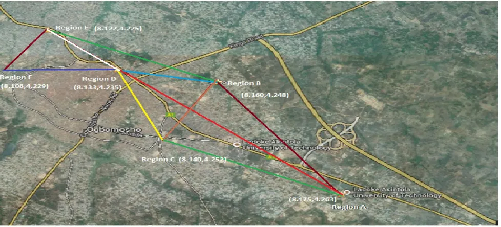
Figure 4: Core Mesh nodes connection for the six regions with the Geo-location coordinates of each BS
-(a)
(b)
(c)
ISSN 2348 – 7968
Figure 5: (a) The BS (b) Mikrotik router board (c) the camera sensor node (d) Mobile camera sensor node
3
Deployment and experimental results
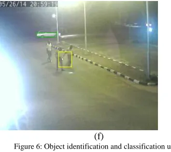
The six BS and eighteen camera sensor nodes were deployed in each of the six regions with solar power sources connected and each nodes was deployed in such a way as to have connection to more than one other nodes. Table 3 shows the actual distance between each of the links described in Figure 4 with the antennas specifications used while Table 4 shows the signal characteristics of the various links in the network. Video data from all the nodes were analyzed for basic object detection and classification as shown in Figure 6(a-f) with coloured rectangle distinguishing different object class such as human, vehicle, motorcycle, etc. The WCSNSS has been up for more than 400 hours since deployment on off the grid solar power source.
Table 3: Links between the core mesh nodes
Link Distance
(Km)
Antenna specification
Region A – Region B 2.0 29dBi Grid - 21dBi panel Region A – Region C 2.3 21dBi panel - 21dBi panel Region A – Region D 6.0 29dBi Grid - 29dBi Grid Region D – Region E 3.5 21dBi panel - 21dBi panel Region E – Region F 2.4 21dBi panel - 21dBi panel
Table 4: Link SNR, RTT and transmission rate
Link SNR (dB)
min, max, avg RTT (ms)
Max. Data rate (Mbps) Region A – Region B 44, 46, 45 0 54 Region A – Region C 44, 46, 45 0 52 Region A – Region D 44, 46, 45 2 52 Region A – Region E 44, 46, 45 2 36 Region D – Region E 39, 43, 41 0 54 Region A – Region F 44, 44, 42 2 39
(a)
(b)
(c)
(d)
ISSN 2348 – 7968
(f)
Figure 6: Object identification and classification using Sighthound
4
Conclusion
We have designed, developed and deployed a low-power, high-quality video capturing test bed platform that can serve as the basis of video-based sensor networks for security surveillance as well as other similar application areas. This work has been able to address the challenge of energy efficiency in sensor networks with the use of low energy equipment and the use of solar power as the major source of energy. WCSNSS has been able to bridge the gap between the physical and logical worlds by reducing human involvement to a barest minimum in community security surveillance system of the selected area. While we have made significant strides in creating a viable video sensor network platform, we are far from done. We are currently in the process of improving the usability, expanding the application scope of the system and experimental evaluation of algorithms, protocols related to wireless camera sensor networks on the platform.
5
Acknowledgments
This work has been supported by the General LAUTECH Senate Research Grant with number LARCU/SRG/13/002 of 2013. The authors would like to thank Ade Adebanjo, James Osunniyi and Tomiwa Odusanya for assistance during configuration, setting up and deployment of the nodes.
References
[1] Akyildiz, I.F.; Melodia, T.; Chowdhury, K.R. (2008): "Wireless Multimedia Sensor Networks: Applications and Testbeds," Proceedings of the IEEE , vol.96, no.10, pp.1588,1605, 2008
[2] Arulogun, O. T, Meine, C. and Emuoyibofarhe, O. J. (2012): “IPv6 Based Wireless Sensor Networks for Electronic Health Monitoring System”, Proceedings of the Fourth International
Conference on Mobile e-Services (ICOMeS), 4:11-17, Oct. 16 – 17, 2012.
[3]Angelakis, V., Genetzakis, M., Kossifidis, N., Mathioudakis, K., Ntelakis, M., Papadakis, S., Petroulakis, N. & Siris, V. A. (2007): Heraklion MESH: an experimental metropolitan multi-radio mesh network.. In P. Steenkiste & B. Raman (eds.), WINTECH (pp. 93-94),: ACM. ISBN: 978-1-59593-738-4
[4] Chen, P., Hong, K., Naikal, N., Sastry, S., Tygar, D., Yan, P., Allen Y.,Y, Chang, L.C, Lin, L., Wang, S., L obatón, E., Oh, S. and Ahammad, P.(2013): A low-bandwidth camera sensor platform with applications in smart camera networks. ACM Transactions on Sensor Networks.
[5]Hughes, D. , Ueyama, J., Mendiondo, E., Matthys, N., Horré, W., Michiels, S., Huygens, C., Joosen, W., Man, K. L. and Guan, S.-U. (2011): “A middleware platform to support river monitoring using wireless sensor networks”, Journal of the Brazilian Computer Society, vol. 17, no 2, pp. 85-102.
[6] Khedo, K. K., Perseedoss, R. and Mungur, A. (2010): “A Wireless Sensor Network Air Pollution Monitoring System”,
Int. J. of Wireless & Mobile Networks, vol. 2, no. 2, pp. 31-45.
[7] Lloret, J., Bosch, I., Sendra, S. and Serrano, A. (2011): “A Wireless Sensor Network for Vineyard Monitoring that Uses Image Processing”, Sensors, vol.11, pp. 6165-6196..
[8] Musa, B.; Zangina, U.; Aminu, M (2012).: Estimation Of Global Solar Radiation In Maiduguri, Nigeria Using Angstrom Model, ARPN Journal of Engineering & Applied Sciences, Vol. 7 Issue 12, p1623 – 1627. Available
at: http://www.arpnjournals.com/jeas/research_papers/rp_201
2/jeas_1212_834.pdf
[9] Romero, R., Muriel, J. L., García, I. and Muñoz de la Peñac, D. (2012): "Research on automatic irrigation control: State of the art and recent results”, Agricultural Water Management, Vol. 114, pp. 59–66.
[10]Song, W., Huang, R., Xu, M., Ma, A., Shirazi, B. and Lahusen, R. (2009): “Air dropped sensor network for real-time high-fidelity volcano monitoring”, In proc. of Mobisys’09.
[11]Tudose, D. S., Voinescu, A. , Petrareanu, M.-T. , Bucur, A. , Loghin, D. , Bostan, A. and Tapus, N. (2011): “Home automation design using 6lowpan wireless sensor networks”, In Proc. of DCOSS, 2011, pp. 1–6.
[12]Yang, L., Chung, S (2012): “HWMP+: An Improved Traffic Load Sheme for Wireless Mesh Networks”, In: HPCC-ICESS: IEEE Computer Society, pp 722-727.
ISSN 2348 – 7968
Arulogun, O. T.is the acting Director of ICT and Senior Lecturer in the Department of Computer Science and Engineering, Ladoke Akintola University of Technology, Ogbomoso, Nigeria. He has published in reputable journals and learned conferences. His research interests include networks security, mobile IPv6, wireless sensor network and its applications. He belongs to the following Professional bodies: Computer Professionals (Registration) Council of Nigeria; Registered Engineer, COREN and International Electrical/Electronic Engineers (IEEE).
Adigun, A. A. has B.Tech, M.Tech and PhD in Computer Science from Ladoke Akintola University of Technology, Ogbomoso, Nigeria where she has been an academic staff member since 1998. Her research interests are Data Mining and Data Engineering. Dr. Adigun is a member of Computer Professionals of Nigeria (CPN) and the National Computer Society (NCS). Dr. Adigun is currently a visiting lecturer at Landmark University, Nigeria.
Okediran O. O. has B. Tech., M. Tech. and PhD degrees in Computer Engineering from Ladoke Akintola University of Technology, Ogbomoso, Nigeria. His research interests include: application of computational techniques to network security, modeling and simulation of complex systems interactions. He belongs to the following professional bodies: Full member, Computer Professionals (Registration) Council of Nigeria (MCPN); Registered Engineer, Council for the Regulation of Engineering in Nigeria (COREN).