Single point incremental sheet forming investigated by
in-process 3D digital image correlation
N. Decultot1,2, L. Robert1,2,a, V. Velay1,2, and G. Bernhart1,2
1 Universit´e de Toulouse; INSA, UPS, Mines Albi, ISAE ; ICA (Institut Cl´ement Ader); Campus
Jarlard, F-81013 Albi, France
2 Ecole des Mines Albi, Campus Jarlard, F-81013 Albi, France
Abstract. Single Point Incremental Forming (SPIF) is a promising sheet metal forming process for prototyping and small batches, in which the blank is formed in a stepwise fash-ion by a displacement-controlled small-sized tool. Due to specific strain paths induced by the process and limited plastic zones in the contact region between the tool and the work-piece, forming diagrams and forming strategies are different from the classical stamping processes. One major limitation of SPIF is the lack of accuracy of the obtained final parts because of the poor knowledge of the state of stress during the process that requires a good description of the material models and a right choice of the process parameters. In this paper, the SPIF process is experimentally investigated by the mean of surface 3D digital image correlation during the forming of a AW-5086-H111 grade aluminium alloy. Development of strain fields encountered in incremental forming is reported and material formability is evaluated on several formed shapes, taking into account a wide range of straining conditions of this process.
1 Introduction
Single Point Incremental Forming (SPIF) is a sheet forming process that has gained interest recently in prototyping and small batch production. In this process, a sheet metal part (aluminium, steel) is formed in a stepwise fashion by a displacement-controlled hemispherical tool without the need for a supporting die [1]. This process enables the manufacturing of a desired shape by an incremental deformation in a small contacted region. Because of this slicing technique, complicated products can be fabricated by using a simple shaped punch driven by a numerically controlled milling machine or a robot with a non-dedicated die. As a result this process is characterised by a high flexibility which allows an interesting technology improvement to manufacture sheet metal parts in comparison with drawing process, and a reducing costs when prototypes or small batches have to be manufactured. Due to specific strain paths induced by the process and the fact that the plastic zone is strictly limited to the contact region between the tool and the work-piece, forming-limit curves and forming strategies are different from the classical deep drawing process [2]. The formability is generally characterized by the draw angleΦ(or wall angleα), defined by the sine lawtf = t0sin(π/2−Φ)= t0sinαwhere t0andtf are the initial and final thicknesses of the part, respectively. The largest design draw angle Φin the part must be less than Φmax which can be considered as a material parameter limit [1]. It is reported however that accuracy of the obtained shape due to springback effect [4], heterogeneous thickness strain distribution [3] and fabrication time are limitations of the process. Furthermore, sim-ulations by Finite Element methods are time-consuming because of the incremental characteristics of the process [1]. However, these simulations need a good description of the process parameters, of the boundary conditions and of the material properties by the use of behaviour model representative of the
a e-mail:[email protected] © Owned by the authors, published by EDP Sciences, 2010 DOI:10.1051/epjconf/20100611001
incremental characteristics of the process, taking into account, for instance, the history of strain paths during the process. For studying these issues, a SPIF process pilot has been developed in the labora-tory and instrumented with a force sensor to measure the resultant loading applied to the sheet metal part during the forming and with a multi-camera system to measure the shape variation of the sheet metal part and the 3D displacement/strain field of its surface by 3D-Digital Image Correlation (3D-DIC) techniques. Quite recently, Vasilakos et al. [5] have also used the 3D-DIC technique to study the deformation phenomena of a two-angle pyramid sheet metal part during SPIF operation. They mea-sured the out-of-plane displacement of only six points selected on the sheet metal and analysed the deviation (maximum displacement minus final displacement) during the forming. They concluded that the spring-back effect occurs immediately after the tool transit over the investigated material point and is only responsible for a minor fraction of the total geometrical error. However, they did not analysed directly strain fields.
The main objectives of this paper were to investigate, thanks to the high strain resolution and spatial resolution of the 3D-DIC technique, (i) the development of the strain fields encountered in incremental forming and (ii) the material formability in incremental forming, taking into account the wide range of straining conditions of the SPIF process. Therefore, different tests were designed: from a simple uni-axial tool path displacement over the blank with incremental penetration of the punch (Z-mouvement between successive loops), to crosses and pyramids, in order to cover a set of straining conditions ranging from uniaxial, pure uniaxial stretching, to fully biaxial stretching. In that conditions, some of the main SPIF parameters, typically the vertical increment step size∆zand the tool diameterDpwere investigated. Finally, forming diagrams were assessed.
In section 2, the design of the SPIF process pilot is first presented. Principle of the 3D-DIC is then recalled and chosen parameters are justified. In section 3, results of 3D-DIC full field measurements in term of strain fields, strain paths and forming diagrams for different tests are presented and discussed.
2 Experimental equipment and method
2.1 The SPIF Process Pilot
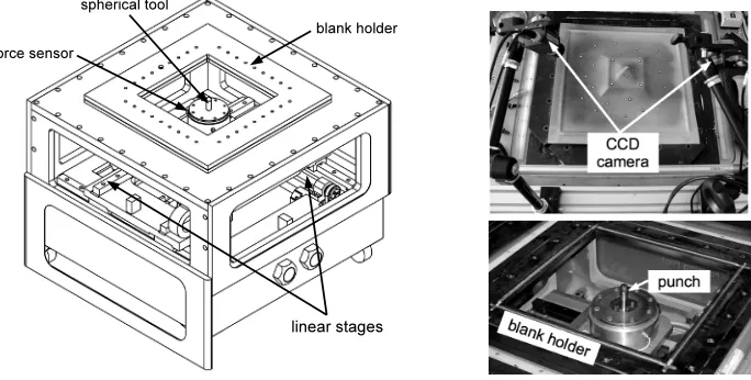
A SPIF process pilot has been developed in order to reproduce complex loading paths close to those induced in an industrial environment. It consists of a parallelepiped frame body. A properly designed blank holder was utilised to clamp the 500×500 mm2 square blank on its top (see Figure 1). Below,
Fig. 1.The SPIF process pilot. CAD of the pilot (left), top view details (right).
screw spindles. It allows on the one hand a vertical (Z) tool displacement and a local stamping of the sheet and, on the other hand, a horizontal tool displacement in the frame of the sheet (X,Y) leading to the incremental forming of the piece. The tool path was specified by the pilot control with a computer connected to the later through a proper routine. The sheet deformation was performed with a 10 or 20 mm diameter hemispherical punch made of X38CrMoV5 tool steel. A 400×400 mm2work area can be studied in the current configuration of the machine and a 100 mm depth of draw can be reached. In order to form the piece, a bottom-top forming direction was considered. As a consequence, its design allows us the easy use of CCD cameras to perform in situ measurement of the deformation of the sheet by 3D-DIC (see section 2.2). Furthermore, a multi-axial sensor sets up the pilot that enables to monitor the three dimensional force measurement induced in the sheet by the punch displacement. The friction coefficient can be evaluated from this force measurement. For all the experiments, an EN AW-5086-H111 grade of aluminium alloy sheet of 1 mm thick was considered. A film of fluid grease was applied to the blank to reduce friction.
2.2 3D-Digital Image Correlation (3D-DIC)
The 3D-DIC method is based on both digital image correlation (DIC) and computer stereo vision (utilisation of two cameras), and was developed at the end of the last century [6]. This technique uses a DIC algorithm to determine point correspondences between two images of an object to be measured, acquired from two different view points, by two rigidly bounded cameras. The correlation scores are computed by measuring the similarity of a fixed subset window in the first (left) image to a shifting subset window in the second (right) one. A first order subset shape function and a zero normalized sum of square difference (ZNSSD) correlation criterion are used. Sub-pixel correlation is performed using B-spline gray level interpolation. After determining the calibration parameters for each camera as well as the 3-D relative position/orientation of the two cameras (pinhole model and radial distortion of 1rd order), the 3-D shape of the object can be reconstructed by triangulation from the image-points correspondences founded by DIC. To determine the 3-D displacement field, DIC is also used to determine image-points correspondences between the stereo pairs acquired before and after deformation (temporal tracking) [7]. The Hencky logarithmic surface strain field tensor is obtained from the displacement field by numerical differentiation. A complete description of the 3D-DIC technique can be found in [8].
The stereo rig was composed of two 8 bit AVT Marlin F-145B2 CCD cameras allowing a 1392×1040 pixels resolution equipped with 25 mm lenses. Two synchronized images were taken at the frequency of 2 Hz. The calibration and numerical image processing were carried out with the assistance of the Vic-3D commercial software [9]. As the DIC technique relies on a contrasting pattern on the surface of the test object, a randomly distributed white paint pattern was applied on the painted in black side of the sheet metal. A particular attention was paid to have a relatively fine speckle pattern size propor-tional to the region of interest, leading to a choice of a maximum 15×15 pixels2subset size (minimum 11×11 pixels2). This allowed to increase the displacement spatial resolution in mm (subset size × magnification factor) because large strain gradients were present. Typical magnification factor of 8 px/mm gave a 2×2 mm2 displacement spatial resolution. The strain spatial resolution (optical gauge size) was also minimised and chosen equal to 2×2 mm2. It has been shown in another study [10] that strain standard uncertainty can be estimated to 10−4in similar experimental conditions.
3 Results and discussion
3.1 Analyses of a simple uniaxial tool path
observed. In order to have an area where almost pure biaxial stretching conditions must be achieved, a cross consisting of two perpendicular straight lines was finally formed [11]. A series of 171 pairs of images (171 steps) have been automatically taken before the ductile fracture occurs.
Figure 2(a) presents the 3D shape of the stamped cross measured by 3D-DIC for the step]140. Figure 2(b) reports the major strain field superimposed on the black and white painted speckle patterns
(a) (b)
Fig. 2.(a) Shape of the formed part. (b) Maximum principal strain field and definitions of the lineLand areasA
toE. (Both at the step]140 of 171 stamping steps before fracture.)
of the blank, also for the step]140 which corresponds to a maximum major strain of about 35%. It appeared that major strain was not constant along the straight lineLand maximum values were situated near areaC(see Figure 2 for the definition of the line). An analysis of the straining evolution along lineLfor several steps of the forming is presented in Figure 3 for both major and minor strains.
(a) (b)
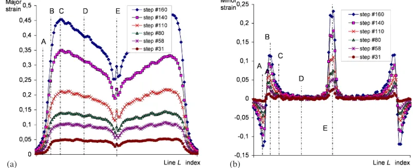
Fig. 3.Strain evolutions along lineLfunction of the depth of forming (see Figure 2 for the definition of lineLand areas). Left: major strain, right: minor strain. Only six image steps are presented, from step]31 to step]160.
It was also observed that there was a large decrease of the major strain between C and Efor almost no minor strain whereas the tool trajectory was a horizontal straight line. Moreover out-of-plane displacement W (which is quite equal to the Z value as the initial blank shape is flat) showed the inverse tendance: W increases continuously from areasAtoE, as shown in Figure 2, due to the other punch trajectory perpendicular to the later. This is more visible as the depth of punch penetration increases (steps]110,]140 and]160). As a probable consequence, the ductile tearing occurred near the areaC.
3.2 Influence of increment step size and punch diameter
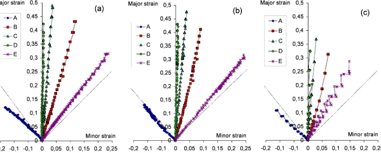
The cross presented in Figure 2 have been formed considering two punch diametersDp =10 and 20 mm and two increment step sizes∆z = 0.5 and 2 mm. Figure 4 shows strain paths of the five areas A,B,C,DandEdefined before on forming diagrams plots (major versus minor strain). Whatever
Fig. 4. Strain paths of the five areas (A,B,C,Dand Eon the stamped part, see Figure 2(b)) for two punch diametersDpand two increment step sizes∆z: (a)Dp=10 mm,∆z=0.5 mm; (b)Dp =20 mm,∆z=0.5 mm;
(c)Dp=20 mm,∆z=2 mm.
the punch diameter or increment step size, forming diagrams are very similar. Pure biaxial stretching is never totally reached (areas E), and the effect of the punch diameter (Figures 4(a) and 4(b)) is less significant than the effect of the increment step size (Figures 4(b) and4(c)). As reported before, the ductile tearing occurred near the areaC, permitting to detect the critical strain for quasi uniaxial stretching conditions. In the literature, most authors generally reported the maximum major strain at tearing for no minor strain in the Forming Limit Diagram (FLD), notedFLD0 [1]. It is worth pointing out that hypothesis leading to FLD are not available in the case of SPIF, because through-thickness stresses are not negligible in that case of a small tool diameter. In our experiments, however, maximum major strain values before tearing (obtained between areasCandD) were equal to 55%, 51% and 45% for respectively the following conditions [Dp=10/∆z=0.5], [Dp=20/∆z=0.5] and [Dp=20/∆z=2] (in mm). Values are slightly higher than those reported in Figure 4 because they are not exactly extracted at the physical pointCorD. Note also that in each case, minor strain do not exceed 4%. To conclude, it is reported that sheet formability decreases with increasing increment step size and tool size [1], but fracture does not occur at the centre of the cross (biaxial stretching conditions) as reported in [11], but for almost uniaxial stretching conditions.
3.3 Analyses of complex tool paths
rounding at the corners, except those due to the punch diameter (see Figure 5). The tool paths were square loops, each loop consisting of four straight lines. Dimensions of the first loop were 100×100 mm2. The depth increment step size was equal to∆z=2 mm and the in-plane increment step size was equal to∆x=∆y=2 mm, as for a theoretical draw angleΦof 45◦, and the complete part was obtained after 25 loops. The tool diameter wasDp=20 mm.
(a) (b)
Fig. 5.Stamped small pyramid without rounding, shape measured by 3D-DIC for the last strain step. (a) Major strain field superimposed on the 3D shape. (b) Minor strain field and definition of lines 1 and 2 (planar view).
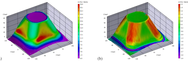
The second part was a large truncated pyramid shell with rounding at the corners (see Figure 6). The tool paths were square loops with rounding at the corners. The rounding radius was kept constant and equal to 50 mm while the dimensions of the first loop are 240×240 mm2. The depth increment step size was varying for the first five loops respectively as∆z={10; 8; 6; 4; 2}mm and then was kept constant and equal to∆z=2 mm. The in-plane increment step size∆x=∆ywas always equal to∆z, as for a theoretical draw angleΦof 45◦. The complete part was obtained after 25 loops so that the height of the formed part was 10+8+6+4+2×21=70 mm, implying that the last tool path was exactly a circle of 50 mm diameter as it can be seen on the top of the truncated pyramid in Figure 6.
(a) (b)
Fig. 6.Stamped large truncated pyramid with rounding at the corners, shape measured by 3D-DIC for the last strain step. (a) Major strain field superimposed on the 3D shape. (b) Minor strain field.
and part size, this effect is widely reduced for the large truncated pyramid but can also be observed in Figure 6.
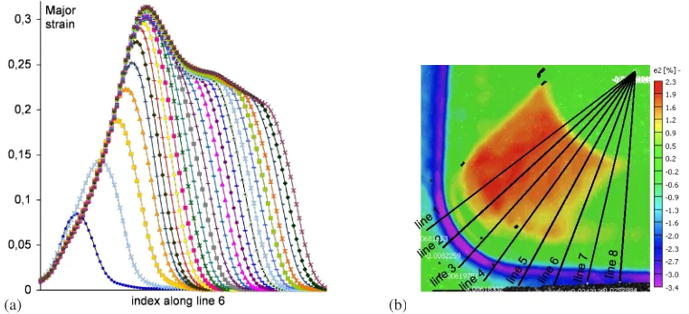
On the other hand, it is also possible to analyse the evolution of the strain amplitude during the incremental forming of the pyramid. Figure 7(a) presents the major strain along line 6 (defined in Figure 7(b)) for all the 25 incremental forming loops of the truncated pyramid. As expected, the first
(a) (b)
Fig. 7.Large truncated pyramid. (a) Evolution of the major strain along line 6 for each of the 25 incremental loops. (b) Definition of the lines in the quarter of the pyramid (minor strain map).
five loops for which∆zwas respectively equal to 10; 8; 6; 4 and 2 mm gave the larger strain increment amplitude, respectively 8.43; 5.81; 4.46; 3.56 and 2.9%. The variation between the increment step size and the strain increment is non linear, probably due to structural and spring-back effects. After about the tenth loop, surprisingly, the major strain increment amplitude highly decreases whereas the punch continues to formed with a constant depth increment step size of 2 mm. As a consequence, the major strain decreases globally along line 6 from 31% to 21%, leading to the heterogeneous major strain field alongZon the flat faces observed in Figure 6(a). This trend was not observed for the small pyramid.
Finally, from the strain fields measured by 3D-DIC, the forming diagrams for both pyramid stamped parts can be plotted (see Figure 8). As a first remark, large biaxial stretching was obtained for the small pyramid because there was no rounding at the corners. Indeed, if the corner radius is simply equal to the one of the hemispherical head of the punch, nearly biaxial stretching conditions are achieved in the material. Consequently, uniaxial strain field was almost homogeneous excepted along the corners. This is illustrated by the analysis of the strain along two specific lines: line 1 (maximum major strain area) and line 2 (maximum minor strain area), superimposed on the forming diagram of Figure 8(a), for several image steps. As expected we observe that the blank undergoes a nearly pure biaxial stretch-ing along line 2 (maximum 17% of minor strain is achieved for 20% of major strain) and a nearly pure uniaxial stretching along line 1.
(a) (b)
Fig. 8.Forming diagrams for both pyramid-like stamped parts. (a) Small pyramid without rounding. In bold symbols are represented the strain paths along lines 1 and 2 defined in Figure 5(b) for several image steps from step
]49 to last step]123. (b) Large truncated pyramid with 50 mm radius roundings. In bold symbols are represented the strain paths along the 8 lines defined in Figure 7(a) for the last forming step.
4 Conclusion
We have investigated in detail, thanks to the high strain resolution and spatial resolution of the 3D-DIC technique, the development of strain fields encountered in incremental forming of a AW-5086-H111 grade of aluminium alloy. The material formability in incremental forming have been evaluated, taking into account the large range of straining conditions of this process. The analysis of the formed cross has shown that fracture occurs in the uniaxial stretching domain, andFLD0have been set to 55% for this material. It is also experimentally reported that sheet formability decreases with increasing increment step size and tool size. Pyramid experiments have shown that straight line punch displacement involves pure uniaxial stretching. When the punch displacement is curvilinear, a small level of minor strain for a given major strain can be measured that becomes very important for a bending radius which tends toward the radius of the hemispherical tool (pure biaxial stretching conditions).
References
1. Jeswiet, J., Micari, F., Hirt, G., Bramley, A., Duflou, J., Allwood, J., CIRP Annals54, (2005) 623 2. Jeswiet J., Young D., Proc. IMechE Part B: J. Eng. Manufacture219, (2005) 359
3. Kim, T. J. and Yang, D. Y., Int. J. Mech. Sci.42, (2000) 1271
4. Micari F., Ambrogio G., and Filice L. , J. Mat. Proc. Tech.191, (2007) 390
5. Vasilakos I., Gu J., Belkassem B., Sol H., Verbert J., and Duflou J. R., Key Eng. Mat., 410-411(2009) 401
6. J. Helm, S. McNeill and M. Sutton, Opt. Eng.35, (1996) 1911 7. D. Garcia, J.J. Orteu, L. Penazzi, J. Mat. Proc. Tech.125, (2002) 736
8. M. A. Sutton, J.-J. Orteu and H. Schreier,Image Correlation for Deformation and Shape Measure-ments: basic concepts, theory and applications (Springer, 2009) 364p.
9. Vic-3D software, Correlated Solutions Inc., (2010) http://www.correlatedsolutions.com/ 10. L. Robert, F. Nazaret, T. Cutard and J.-J. Orteu, Exp. Mech.47, (2007) 761