Fused Floating Point Three Term Adder Using Brent-Kung
Adder
Ms. Neena Aniee JohnP
1
P
and Ms. Binu ManoharP
2
P
1
P
Electronics and communication Mangalam college of EngineeringKerala,
India,31TU[email protected]U31T
P
2
P
Electronics and communication Mangalam college of EngineeringKerala,
India, 31TU[email protected]U31T
ABSTRACT
A fused floating-point three-term adder which performs two additions in a single unit to achieve better performance and accuracy compared to a network of discrete design. To further improve the performance of the three-term adder, several optimization techniques are applied. This include a new exponent compare and significand alignment, dual-reduction, early normalization, three-input leading zero anticipation, compound addition/rounding and pipelining. The fused floating-point three-term adder reduces the area and power consumption compared to a discrete floating-point three-term adder. Brent- Kung is a parallel prefix form of the carry look ahead adder. It takes less area compared to other parallel prefix adder.
1. INTRODUCTION
The Floating-point operations require complex processes such as alignment, normalization and rounding, which increases the area, power consumption and latency. Therefore to further reduce the overhead, fused floating-point units have been proposed, which performs several operations in a single unit. Several algorithms and optimization techniques are applied to improve the performance of fused floating point adder.
1) Proposed a new exponent compare and significand alignment. Here the three exponent differences are computed in parallel and the differences are used for the significand alignment. The largest exponent and three aligned significands are determined by the control logic. This approach reduces the latency by performing the exponent processing and significand alignment simultaneously.
2) To check significand addition is positive or negative, dual reduction is used. Two reduction trees generated both the positive and negative significand pairs and the positive significand pair is selected based on the significand comparison.As the selected significand pair produces a positive sum the complementation after the significand addition is avoided, so that the latency is reduced.
3) To reduce the significand addition early normalization is applied. The adder size can be reduced by performing the normalization earlier and the rest of bits are used for rounding, which significantly reduces the latency.
4) As the normalization is performed prior to the significand addition, the Leading Zero Anticipation (LZA) and normalization shift has been done.To re- duce the latency, a three-input LZA is used.
5) For fast rounding Compound addition is used. The compound addition gives the rounded and unrounded sums together. The round logic is used to select the correct one .
2. FUSED FLOATING-POINT THREE-TERM ADDER
The traditional fused floating-point three-term adder is an initial design so that optimizations can be applied to improve the performance. Fig. 1 shows the modified design for fused floating-point three-term adder. Here five optimizations for the fused floating-point three-term adder are described: 1) A new exponent compare and significand alignment scheme, 2) Dual-reduction to avoid the need for complementation after the significand addition, 3) Early normalization, 4) Three-input LZA, and 5) Compound addition and rounding.
Fig.1. A fused floating-point three-term adder
2.1 Exponent Compare and Significand Alignment
The three operands determine the largest exponent and aligned significands. Based on exponent difference the largest exponent is determined. The significand alignment is determined based on exponent differences. This approach requires performing the exponent subtractions, complementation and significand shift sequentially, which takes a large latency. In order to reduce the latency, a new exponent compare and significand alignment logic is proposed as shown in Fig.2. Six subtractions are performed to compute all the combinations of (expRaR-expRbR, expRbR-expRa R,expRbR-expRcR, expRcR -expRbR, expRcR-expRaR and expRaR-expRcR) differences, an absolute value is selected based on the exponent comparison result, which enables skipping the complementation after the subtractions.
Fig.2. Exponent compare and significand alignment logic
The exponent differences are used for the significand shifters.The sticky logic is performed inorder to determine the guard, round and sticky bits. The first and second bits of the LSB are the guard and round bits. If one of the over shifted bit is 1,then the sticky bit is set to 1.The sticky bit can be implemented with OR trees. The remaining over shifted bit is discarded.Fig. 3 shows the significand shifter and sticky logic example for the single precision.
Fig .3. Significand shifter and sticky logic for the single precision
Based on the exponent comparison results which is shown in Table I,the control logic determines the largest exponent and the aligned significands.
Table I: Exponent Compare Control Logic
The aligned significands become 2f + 6 bits wide including two overflow bits, and guard, round and sticky bits, where f is the number of the significand bits as shown in fig 4.
Fig.4.Significand process—alignment, invert, reduction, normalization, addition and rounding
2.2. Invert & Dual-Reduction
The sign logic generates the three effective sign bits ( sign_eff_a,sign_eff_b and sign_eff_c) based on the three sign bits and two op codes as
Sign_eff_a =sign_a
Sign_eff_b =sign_a ⊕ (sign_b ⊕ op1) Sign_eff_c=sign_a ⊕ (sign_c⊕ op2
...(2)
Where op1 and op2 are the first and second op codes, respectively. Based on the effective sign bits the aligned significands are inverted. 2 bits are extended to the LSB of the significands to avoid the increments after the inverters,. Table II shows the 2 bit extended LSBs based on the effective sign bits.
Table II: 2 Bit Extended Lsbs For Complementation
Inorder to eliminate the complementation after the significand addition dual-reduction is used. One reduction tree takes the three inverted significands and the other takes the reversely inverted significands. (e.g.A-B-C and –A+B+C). The two 3:2 CSAs produce the two reduced significand pairs. Based on the sign of the significand sum,the positive pair is selected .
For the delay-optimization, the first part of the significand addition is performed after the reduction .The addition performs a PG generator. A Kogge-Stone adder is used to perform this addition . The level 0 (for pi and gi) and level 1 are implemented here.
Pi=ai ⊕ bi Gi=aibi
P ij=pi pi-1….pi +(2j-1)
Gij=gi + gi-1 pi+….+gi - (2j - 1)pi pi-1….pi - (2j- 2) ……….(3)
Where ai and bi are ith bits of the two significands and j is the level of the prefix tree adder.
2.3. Early Normalization
The aligned significand of traditional fused floating-point three-term adder is 2f+ 6 bits, where f is the number of significand bits. Such large significands require a large significand addition and normalization.To reduce the overhead, early normalization is applied. As shown in Fig.4, the normalization is performed prior to the significand addition. Therefore the significand adder size
is reduced to f+1 bits and the rest of lower bits (f+7) are passed to rounding.
2.4. Three-Input LZA and Significand Comparison
The three-input LZA encodes the three inputs at once.The three-input LZA consists of two parts: 1) Pre-encoding indicator vectors and 2) Leading Zero Detection (LZD) logic for generating the leading zero count. The pre-encoder performs the bitwise operations to generate the W vector as
W=A+B+C
wi=ai+bi+ci, wi €{0,1,2,3} ……….…. (4)
where ai,bi,ci are the ith bits of the three significands. The W vector can be represented by one of the four elements, pRiRP
0
P
, pRiRP
1
P
, pRiRP
2
P
and pRiRP
3
P
, indicating wi equals to 0, 1, 2 and 3, respectively.
pRiRP
0
P
=1 if wi =0 pRiRP
1
P
=1 if wi=1 pRiRP
2
P
=1 if wi=2 pRiRP
3
P
= 1 if wi=3.
Using the four elements, the W vector is pre-encoded into three symbols, zi,ti and gi as
zRiR= pRiRP
0
P
(pP
0
PRi-1R+pP
1
PR
i-1R)+pRiRP
3
P
(pP
2
PRi-1R +pP
3
PRi-1R) tRiR= (pRiRP
0
P
+ pRiRP
2
P
)( pP
2
PRi-1R +pP
3
PRi-1R)+( pRiRP
1
P
+ pRiRP
3
P
)( pP
0
PRi-1R+pP
1
PRi-1R) gRiR= pRiRP
1
P
(pP
2
PRi-1R +pP
3
PRi-1R)+ pRiRP
2
P
( pP
0
PRi-1R+pP
1
PRi-1R) ……….. (5)
The F vector is computed with the three symbols as
fi = ti+1(giZ�i−1+ Zig�i−1) + t̅i+1(ZiZ�i−1+ gig�i−1) ……….(6)
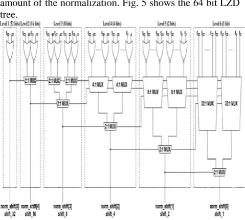
The F vector is passed to the LZD logic. The LZD produces the leading zero count which becomes the shift amount of the normalization. Fig. 5 shows the 64 bit LZD tree.
Fig 5. 64 bit LZD tree for the single precision.
2.5. Compound Addition and Rounding
The normalized significand pair is passed to the significand addition and rounding. The upper significand bits are used for the addition and the lower bits are used for rounding .The significand addition result needs to be right shifted for the post-normalization. Fig.6 shows the significand result selection and the rounding position depending on the overflows of the significand addition. OR2 Rand OR1R represent two overflow bits; LR2R ,LR1Rand LR0Rare the LSBs if there is two, one or no overflow; G, R and S mean the guard, round and sticky bits, respectively. Since the significand sum produces the overflow of at most 2, the two overflow bits OR1R and OR2R are mutually exclusive.
Fig.6. Significand result selection and rounding position.
The compound addition and rounding for the fused floating-point three-term adder is shown in Fig. 7. The compound addition determines the upper f bits including two overflow bits, and the rounding determines the rest of three LSBs and the round decision. The upper f + 1 are passed to the compound addition. Based on the overflow bits two significand sums are right shifted by 2. Based on the round decision .the correct significand sum is selected.
Fig. 7. Compound addition and rounding.
To determine if the significand sum is rounded up or not the round logic requires computing the LSB, carry, guard, round and sticky bits (L, C, G, R and S). As described in Fig.6, the rounding position varies depending on the overflow. Therefore, three rounding cases (i.e., two, one, and no overflows) are separately computed. Fig.8 shows the round logic.
Fig.8 .Round logic.
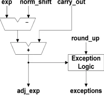
The largest exponent is adjusted by subtracting the shift amount from the LZA and adding the carry-out of the significand addition as shown in Fig. 9.
Fig. 9.Exponent adjust logic
Using the adjusted exponent, the exceptions are detected. The three exception cases are
Over flow = 1 if exp ≥ max _exp 0 otherwise
Under flow = 1 if exp ≤ 0 0 otherwise
Inexact = round _ up\ overflow \ under flow. Where round _ up is the rounding decision of the
significand addition result.
3. MODIFICATION
3.1 Kogge-Stone adder
Kogge-Stone adder is a parallel prefix form carry look ahead adder. Kogge-Stone prefix adder is a fast adder design. KS adder has best performance in VLSI implementations. It shows the less delay among other architectures so Kogge Stone adder is used for wide adders. In fig 10 each vertical stage produce Propagate and Generate bits. Generate bits that produced in the last stage are XORed with the initial propagate after the input to produce the sum bits. The 2-bit Kogge- Stone adder is shown below.
Figure 10: 2-bit KS Adder
But the major drawback of Kogge-Stone adder is it has large area. So we replace Kogge-Stone adder with Brent-Kung adder.
3.2 Brent Kung Adder
Brent- Kung is a parallel prefix form of the carry look ahead adder. It takes less area to implement than the other prefix adders such as Kogge- Stone adder and it also has less wiring congestion. Instead of using a carry chain to calculate the output, the method shown in Figure 11 is used.
Figure 11: 4-bit BK Adder
This will reduce the delay without compromising the power performance of the adder. Replacing the Kogge-Stone adder with the above structure of Brent-Kung adder in the part of addition we can see that there is significant reduction in area, power and delay.
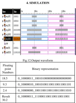
4. SIMULATION
Fig.12.Output waveform
Floating point Numbers
Binary representation
18.5 0_10000011_100101000000000000000000
9.3 0_10000010_100101001100110011001101
2.4 0_10000000_100110011001100110011010
Result 30.2
0_10000011_11100011001100110011001
Table 3: Tabulation of output 4.1 Tabulation Results
COMPARISON OF POWER DELAY PRODUCT
Using Kogge –Stone adder Using Brent-Kung adder
Power =520 Power = 133
Delay = 78.332 Delay = 72.835
Power delay product=40732.64
Power delay product=9687.055
Table 4: Comparison of power delay product
COMPARISON OF AREA DELAY PRODUCT
Using Kogge –Stone adder Using Brent-Kung adder
Area =1357 Area = 1024
Delay = 78.332 Delay = 72.835
Area delay product=106296.524
Area delay product=74583.04
Table 5: Comparison of area delay product
5. CONCLUSION
The fused floating point three term adderweredemonstrated. The adder were implemetated in VHDL.The main advantages of the implementation using Brent-Kung is that it reduces area,power and delay compared to that of Kogge-Stone adder. Several algorithms and optimization techniques are applied: 1) A new exponent compare and significand alignment 2) Dual-reduction, 3) Early normalization, 4) Three-input LZA and 5) Compound addition and rounding.
6. REFERENCES
[1] Jongwook Sohn and E. E. Swartzlander, Jr., “A fused floating-point three-term adder,” IEEE Trans. Circuits Syst., 2014 ,pp. 2842–2850.
[2] Y. Tao, G. Deyuan, F. Xiaoya, and R. Xianglong, “Three-operand floating-point adder,” in Pro. 12th IEEE Int. Conf. Comput. Inf. Technol., 2012, pp. 192– 196.
[3] H. H. Saleh and E. E. Swartzlander, Jr., “A floating-point fused dot- product unit,” in Proc. IEEE Int. Conf. Computer Des., 2008, pp.427–431.
[4] H. H. Saleh and E. E. Swartzlander, Jr., “A floating-point fused add- subtract unit,” in Proc. 51st IEEE Midwest Symp. Circuits Syst., 2008 ,pp. 519–522.
[5] T.Lang and J. D. Bruguera, “Floating point fused multiply add with reduced latency,” IEEE Trans. Computers, vol. 53, pp. 988–1003, 2004.